Table of Contents
Advertisement
Quick Links
Advertisement
Table of Contents

Subscribe to Our Youtube Channel
Related Manuals for Carf-Models DG 800 S


Summary of Contents for Carf-Models DG 800 S
-
Page 1: Instruction Manual
DG 800 S Instruction Manual F.W. 28/7/2014 Vers.1.0... -
Page 2: Liability Exclusion And Damages
However, as manufacturers, we at CARF-Models are not in a position to influence the way you build and operate your model, and we have no control over the methods you use to install, operate and maintain the radio control system components. - Page 3 Important/General Notes Elastic Hinges: The ailerons, flaps and elevator are all hinged already for you - laminated in the mould and attached with a special nylon hinge-cloth, sandwiched between the outer skin and the foam. This nylon hinge is 100% safe and durable. You will never have to worry about breaking it, or wearing it out.
- Page 4 Take Care: Composite sandwich parts are extremely strong, but fragile at the same time. Always keep in mind that these composite airplanes are designed for minimum weight and maximum strength in flight. Please take care of it, especially during transport, to make sure that none of the critical parts and linkages are damaged. Always handle your airplane with great care, especially on the ground and during transport, so you will have many hours of pleasure with it.
- Page 5 This does not damage the paint, as Acetone and many other solvents will, and this is what we use at the factory. At CARF-Models we try our best to offer you a high quality kit, with outstanding value-for-money, and as complete as possible. However, if you feel that some additional or different hardware should be included, please feel free to let us know.
-
Page 6: General Information
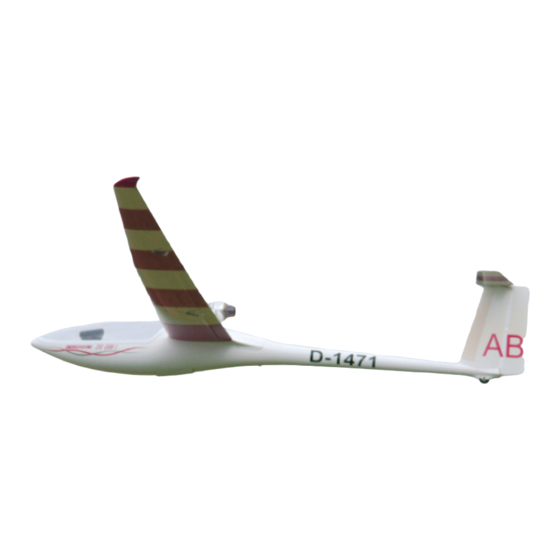
General information The wing of your CARF-Models DG-800S is a so called all carbon wing. The skin has several layers of carbon fibre as well as the C-spars. These are laminated in separate molds, all carbon, of course. The fuselage is made from various glass... - Page 7 Liste Der Enthaltenen Bauteile Material Name Piece For What Threaded end M3 with hold for steel cable Ruder PULL PULL WIRE DIA 0.8MM 2 x 2 Meter Ruder CRIMP TUBES DIA 2MM Ruder Clevis M3 Ruder ALLEN SCREW M 3*12 Ruder WASHER M3 Ruder...
- Page 8 milled wood parts and hardware Rudder servo tray Retract mounts Retract Servo tray milled parts for RC equipment Cockpit tub and parts Milled instrument panel...
- Page 9 Milled wood parts and hardware Horizotal Stab Rudder Retract Wing Tow release 20mm (standard size) 16 mm (mini size) servo servo mount parts mount parts...
- Page 10 Horizonal stab installation Install a standard size high quality elevator servo with the included 2.9 x 13 mm self tapping screws. Use washers if necessary. The elevator linkage is assembled from the 20 mm M3 all thread and 2 spring steel clevises. NOTE: Since space is very tight, these clevises must be secured with LOCTITE after the final elevator setting is adjusted.
-
Page 11: Horizontal Stab Installation
Horizontal stab installation Extend the servo wire, either by soldering an extension or connecting a pigtail socket. Secure the extension so that it cannot disconnect under any circumstances. It is helpful to use the tailwheel opening to feed the wire forward. Use cable sockets to secure it to the fuselage wall. - Page 12 RECENT UPDATE! Note: During countless test flights it has been noticed that the stab incidence should be reduced by 0.7 degree in order to maximize the performance of our DG-800. Even though the plane is flying very well with the incidence out of the box in slower thermal flying, the faster you want to fly, the more you feel you need to trim down elevator.
-
Page 13: Rudder Servo Installation
Rudder servo installation The rudder servo tray is already assembled and holes for the servo are drilled. Use 2.9 x 13 mm self tapping screws and washers to install your standard size servo (preferrably of the same type as the elevator servo) Then bolt the servo tray from the rear against the landing gear former. -
Page 14: Rudder Installation
Rudder installation The spar with the hinge posts is already installed and glued securely. Also the rudder has the hinge pin sleeves and the cut- outs preinstalled. It can be attached to the fin immediately. Attach the steel wires by looping them through the control horns and crimp them with the included crimp sleeves. - Page 15 Rudder installation Trial fit the hinge pin, either conventionally from the top (where you can always see it) or from the bottom, like shown in the photo. In that case it is important to secure the pin against accidental loss. Bend the end approx. 10-12 mm (1/2”)
-
Page 16: Tail Wheel Installation
Tail Wheel Installation The tail wheel axle can be made from either M3 or M4 bolt, 35 mm long, depending on the wheel used. The predrilled hole might have to be adjusted slightly to fit. -
Page 17: Wing Servo Installation
Wing Servo Installation The wings are completely finished. The slot cover tape is attached, control horns are installed and the speed brake cover is precisely attached. - Page 18 Installation of 16mm Aileron Servos Important Note: A 16mm Servo can be used if it is one of the newest high end servos with a torque of 10+ kg/cm. This is sufficient if not flown under extreme conditions with oversized jet turbines. It is recommended, however, to install a standard size servo, if the very top performance and speed is desired.
- Page 19 Installation of 20 mm standard size aileron servos If you decided to use the standard size servos, you will use the flat frame from 6mm plywood. Grind a recess for the servo horn as shown on the photo. Then insert the M3 blind nuts and glue the frame on to the skin.
- Page 20 Installation of 20 mm standard size aileron servos...
- Page 21 Spoiler and flap servo installation The installation of Flap and Spoiler servos is identical to the method of the 16mm airline servos. Use the 2.9 x 13 mm servo screws included in the kit. Mount the hatches with the 1.9 x 10 mm sheet metal screws.
-
Page 22: Wing Attachment
Wing attachment For the wing servo wire connection we recommend to use larger connectors. You can glue 2 against each other. There are many ways and preferences, you might have your own style. It is important that the wires don’t rub against the edges of the cut-outs. - Page 23 Gear door and retract installation Create hinge pins from the 2mm welding rod and install the gear doors. Glue stops from scrap plywood and trial fit hooks for two rubber bands. Even though this seems a very simple method to keep the gear doors closed, it is a very efficient one.
- Page 24 Gear door and retract installation Mount the wooden servo mount with the M4 x 12 allen bolts to the aluminum frame of the retract. As usual, use the 2.9 mm sheet metal screws and washers to mount the servo in the frame. As linkage use the M3 all thread and two spring steel clevises.
- Page 25 Gear door and retract installation Slide the retract unit into the slots of the two formers and secure it with the two wood boards, bolted on with each two of M3 x 16 allen bolts, as shown on the photos above.
- Page 26 Remaining equipment installation The front part of the fuselage is used as equipment bay. The photos show only a sample installation, since most have their own ideas and methods how to install receiver, powerbox, batteries, switches…. The photos also show an easy way to install the tow release servo.
- Page 27 Canopy hinge and cockpit tub The photo shows the gas spring mount of the canopy hinge, which otherwise is already completely installed. Up to 1.5 kg of lead must be glued into the nose in order to balance the DG-800. Make sure that the cockpit tub still fits the fuselage after you installed all your equipment and balance weight.
- Page 28 Settings...
Need help?
Do you have a question about the DG 800 S and is the answer not in the manual?
Questions and answers