Sign In
Upload
Manuals
Brands
Daikin Manuals
Air Conditioner
SUPER MULTI NX FTXS18HVJU
Daikin SUPER MULTI NX FTXS18HVJU Manuals
Manuals and User Guides for Daikin SUPER MULTI NX FTXS18HVJU. We have
6
Daikin SUPER MULTI NX FTXS18HVJU manuals available for free PDF download: Service Manual, Engineeiring Data, Operation Manual
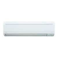
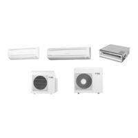
Daikin SUPER MULTI NX FTXS18HVJU Service Manual (285 pages)
Super Multi NX G-Series / J-Series
Brand:
Daikin
| Category:
Air Conditioner
| Size: 18.48 MB
Table of Contents
Table of Contents
2
Safety Considerations
7
Safety Considerations for Repair
7
Safety Considerations for Users
8
Part 1
9
Part
9
List of Functions
9
Functions
10
Part 2
15
Specifications
15
Indoor Unit
16
Outdoor Unit
21
Part 3
24
Part
24
Indoor Unit
25
Ctxs07Jvju, Ctxs09/12Hvju, Ftxs15/18Hvju
25
Ctxs07Lvju, Ftxs09/12Lvju
27
Ftxs15/18Lvju
30
Fdxs09/12Dvju
33
Fdxs09/12Lvju, Cdxs15/18Lvju
35
Outdoor Unit
37
2Mxs18Gvju
37
3Mxs24Jvju, 4Mxs32Gvju
40
Printed Circuit Board Connector Wiring Diagram
24
Part 4
42
Function and Control
42
Part
42
Main Functions
43
Temperature Control
43
Frequency Principle
43
Airflow Direction Control (CTXS/FTXS Series)
45
Fan Speed Control for Indoor Unit
47
Program Dry Operation
48
Automatic Operation
49
Thermostat Control
50
NIGHT SET Mode
52
ECONO Operation
53
HOME LEAVE Operation
54
INTELLIGENT EYE Operation (CTXS/FTXS Series)
55
Inverter POWERFUL Operation
56
Other Functions
57
Function of Thermistor
59
Control Specification
62
Mode Hierarchy
62
Frequency Control
63
Controls at Mode Changing / Start-Up
65
Discharge Pipe Temperature Control
66
Input Current Control
67
Freeze-Up Protection Control
67
Heating Peak-Cut Control
68
Outdoor Fan Control
69
Liquid Compression Protection Function
69
Defrost Control
70
Low Hz High Pressure Limit
71
Outdoor Electronic Expansion Valve Control
71
Pressure Equalizing Control
73
Malfunctions
76
Part 5
78
Operation Manual
78
System Configuration
79
CTXS-J, CTXS-H, FTXS-H Series
80
Remote Controller
80
AUTO · DRY · COOL · HEAT · FAN Operation
82
Adjusting the Airflow Direction
84
INTELLIGENT EYE Operation
86
POWERFUL Operation
88
OUTDOOR UNIT QUIET Operation
89
HOME LEAVE Operation
90
TIMER Operation
92
Note for Multi System
94
CTXS-L, FTXS-L Series
96
Remote Controller
96
AUTO · DRY · COOL · HEAT · FAN Operation
98
Operating Conditions
99
Adjusting the Airflow Direction and Rate
100
COMFORT AIRFLOW / INTELLIGENT EYE Operation
103
POWERFUL Operation
105
OUTDOOR UNIT QUIET Operation
106
ECONO Operation
107
OFF TIMER Operation
108
ON TIMER Operation
109
WEEKLY TIMER Operation
110
Note for Multi System
116
Quick Reference
118
FDXS-D Series
119
Remote Controller
119
AUTO · DRY · COOL · HEAT · FAN Operation
120
POWERFUL Operation
122
OUTDOOR UNIT QUIET Operation
123
HOME LEAVE Operation
124
TIMER Operation
126
CDXS-L, FDXS-L Series
128
Remote Controller
128
AUTO · DRY · COOL · HEAT · FAN Operation
130
Adjusting the Airflow Rate
132
POWERFUL Operation
133
OUTDOOR UNIT QUIET Operation
134
ECONO Operation
135
OFF TIMER Operation
136
ON TIMER Operation
137
Note for Multi System
138
Quick Reference
140
Part 6
141
Service Diagnosis
141
Troubleshooting with LED
143
Indoor Unit
143
Outdoor Unit
144
Problem Symptoms and Measures
145
Service Check Function
146
ARC452 Series Remote Controller
146
ARC433 Series Remote Controller
149
Code Indication on Remote Controller
152
Indoor Unit
152
Outdoor Unit
153
Troubleshooting for Indoor Unit
154
Indoor Unit PCB Abnormality
154
Part
155
Freeze-Up Protection Control or Heating Peak-Cut Control
156
Fan Motor or Related Abnormality
158
Thermistor or Related Abnormality (Indoor Unit)
161
Signal Transmission Error (between Indoor Unit and Outdoor Unit)
162
Unspecified Voltage (between Indoor Unit and Outdoor Unit)
163
Troubleshooting for Outdoor Unit
164
Refrigerant Shortage
164
Low-Voltage Detection or Over-Voltage Detection
167
Signal Transmission Error (on Outdoor Unit PCB) (24/32 Class Only)
169
Unspecified Voltage (between Indoor Unit and Outdoor Unit) / Anti-Icing Function in Other Rooms
170
Anti-Icing Function
171
Outdoor Unit PCB Abnormality (24/32 Class Only)
173
OL Activation (Compressor Overload)
174
Compressor Lock
175
DC Fan Lock
176
Input Overcurrent Detection
177
Four-Way Valve Abnormality (18 Class Only)
178
Four Way Valve Abnormality (18 Class Only)
178
Discharge Pipe Temperature Control
180
High Pressure Control in Cooling
181
Compressor Sensor System Abnormality (24/32 Class Only)
182
Position Sensor Abnormality
184
CT or Related Abnormality
187
Thermistor or Related Abnormality (Outdoor Unit)
189
Electrical Box Temperature Rise
191
Radiation Fin Temperature Rise
194
Output Overcurrent Detection
197
Check
199
Thermistor Resistance Check
199
Fan Motor Connector Check
200
Hall IC Check
200
Power Supply Waveform Check
201
Outdoor Electronic Expansion Valve Check
202
Four Way Valve Performance Check
203
Inverter Unit Refrigerant System Check
203
Inverter Checker" Check
204
Rotation Pulse Check on the Outdoor Unit PCB
205
Installation Condition Check
206
Discharge Pressure Check
206
Outdoor Fan System Check
207
Main Circuit Short Check
207
Capacitor Voltage Check
208
Power Module Check
209
Removal Procedure
210
Part
210
Outdoor Unit: 2MXS18GVJU
211
Removal of Outer Panels
211
Removal of Electrical Box
212
Removal of Pcbs
217
Removal of Fan Motor
220
Removal of Sound Blankets
221
Removal of Coils / Thermistors
223
Removal of Four Way Valve / Defrost Solenoid Valve
225
Removal of Distributor
227
Removal of Compressor
228
Outdoor Unit: 3MXS24JVJU, 4MXS32GVJU
230
Removal of Outer Panels
230
Removal of Electrical Box
242
Removal of Pcbs
248
Removal of Fan Motor
252
Removal of Coils / Thermistors
253
Removal of Sound Blankets
258
Removal of Compressor
261
Part 8
262
Trial Operation and Field Settings
262
Part
262
Pump down Operation
263
Forced Operation
264
Wiring Error Check Function
265
Trial Operation
267
Field Settings
269
Outdoor Unit
269
Indoor Unit
272
Jumper Settings
274
Application of Silicon Grease to a Power Transistor and a Diode Bridge
275
Application of Silicon Grease to Power Transistor and Diode Bridge
275
Part 9
276
Appendix
276
Piping Diagrams
277
Indoor Unit
277
Outdoor Unit
279
Wiring Diagrams
281
Indoor Unit
281
Outdoor Unit
284
Advertisement
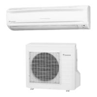
Daikin SUPER MULTI NX FTXS18HVJU Service Manual (274 pages)
Inverter Pair Wall Mounted Type H-Series
Brand:
Daikin
| Category:
Air Conditioner
| Size: 26.48 MB
Table of Contents
Table of Contents
3
Safety Considerations
7
Part 1
10
List of Functions
10
Functions
11
Part 2
13
Specifications
13
SEER 16 Models
14
SEER 13 Models
17
Part
20
Part 3
21
Printed Circuit Board Connector Wiring Diagram
21
Ftxs09/12Hvju
21
Printed Circuit Board Connector Wiring Diagram
22
Ftxs15/18/24Hvju
23
Printed Circuit Board Connector Wiring Diagram
23
Rxs09/12Davju, Rx09/12Favju
25
Rxs15/18/24Dvju, Rx15/18/24Fvju
27
Part
31
Main Functions
33
Frequency Principle
33
Power-Airflow Dual Louvers, Wide-Angle Fins and Auto-Swing
34
Fan Speed Control for Indoor Units
35
Program Dry Function
36
Automatic Operation
37
Thermostat Control
38
NIGHT SET Mode
39
Intelligent Eye
40
HOME LEAVE Operation
41
Inverter POWERFUL Operation
42
Other Functions
43
Function of Thermistor
45
Control Specification (09/12 Class)
46
Mode Hierarchy
46
Frequency Control
46
Control Specification (09/12 Class)
47
Controls at Mode Changing / Start-Up
48
Discharge Pipe Temperature Control
50
Input Current Control
50
Freeze-Up Protection Control
51
Heating Peak-Cut Control
52
Fan Control
52
Liquid Compression Protection Function 2
52
Defrost Control
53
Electronic Expansion Valve Control
54
Malfunctions
57
Forced Operation Mode
58
Additional Functions
58
Forced Operation Mode
59
Control Specification (15/18/24 Class)
59
Mode Hierarchy
59
Frequency Control
60
Control Specification (15/18/24 Class)
60
Controls at Mode Changing / Start-Up
62
Discharge Pipe Temperature Control
63
Input Current Control
63
Freeze-Up Protection Control
64
Heating Peak-Cut Control
64
Fan Control
65
Low Hz High Pressure Limit
65
Liquid Compression Protection Function 2
65
Defrost Control
66
Electronic Expansion Valve Control
67
Malfunctions
69
Forced Operation Mode
71
Additional Functions
71
Part
73
Function and Control
31
Part 5
73
Operation Manual
73
System Configuration
74
Ftxs09/12Hvju
75
Ftxs15/18/24Hvju
88
Part 6
102
Service Diagnosis
102
Caution for Diagnosis
103
Problem Symptoms and Measures
105
Service Check Function
106
Troubleshooting
109
Error Codes and Description
109
Indoor Unit PCB Abnormality
110
Freeze-Up Protection Control or High Pressure Control
111
Fan Motor or Related Abnormality
113
Thermistor or Related Abnormality (Indoor Unit)
116
Signal Transmission Error (between Indoor and Outdoor Unit)
117
OL Activation (Compressor Overload)
119
Compressor Lock
120
DC Fan Lock
122
Input Overcurrent Detection
123
Four-Way Valve Abnormality
126
Discharge Pipe Temperature Control
130
High Pressure Control in Cooling
132
Position Sensor Abnormality
134
DC Voltage / Current Sensor Abnormality
136
CT or Related Abnormality
137
Thermistor or Related Abnormality (Outdoor Unit)
139
Electrical Box Temperature Rise
141
Radiation Fin Temperature Rise
143
Output Overcurrent Detection
145
Refrigerant Shortage
149
Over-Voltage Detection
153
Low-Voltage Detection
154
Check
155
How to Check
155
Four Way Valve Performance Check
156
Thermistor Resistance Check
157
Installation Condition Check
158
Discharge Pressure Check
158
Power Supply Waveforms Check
159
Capacitor Voltage Check
160
Hall IC Check
162
Main Circuit Short Check
163
Part 7
164
Removal Procedure
164
Ftxs09/12Hvju
165
Removal of Air Filter
165
Removal of Front Grille
168
Removal of Horizontal Blades (Louvers) and Vertical Blades (Fins)
171
Removal of Electrical Box, PCB and Swing Motor
173
Removal of Heat Exchanger
179
Install of Drain Plug
182
Removal of Fan Rotor and Fan Motor
184
Ftxs15/18/24Hvju
188
Removal of the Air Filter / Front Panel
188
Removal of Front Grille
192
Removal of Horizontal Blades (Louvers) / Vertical Blades (Fins)
195
Removal of Electrical Box / PCB / Swing Motor
198
Removal of Heat Exchanger
206
Removal of Fan Rotor / Fan Motor
209
Rxs09/12Davju, Rx09/12Favju
212
Removal of Panels and Fan Motor
212
Removal of Electrical Box
221
Removal of Reactor and Partition Plate
225
Removal of Sound Blanket
227
Removal of Four-Way Valve
229
Removal of Compressor
232
Removal of PCB
234
Rxs15/18/24Dvju, Rx15/18/24Fvju
237
Removal of Panels and Plates
237
Removal of Fan Motor / Outdoor Fan
242
Removal of PCB / Electrical Box
246
Removal of the Reactor
255
Removal of Sound Blanket
257
Removal of Four-Way Valve
260
Removal of Electronic Expansion Valve
261
Removal of Compressor
262
Part 8
265
Other Considerations
265
Trial Operation
265
Other Considerations Part
265
Jumper Settings
266
Application of Silicon Grease to Power Transistor and Diode Bridge
267
Part 9
268
Appendix
268
Piping Diagrams
269
Indoor Units
269
Outdoor Units
270
Wiring Diagrams
272
Indoor Units
272
Outdoor Units
273
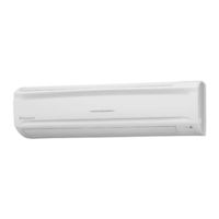
Daikin SUPER MULTI NX FTXS18HVJU Service Manual (244 pages)
Brand:
Daikin
| Category:
Air Conditioner
| Size: 17.25 MB
Table of Contents
Table of Contents
2
Safety Considerations
8
Safety Considerations for Repair
8
Safety Considerations for Users
9
List of Functions
10
Functions
12
Specifications
16
Specifications
18
Indoor Unit
18
Outdoor Unit
20
Printed Circuit Board Connector Wiring Diagram
24
Printed Circuit Board Connector Wiring Diagram
26
Indoor Unit - Duct-Free System
26
Indoor Unit - Slim Duct Built-In System
28
Outdoor Unit - 2MXS18GVJU
30
Outdoor Unit - 3MXS24JVJU, 4MXS32GVJU
33
Function and Control
36
Main Functions
38
Temperature Control
38
Frequency Principle
38
Airflow Direction Control (Duct-Free System)
40
Fan Speed Control for Indoor Units
41
Program Dry Operation
42
Automatic Operation
43
Thermostat Control
44
NIGHT SET Mode
45
HOME LEAVE Operation
46
INTELLIGENT EYE Operation
47
Inverter POWERFUL Operation
48
Other Functions
49
Function of Thermistor
51
Control Specification
53
Mode Hierarchy
53
Frequency Control
54
Controls at Mode Changing / Start-Up
56
Discharge Pipe Temperature Control
58
Input Current Control
58
Freeze-Up Protection Control
59
Heating Peak-Cut Control
59
Outdoor Fan Control
60
Liquid Compression Protection Function
60
Defrost Control
61
Low Hz High Pressure Limit
62
Electronic Expansion Valve Control
62
Malfunctions
66
Forced Operation Mode
68
Operation Manual
70
System Configuration
72
Duct-Free System
73
Remote Controller
73
AUTO · DRY · COOL · HEAT · FAN Operation
75
Adjusting the Airflow Direction
77
INTELLIGENT EYE Operation
79
POWERFUL Operation
81
OUTDOOR UNIT Quiet Operation
82
HOME LEAVE Operation
83
TIMER Operation
85
Note for Multi System
87
Slim Duct Built-In System
89
Remote Controller
89
AUTO / DRY / COOL / HEAT / FAN Operation
90
POWERFUL Operation
92
OUTDOOR UNIT QUIET Operation
93
HOME LEAVE Operation
94
TIMER Operation
96
Service Diagnosis
98
Caution for Diagnosis
100
Troubleshooting with LED
100
Problem Symptoms and Measures
102
Service Check Function
103
ARC452 Series Remote Controller
103
ARC433 Series Remote Controller
106
Code Indication on the Remote Controller
109
Error Codes and Description of Fault
109
Troubleshooting
110
Indoor Unit
110
Outdoor Unit
111
Indoor Unit PCB Abnormality
112
Freeze-Up Protection Control or Heating Peak-Cut Control
113
Fan Motor or Related Abnormality
115
Thermistor or Related Abnormality (Indoor Unit)
118
Signal Transmission Error (between Indoor and Outdoor Units)
119
Unspecified Voltage (between Indoor and Outdoor Units)
121
Anti-Icing Function
122
Outdoor Unit PCB Abnormality (24/32 Class)
124
OL Activation (Compressor Overload)
125
Compressor Lock
126
DC Fan Lock
127
Input Overcurrent Detection
128
Four-Way Valve Abnormality (18 Class)
130
Discharge Pipe Temperature Control
132
High Pressure Control in Cooling
133
Compressor Sensor System Abnormality (24/32 Class)
135
Position Sensor Abnormality
137
CT or Related Abnormality
140
Thermistor or Related Abnormality (Outdoor Unit)
142
Electrical Box Temperature Rise
144
Radiation Fin Temperature Rise
147
Output Overcurrent Detection
150
Refrigerant Shortage
152
Low-Voltage Detection or Over-Voltage Detection
155
Signal Transmission Error (on Outdoor Unit PCB) (24/32 Class)
156
Signal Transmission Error (on Outdoor Unit PCB) (24/32 Class)147
156
Unspecified Voltage (between Indoor and Outdoor Units) / Anti-Icing Function in Other Rooms
157
Tion in Other Rooms
157
Check
158
How to Check
158
Removal Procedure
168
Outdoor Unit - 2MXS18GVJU
170
Removal of the Outer Panels
170
Removal of the Electrical Box
171
Removal of the PCB
175
Removal of the Fan Motor
179
Removal of the Sound Blanket
180
Removal of the Coils and Thermistors
182
Removal of the Four-Way Valve and Defrost Solenoid Valve Procedure
184
Removal of the Compressor
186
Outdoor Unit - 3MXS24JVJU / 4MXS32GVJU
188
Removal of the Outer Panels
188
Removal of the Electrical Box
202
Removal of the PCB
208
Removal of the Fan Motor
213
Removal of the Coils and Thermistors
214
Removal of the Sound Blanket
220
Removal of the Compressor
223
Trial Operation and
224
Field Settings
224
Trial Operation
226
Wiring Error Check Function
228
Field Settings
230
Priority Room Setting
230
COOL / HEAT Mode Lock
230
NIGHT QUIET Mode
231
When 2 Units Are Installed in 1 Room
232
Application of Silicon Grease to a Power Transistor and a Diode Bridge224
233
Appendix
234
Piping Diagrams
236
Indoor Unit
236
Outdoor Unit
237
Wiring Diagrams
239
Indoor Unit
239
Outdoor Unit
241
Advertisement
Daikin SUPER MULTI NX FTXS18HVJU Engineeiring Data (124 pages)
H-Series Heat Pump SEER 13 Models Split-System Room Air Conditioners
Brand:
Daikin
| Category:
Air Conditioner
| Size: 12.87 MB
Table of Contents
Table of Contents
2
1 Power Supply
4
2 Functions
5
3 Specifications
6
4 Dimensions
9
Indoor Units
9
Outdoor Units
11
5 Wiring Diagrams
13
Indoor Units
13
Outdoor Units
14
6 Piping Diagrams
15
Indoor Units
15
Outdoor Units
16
7 Capacity Tables
18
Heat Pump
18
Capacity Correction Factor by the Length of Refrigerant Piping (Reference)
23
8 Operation Limit
24
9 Sound Level
25
Measuring Location
25
Octave Band Level
26
10 Electric Characteristics
30
11 Installation Manual
31
Indoor Units
31
Indoor Unit
32
Wireless Remote Controller
32
Installation Tips
34
Refrigerant Piping Work
37
Outdoor Units
46
Precautions on Installation
48
Installation Guidelines
48
Pump down Operation
51
Outdoor Unit Installation Drawings
55
Outdoor Unit Installation
56
12 Operation Manual
61
Safety Precautions
61
09/12 Class
63
15/18/24 Class
88
Optional Accessories
114
Option List
114
Switch Settings
120
Before Installation
121
Installation Procedure
121
Selection of Installation Location
122
Daikin SUPER MULTI NX FTXS18HVJU Operation Manual (34 pages)
Inverter
Brand:
Daikin
| Category:
Air Conditioner
| Size: 1.69 MB
Table of Contents
Operation Manual
1
Table of Contents
2
Safety Precautions
3
Name of Parts
5
Front Cover
7
Quiet Button
8
Clock Button
8
C/F Display Switch
9
Set Batteries
9
Preparation before Operation
9
AUTO · DRY · COOL · HEAT · FAN Operation
11
Adjusting the Airfl Ow Direction
13
INTELLIGENT EYE Operation
15
POWERFUL Operation
17
OUTDOOR UNIT QUIET Operation
18
HOME LEAVE Operation
19
TIMER Operation
21
Note for Multi System
23
Priority Room Setting
24
Care and Cleaning
25
Trouble Shooting
29
Call the Service Shop Immediately
31
Daikin SUPER MULTI NX FTXS18HVJU Service Manual (23 pages)
REMOVAL PROCEDURE, 15000/18000/24000 Btu/h Class
Brand:
Daikin
| Category:
Air Conditioner
| Size: 2.31 MB
Table of Contents
Table of Contents
3
Removal of Air Filters / Front Panel
4
Removal of Front Grille
6
Removal of Horizontal Blades / Vertical Blades
8
Removal of Electrical Box
10
Removal of Pcbs
12
Removal of Swing Motor
15
Removal of Indoor Heat Exchanger
16
Removal of Fan Rotor / Fan Motor
19
Exchange of Drain Hose (Piping Direction)
21
Advertisement
Related Products
Daikin SUPER MULTI NX FTXS18LVJU
Daikin FTXS18DVJU
Daikin FTXS18SL216
Daikin FTXS18WVJU9
Daikin SUPER MULTI NX FTXS15HVJU
Daikin FTXS12JEVJU
Daikin SUPER MULTI NX FTXS12LVJU
Daikin SUPER MULTI NX FTXS15LVJU
Daikin FTXS100JVMA
Daikin FTXS12SL216
Daikin Categories
Air Conditioner
Heat Pump
Remote Control
Chiller
Fan
More Daikin Manuals
Login
Sign In
OR
Sign in with Facebook
Sign in with Google
Upload manual
Upload from disk
Upload from URL