Table of Contents
Advertisement
Quick Links
Advertisement
Table of Contents
Troubleshooting

Related Manuals for Daikin SUPER MULTI NX G Series


Summary of Contents for Daikin SUPER MULTI NX G Series
- Page 1 SiUS12-928_A G-Series / J-Series [Applied Models] Inverter Multi : Heat Pump...
-
Page 2: Table Of Contents
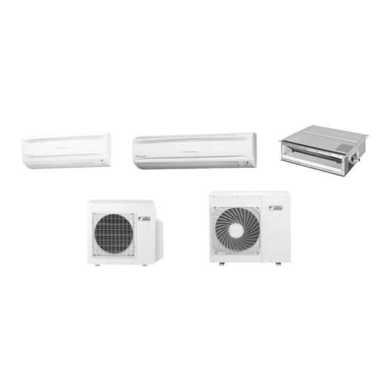
SiUS12-928_A SUPER MULTI NX G-Series / J-Series Heat Pump Indoor Unit CTXS07JVJU CTXS09HVJU CTXS12HVJU FTXS15HVJU FTXS18HVJU FDXS09DVJU FDXS12DVJU Outdoor Unit 2MXS18GVJU 3MXS24JVJU 4MXS32GVJU 1. Safety Considerations................vii 1.1 Safety Considerations for Repair ..............vii 1.2 Safety Considerations for Users..............viii Part 1 List of Functions .............. - Page 3 SiUS12-928_A Part 3 Printed Circuit Board Connector Wiring Diagram ..........15 1. Printed Circuit Board Connector Wiring Diagram........17 1.1 Indoor Unit - Duct-Free System..............17 1.2 Indoor Unit - Slim Duct Built-in System ............19 1.3 Outdoor Unit - 2MXS18GVJU ..............21 1.4 Outdoor Unit - 3MXS24JVJU, 4MXS32GVJU ..........
- Page 4 SiUS12-928_A Part 5 Operation Manual ..............61 1. System Configuration................63 2. Duct-Free System ..................64 2.1 Remote Controller ..................64 2.2 AUTO · DRY · COOL · HEAT · FAN Operation ......... 66 2.3 Adjusting the Airflow Direction..............68 2.4 INTELLIGENT EYE Operation ..............70 2.5 POWERFUL Operation ................
- Page 5 SiUS12-928_A 5.14 Input Overcurrent Detection ..............119 5.15 Four-Way Valve Abnormality (18 Class) ..........121 5.16 Discharge Pipe Temperature Control............123 5.17 High Pressure Control in Cooling ............. 124 5.18 Compressor Sensor System Abnormality (24/32 Class) ......126 5.19 Position Sensor Abnormality ..............128 5.20 CT or Related Abnormality ...............
- Page 6 SiUS12-928_A Part 8 Trial Operation and Field Settings ..............215 1. Trial Operation ..................217 2. Wiring Error Check Function ..............219 3. Field Settings ..................221 3.1 Priority Room Setting ................221 3.2 COOL / HEAT Mode Lock ................ 221 3.3 NIGHT QUIET Mode ................222 3.4 When 2 Units are Installed in 1 Room............
- Page 7 SiUS12-928_A Table of Contents...
-
Page 8: Safety Considerations
Safety Considerations SiUS12-928 1. Safety Considerations Read these SAFETY CONSIDERATIONS carefully before Never use tools or materials designed for R22 performing any repair work. Comply with these safety symbols refrigerant systems on an R410A refrigerant system. without fail.Meanings of DANGER, WARNING, CAUTION, Doing so can cause a serious accident or an and NOTE Symbols: equipment failure. -
Page 9: Safety Considerations For Users
SiUS12-928 Safety Considerations • Do not clean the air conditioner by splashing water on • Check the unit foundation for damage on a continual it. Washing the unit with water may cause an electrical basis, especially if it has been in use for a long time. If shock. -
Page 10: List Of Functions
SiUS12-928_A Part 1 List of Functions 1. Functions.....................3 List of Functions... - Page 11 SiUS12-928_A List of Functions...
-
Page 12: Functions
Functions SiUS12-928 1. Functions Category Functions Category Functions Basic Function Inverter (with Inverter Power Control) Health & Air-Purifying Filter — Clean Operation Limit for Cooling (°FDB) — Operation Limit for Heating (°FWB) — Photocatalytic Deodorizing Filter — Air-Purifying Filter with Photocatalytic ... - Page 13 SiUS12-928 Functions Category Functions Category Functions Basic Function Inverter (with Inverter Power Control) Health & Air Air-Purifying Filter — Cleaning Operation Limit for Cooling (°FDB) — Photocatalytic Deodorizing Filter — Air-Purifying Filter with Photocatalytic Operation Limit for Heating (°FWB) —...
- Page 14 Functions SiUS12-928 Category Functions Category Functions Basic Function Inverter (with Inverter Power Control) Health & Air Air-Purifying Filter — Cleaning Operation Limit for Cooling (°FDB) — Operation Limit for Heating (°FWB) — Photocatalytic Deodorizing Filter — Air-Purifying Filter with Photocatalytic PAM Control —...
- Page 15 SiUS12-928 Functions Category Functions Category Functions Basic Function Inverter (with Inverter Power Control) Health & Clean Air-Purifying Filter — — Operation Limit for Cooling (°FDB) 114.8 114.8 Photocatalytic Deodorizing Filter — — Operation Limit for Heating (°FWB) 59.9 59.9 Air-Purifying Filter with Photocatalytic —...
-
Page 16: Specifications
SiUS12-928_A Part 2 Specifications 1. Specifications ....................9 1.1 Indoor Unit....................9 1.2 Outdoor Unit ....................11 Specifications... - Page 17 SiUS12-928_A Specifications...
-
Page 18: Specifications
Specifications SiUS12-928_A 1. Specifications Indoor Unit Duct-Free System 60 Hz, 208 - 230 V CTXS07JVJU CTXS09HVJU Model Cooling Heating Cooling Heating Rated Capacity 7 kBtu/h Class 9 kBtu/h Class Front Panel Color White White 388 (11.0) 400 (11.3) 388 (11.0) 400 (11.3) Airflow Rates 335 (9.5) - Page 19 SiUS12-928_A Specifications 60 Hz, 230 V FTXS15HVJU FTXS18HVJU Model Cooling Heating Cooling Heating Rated Capacity 15 kBtu/h Class 18 kBtu/h Class Front Panel Color White White 519 (14.7) 515 (14.6) 549 (15.5) 609 (17.2) Airflow Rates 436 (12.3) 459 (13.0) 476 (13.5) 529 (15.0) /min)
-
Page 20: Outdoor Unit
Specifications SiUS12-928_A Outdoor Unit 60 Hz, 208 - 230 V 2MXS18GVJU Model Cooling Heating Capacity — Power Consumption — Running Current — Casing Color Ivory White Type Hermetically Sealed Swing Type Compressor Model 2YC45EXD Motor Output 1,380 Model FVC50K Refrigerant Oil Charge oz (g) 26.5 (751) - Page 21 SiUS12-928_A Specifications 60 Hz, 208 - 230 V 3MXS24JVJU Model Cooling Heating Capacity — Power Consumption — Running Current — Casing Color Ivory White Type Hermetically Sealed Swing Type Compressor Model 2YC63EXD Motor Output 1,920 Model FVC50K Refrigerant Oil Charge 26.5 (751) Type R-410A...
- Page 22 Specifications SiUS12-928_A 60 Hz, 208 - 230 V 4MXS32GVJU Model Cooling Heating Capacity — Power Consumption — Running Current — Casing Color Ivory White Type Hermetically Sealed Swing Type Compressor Model 2YC63EXD Motor Output 1,920 Model FVC50K Refrigerant Oil Charge oz (g) 26.5 (751.3) Type...
- Page 23 SiUS12-928_A Specifications Specifications...
-
Page 24: Printed Circuit Board Connector Wiring Diagram
SiUS12-928_A Part 3 Printed Circuit Board Connector Wiring Diagram 1. Printed Circuit Board Connector Wiring Diagram........13 1.1 Indoor Unit - Duct-Free System..............13 1.2 Indoor Unit - Slim Duct Built-in System ............15 1.3 Outdoor Unit - 2MXS18GVJU ..............17 1.4 Outdoor Unit - 3MXS24JVJU, 4MXS32GVJU .......... - Page 25 SiUS12-928_A Printed Circuit Board Connector Wiring Diagram...
-
Page 26: Printed Circuit Board Connector Wiring Diagram
Printed Circuit Board Connector Wiring Diagram SiUS12-928_A 1. Printed Circuit Board Connector Wiring Diagram Indoor Unit - Duct-Free System Connectors and PCB (1): Control PCB Other Parts 1) S1 Connector for fan motor 2) S6 Connector for swing motor (horizontal blades) 3) S8 Connector for swing motor (vertical blades) 4) S21... - Page 27 SiUS12-928_A Printed Circuit Board Connector Wiring Diagram PCB Detail PCB (1): Control PCB LED A 2P099167-1 PCB (2): Signal Receiver PCB PCB (3): Buzzer PCB 2P099167-1 RTH1 2P099167-1 PCB (4): Display PCB PCB (5): INTELLIGENT EYE Sensor PCB LED1 LED2 LED3 2P099167-1 3P099913-1 Printed Circuit Board Connector Wiring Diagram...
-
Page 28: Indoor Unit - Slim Duct Built-In System
Printed Circuit Board Connector Wiring Diagram SiUS12-928_A Indoor Unit - Slim Duct Built-in System Connectors and PCB (1): Control PCB Other Parts 1) S1 Connector for fan motor 2) S7 Connector for fan motor (Hall IC) 3) S21 Connector for centralized control (HA) 4) S26 Connector for display PCB 5) S32... - Page 29 SiUS12-928_A Printed Circuit Board Connector Wiring Diagram PCB Detail PCB (1): Control PCB LED A 2P131149-1 PCB (2): Display PCB Printed Circuit Board Connector Wiring Diagram...
-
Page 30: Outdoor Unit - 2Mxs18Gvju
Printed Circuit Board Connector Wiring Diagram SiUS12-928_A Outdoor Unit - 2MXS18GVJU Connectors and Main PCB Other Parts 1) S10 Connector for MID1 (indoor - outdoor transmission) 2) S15 Connector for COOL / HEAT mode lock ∗ Refer to page 221 for detail. 3) S20 (white) Connector for electronic expansion valve coil A port 4) S21 (red) - Page 31 SiUS12-928_A Printed Circuit Board Connector Wiring Diagram MID2 (Inverter PCB) 1) S34, S72 Connector for main PCB 2) S70 Connector for outdoor fan motor 3) FU201 Fuse (3.15 A, 250 V) 4) W, V, U, N Connector for compressor 1) CN11, CN14 Connector for main PCB 2) L1, L2 Connector for reactor...
- Page 32 Printed Circuit Board Connector Wiring Diagram SiUS12-928_A MID1 3P080081-2 MID2 (Inverter PCB) FU201 (3.15A) 3P080085-1 CN14 CN11 3EB10032-4 Printed Circuit Board Connector Wiring Diagram...
-
Page 33: Outdoor Unit - 3Mxs24Jvju, 4Mxs32Gvju
SiUS12-928_A Printed Circuit Board Connector Wiring Diagram Outdoor Unit - 3MXS24JVJU, 4MXS32GVJU Connectors and PCB (1): Main PCB Other Parts 1) S10 Connector for terminal board (indoor - outdoor transmission) 2) S15 Connector for COOL / HEAT mode lock ∗ Refer to page 221 for detail. 3) S20 (white) Connector for electronic expansion valve coil A port 4) S21 (red) - Page 34 Printed Circuit Board Connector Wiring Diagram SiUS12-928_A PCB Detail PCB (1): Main PCB (brown) E1 E2 V100 (white) (blue) (blue) S101 2P209947-1 2P209947-2 PCB (2): Service Monitor PCB LED3 LED1 LED4 LED2 LED A S102 3P165332-1 Printed Circuit Board Connector Wiring Diagram...
- Page 35 SiUS12-928_A Printed Circuit Board Connector Wiring Diagram Printed Circuit Board Connector Wiring Diagram...
-
Page 36: Function And Control
SiUS12-928_A Part 4 Function and Control 1. Main Functions..................29 1.1 Temperature Control .................. 29 1.2 Frequency Principle..................29 1.3 Airflow Direction Control (Duct-Free System) ..........31 1.4 Fan Speed Control for Indoor Units............32 1.5 Program Dry Operation ................33 1.6 Automatic Operation................... - Page 37 SiUS12-928_A Function and Control...
-
Page 38: Main Functions
Main Functions SiUS12-928_A 1. Main Functions Temperature Control Definitions of The definitions of temperatures are classified as following. Temperatures Room temperature: temperature of the lower part of the room Set temperature: temperature set by remote controller Room thermistor temperature: temperature detected by room temperature thermistor ... - Page 39 SiUS12-928_A Main Functions Drawing of The following drawing shows a schematic view of the inverter principle: Inverter Refrigerant circulation rate (high) high speed Amount of heat Amount of heat exchanged air (large) exchanged air (large) high f low f Amount of heat Amount of heat exchanged air (small) exchanged air (small)
-
Page 40: Airflow Direction Control (Duct-Free System)
Main Functions SiUS12-928_A Airflow Direction Control (Duct-Free System) Power-Airflow The large louvers send a large volume of air downward to the floor, providing optimum control in cooling, dry, and heating mode. Dual Louvers Cooling / Dry Mode During cooling or dry mode, the louver retracts into the indoor unit. Then, cool air can be blown far and distributed all over the room. -
Page 41: Fan Speed Control For Indoor Units
SiUS12-928_A Main Functions Fan Speed Control for Indoor Units Outline Phase control and fan speed control contains 9 steps: LLL, LL, SL, L, ML, M, MH, H, and HH. The airflow rate can be automatically controlled depending on the difference between the room thermistor temperature and the target temperature. -
Page 42: Program Dry Operation
Main Functions SiUS12-928_A Program Dry Operation Outline Program dry operation removes humidity while preventing the room temperature from lowering. Since the microcomputer controls both the temperature and airflow rate, the temperature adjustment and fan adjustment buttons are inoperable in this mode. Detail The microcomputer automatically sets the temperature and airflow rate. -
Page 43: Automatic Operation
SiUS12-928_A Main Functions Automatic Operation Outline Automatic Cooling / Heating Function When the AUTO mode is selected with the remote controller, the microcomputer automatically determines the operation mode as cooling or heating according to the room temperature and the set temperature at start-up, and automatically operates in that mode. The unit automatically switches the operation mode to maintain the room temperature at the set temperature. -
Page 44: Thermostat Control
Main Functions SiUS12-928_A Thermostat Control Thermostat control is based on the difference between the room thermistor temperature and the target temperature. Thermostat OFF Condition The temperature difference is in zone A. Thermostat ON Condition The temperature difference returns to zone C after being in zone A. ... -
Page 45: Night Set Mode
SiUS12-928_A Main Functions NIGHT SET Mode Outline When the OFF timer is set, the NIGHT SET Mode is automatically activated. The NIGHT SET Mode keeps the airflow rate setting. Detail The NIGHT SET Mode continues operation at the target temperature for the first one hour, then automatically raises the target temperature slightly in the case of cooling, or lowers it slightly in the case of heating. -
Page 46: Home Leave Operation
Main Functions SiUS12-928_A HOME LEAVE Operation Outline HOME LEAVE operation is a function that allows you to record your favorite set temperature and airflow rate. You can start your favorite operation mode simply by pressing the [HOME LEAVE] button on the remote controller. Detail 1. -
Page 47: Intelligent Eye Operation
SiUS12-928_A Main Functions 1.10 INTELLIGENT EYE Operation Outline This is the function that detects existence of humans in the room by a human motion sensor (INTELLIGENT EYE) and reduces the capacity when there is nobody in the room in order to save electricity. -
Page 48: Inverter Powerful Operation
Main Functions SiUS12-928_A 1.11 Inverter POWERFUL Operation Outline In order to maximize the benefits of the cooling and heating capacity, operate the air conditioner by increasing the indoor fan rotating speed and the compressor frequency. Detail When POWERFUL button is pressed, the fan speed and target temperature are converted to the following states for 20 minutes. -
Page 49: Other Functions
SiUS12-928_A Main Functions 1.12 Other Functions 1.12.1 Hot-Start Function In order to prevent the cold air blast that normally comes when heating operation is started, the temperature of the indoor heat exchanger is detected, and the airflow is either stopped or reduced, thereby carrying out comfortable heating of the room. - Page 50 Main Functions SiUS12-928_A 1.12.4 Air-Purifying Filter with Photocatalytic Deodorizing Function Duct-Free System Only This filter incorporates the benefits of a Air-Purifying Filter and Photocatalytic Deodorizing Filter in a single unit. Combining the two filters in this way increases the active surface area of the new filter. This larger surface area allows the filter to effectively trap microscopic particles, decompose odors and eliminate bacteria and viruses even in large living rooms.
-
Page 51: Function Of Thermistor
SiUS12-928_A Function of Thermistor 2. Function of Thermistor <2MXS18GVJU> Expansion valve Receiver Defrost solenoid valve Four-way valve Compressor <3MXS24JVJU> Expansion valve Four way valve (R12405) Compressor <4MXS32GVJU> Expansion valve Four-way valve Compressor (R5067) Function and Control... - Page 52 Function of Thermistor SiUS12-928_A A Outdoor Heat 1. The outdoor heat exchanger thermistor is used for controlling target discharge pipe temperature. The system sets the target discharge pipe temperature according to the outdoor Exchanger and indoor heat exchanger temperature, and controls the electronic expansion valve opening so Thermistor that the target discharge pipe temperature can be obtained.
-
Page 53: Control Specification
SiUS12-928_A Control Specification 3. Control Specification Mode Hierarchy Outline There are two modes; the one is the normal operation mode and the other is the forced operation mode for installation and providing service. Detail There are the following modes; stop, cooling (includes drying), heating (includes defrosting) Air conditioner control mode Forced operation mode Forced cooling... -
Page 54: Frequency Control
Control Specification SiUS12-928_A Frequency Control Outline Frequency that corresponds to each room’s capacity is determined according to the difference between the target temperature and the thermistor temperature of each room. The function is explained as follows. 1. How to determine frequency 2. - Page 55 SiUS12-928_A Control Specification Indoor Frequency Command (ΔD signal) The difference between a room thermistor temperature and the target temperature is taken as the “ΔD signal” and is used for frequency command. ΔD ΔD ΔD ΔD Temperature Temperature Temperature Temperature difference signal difference signal...
-
Page 56: Controls At Mode Changing / Start-Up
Control Specification SiUS12-928_A Controls at Mode Changing / Start-up 3.3.1 Preheating Operation Outline The inverter operation in open phase starts with the conditions of the preheating command from the indoor and outdoor temperatures, and the discharge pipe temperature. Details ON Condition ... - Page 57 SiUS12-928_A Control Specification 3.3.4 3-Minute Standby Turning on the compressor is prohibited for 3 minutes after turning off. (Except when defrosting.) 3.3.5 Compressor Protection Function When turning the compressor from OFF to ON, the upper limit of frequency is set as follows. (The function is not used when defrosting.) (Hz) Frequency...
-
Page 58: Discharge Pipe Temperature Control
Control Specification SiUS12-928_A Discharge Pipe Temperature Control Outline The discharge pipe temperature is used as the internal temperature of the compressor. If the discharge pipe temperature rises above a certain level, the upper limit of frequency is set to keep this temperature from going up further. -
Page 59: Freeze-Up Protection Control
SiUS12-928_A Control Specification Freeze-up Protection Control Outline During cooling operation, the signals sent from the indoor unit allow the operating frequency limitation and prevent freezing of the indoor heat exchanger. (The signal from the indoor unit is divided into zones.) Details The operating frequency limitation is judged with the indoor heat exchanger temperature 2 seconds after operation starts and 30 seconds after the number of operation room is changed. -
Page 60: Outdoor Fan Control
Control Specification SiUS12-928_A Outdoor Fan Control 1. Fan OFF delay when stopped The outdoor fan is turned OFF 60 seconds after the compressor stops. 2. Fan ON control to cool down the electrical box The outdoor fan is turned ON when the electrical box temperature is high while the compressor is OFF. -
Page 61: Defrost Control
SiUS12-928_A Control Specification 3.10 Defrost Control Outline Defrosting is carried out by the cooling cycle (reverse cycle). The defrosting time or outdoor heat exchanger temperature must be more than a certain value to finish. Detail Conditions for Starting Defrost The starting conditions are determined with the outdoor temperature and the outdoor heat exchanger temperature. -
Page 62: Low Hz High Pressure Limit
Control Specification SiUS12-928_A 3.11 Low Hz High Pressure Limit Outline The upper limit of high pressure in a low Hz zone is set. The upper limit of the indoor heat exchanger temperature is also set by the operating frequency. There are 3 zones. Reset zone, keep zone, and dropping zone, and the frequency control is carried out according to each zone. - Page 63 SiUS12-928_A Control Specification Detail The following are examples of control which function in each mode by the electronic expansion valve control. Operation pattern : function × : not function When power is turned on × × × × × ×...
- Page 64 Control Specification SiUS12-928_A 3.12.1 Fully Closing with Power on The electronic expansion valve is initialized when the power is turned on. The opening position is set and the pressure equalization is developed. 3.12.2 Pressure Equalization Control When the compressor is stopped, pressure equalization control is activated. The electronic expansion valve opens, and develops pressure equalization.
- Page 65 SiUS12-928_A Control Specification 3.12.8 Target Discharge Pipe Temperature Control The target discharge pipe temperature is obtained from the indoor and outdoor heat exchanger temperature, and the electronic expansion valve opening is adjusted so that the actual discharge pipe temperature becomes close to the target discharge pipe temperature. (Indirect SH (superheat) control using the discharge pipe temperature).
-
Page 66: Malfunctions
Control Specification SiUS12-928_A Detail Detect Disconnection When the starting control (630 seconds) finishes, and the 9-minute timer for the compressor operation continuation is not counting time, the following adjustment is made. 1. When the operation mode is cooling When the discharge pipe temperature is lower than the outdoor heat exchanger temperature, the discharge pipe thermistor disconnection is ascertained. - Page 67 SiUS12-928_A Control Specification 3.13.3 Refrigerant Shortage Control Outline I Detecting by power consumption If the power consumption is below the specified value and the frequency is higher than the specified frequency, it is regarded as refrigerant shortage. The power consumption is small comparing with that in the normal operation when refrigerant is insufficient, and refrigerant shortage is detected by checking a power consumption.
-
Page 68: Forced Operation Mode
Control Specification SiUS12-928_A 3.14 Forced Operation Mode Outline Forced operation mode includes forced cooling and forced heating. Operation mode can be selected by the operation mode switch (SW2) on the outdoor unit. Press the forced operation ON/OFF switch (SW1) on the outdoor unit to start the operation. Detail Forced Cooling, Forced Heating Item... - Page 69 SiUS12-928_A Control Specification Function and Control...
-
Page 70: Operation Manual
SiUS12-928_A Part 5 Operation Manual 1. System Configuration................63 2. Duct-Free System ..................64 2.1 Remote Controller ..................64 2.2 AUTO · DRY · COOL · HEAT · FAN Operation ......... 66 2.3 Adjusting the Airflow Direction..............68 2.4 INTELLIGENT EYE Operation ..............70 2.5 POWERFUL Operation ................ - Page 71 SiUS12-928_A Operation Manual...
-
Page 72: System Configuration
System Configuration SiUS12-928_A 1. System Configuration After installation and test operation of the room air conditioner are completed, the air conditioner should be handled and operated as described the following pages. Every user should be informed on the correct method of operation and how to check if it can cool (or heat) well and how to use it most efficiently. -
Page 73: Duct-Free System
SiUS12-928_A Duct-Free System 2. Duct-Free System Remote Controller Operation Manual... - Page 74 Duct-Free System SiUS12-928_A Selects the operation mode. INTELLIGENT EYE operation Cancels the timer setting. Changes the ON/OFF Operation Manual...
-
Page 75: Auto · Dry · Cool · Heat · Fan Operation
SiUS12-928_A Duct-Free System AUTO · DRY · COOL · HEAT · FAN Operation The air conditioner operates with the operation mode of your choice. From the next time on, the air conditioner will operate with the same operation mode. To start operation 1. - Page 76 Duct-Free System SiUS12-928_A To change the air flow rate setting 5. Press “FAN setting button”. DRY mode AUTO or COOL or HEAT or FAN mode Five levels of air flow rate setting from “ ” to “ ” plus “ ”...
-
Page 77: Adjusting The Airflow Direction
SiUS12-928_A Duct-Free System Adjusting the Airflow Direction To adjust the louvers (horizontal blades) is displayed on the LCD and the louvers begin to swing. When the louvers have reached the desired position, The louvers will stop moving. is no longer displayed on the LCD. To adjust the fins (vertical blades) When the fins have reached the desired The fins will stop moving. - Page 78 Duct-Free System SiUS12-928_A Using 3-D airflow circulates cool or warm air to prevent the accumulation of too much cool air on the floor of a room or too much warm air rising to the room’s ceiling, assuring a more even distribution of air.
-
Page 79: Intelligent Eye Operation
SiUS12-928_A Duct-Free System INTELLIGENT EYE Operation is displayed on the LCD. is no longer displayed on the LCD. detecting movement. The set temperature is shifted in detects movement again. Operation Manual... - Page 80 Duct-Free System SiUS12-928_A and light reflected off the mirrors on passing vehicles. operation COMFORT AIRFLOW Do not place large objects near the sensor. Also, keep heating units or humidifiers outside the sensor’s detection area. This sensor can detect undesirable objects. Do not hit or forcibly push the INTELLIGENT EYE sensor.
-
Page 81: Powerful Operation
SiUS12-928_A Duct-Free System POWERFUL Operation is no longer displayed on the LCD. is no longer displayed on the LCD. Operation Manual... -
Page 82: Outdoor Unit Quiet Operation
Duct-Free System SiUS12-928_A OUTDOOR UNIT Quiet Operation is no longer displayed on the LCD. Operation Manual... -
Page 83: Home Leave Operation
SiUS12-928_A Duct-Free System HOME LEAVE Operation is no longer displayed on the LCD. Operation Manual... - Page 84 Duct-Free System SiUS12-928_A Operation Manual...
-
Page 85: Timer Operation
SiUS12-928_A Duct-Free System TIMER Operation Operation Manual... - Page 86 Duct-Free System SiUS12-928_A Operation Manual...
-
Page 87: Note For Multi System
SiUS12-928_A Duct-Free System Note for Multi System Operation Manual... - Page 88 Duct-Free System SiUS12-928_A Operation Manual...
-
Page 89: Slim Duct Built-In System
SiUS12-928_A Slim Duct Built-In System 3. Slim Duct Built-In System Remote Controller Remote Controller 〈 ARC433B63 〉 1. Signal transmitter: 7. MODE selector button: • It sends signals to the indoor unit. • It selects the operation mode. (AUTO/DRY/COOL/HEAT/FAN) (page 10.) 2. -
Page 90: Auto / Dry / Cool / Heat / Fan Operation
Slim Duct Built-In System SiUS12-928_A AUTO / DRY / COOL / HEAT / FAN Operation The air conditioner operates with the operation mode of your choice. From the next time on, the air conditioner will operate with the same operation mode. To start operation 1. - Page 91 SiUS12-928_A Slim Duct Built-In System To change the air flow rate setting 5. Press “FAN setting button”. DRY mode AUTO or COOL or HEAT or FAN mode Five levels of air flow rate setting from “ ” to “ ” plus “...
-
Page 92: Powerful Operation
Slim Duct Built-In System SiUS12-928_A POWERFUL Operation POWERFUL operation quickly maximizes the cooling (heating) effect in any operation mode. You can get the maximum capacity. To start POWERFUL operation 1. Press “POWERFUL button”. • POWERFUL operation ends in 20 minutes. Then the system automatically operates again with the settings which were used before POWERFUL operation. -
Page 93: Outdoor Unit Quiet Operation
SiUS12-928_A Slim Duct Built-In System OUTDOOR UNIT QUIET Operation OUTDOOR UNIT QUIET operation lowers the sound levels of the outdoor unit by changing the frequency and fan speed on the outdoor unit. This function is convenient during night. To start OUTDOOR UNIT QUIET operation 1. -
Page 94: Home Leave Operation
Slim Duct Built-In System SiUS12-928_A HOME LEAVE Operation HOME LEAVE operation is a function which allows you to record your preferred temperature and air flow rate settings. To start HOME LEAVE operation 1. Press “HOME LEAVE button”. • “ ” is displayed on the LCD. •... - Page 95 SiUS12-928_A Slim Duct Built-In System What’s the HOME LEAVE operation? Is there a set temperature and air flow rate that is most comfortable, a set temperature and air flow rate that you use the most? HOME LEAVE operation is a function that allows you to record your favorite set temperature and air flow rate.
-
Page 96: Timer Operation
Slim Duct Built-In System SiUS12-928_A TIMER Operation TIMER Operation Timer functions are useful for automatically switching the air conditioner on or off at night or in the morning. You can also use OFF TIMER and ON TIMER in combination. To use OFF TIMER operation •... - Page 97 SiUS12-928_A Slim Duct Built-In System Operation Manual...
-
Page 98: Service Diagnosis
SiUS12-928_A Part 6 Service Diagnosis 1. Caution for Diagnosis................91 1.1 Troubleshooting with LED ................91 2. Problem Symptoms and Measures ............93 3. Service Check Function ................94 3.1 ARC452 Series Remote Controller ............94 3.2 ARC433 Series Remote Controller ............97 4. - Page 99 SiUS12-928_A Service Diagnosis...
-
Page 100: Caution For Diagnosis
Caution for Diagnosis SiUS12-928_A 1. Caution for Diagnosis Troubleshooting with LED Indoor unit The operation lamp blinks when any of the following errors is detected. 1. When a protection device of the indoor or outdoor unit is activated, or when the thermistor malfunctions. - Page 101 SiUS12-928_A Caution for Diagnosis Outdoor Unit Service monitor PCB LED A 2MXS18GVJU LED 1 LED 2 LED 3 LED 4 3MXS24JVJU (R6333) 4MXS32GVJU There are a green LED (LED A) and red LEDs (LED 1- LED 4) on the outdoor unit PCB. The LED A indicates microcomputer operation condition.
-
Page 102: Problem Symptoms And Measures
Problem Symptoms and Measures SiUS12-928_A 2. Problem Symptoms and Measures Symptom Check Item Details of Measure Reference Page None of the units operates. Check the power supply. Check to make sure that the rated voltage is — supplied. Check the type of the indoor units. Check to make sure that the indoor unit type is —... -
Page 103: Service Check Function
SiUS12-928_A Service Check Function 3. Service Check Function ARC452 Series Remote Controller Check Method 1 1. When the timer cancel button is held down for 5 seconds, “00” indication is displayed on the temperature display section. <Open the front cover> TIMER CANCEL b utton <... - Page 104 Service Check Function SiUS12-928_A Check Method 2 , TEMP , MODE) at the same time. 1. Press the 3 buttons (TEMP (R8381) The left-side digit blinks. (R9430) or button and change the figure until you hear the sound of beep or beep- 2.
- Page 105 SiUS12-928_A Service Check Function or button and change the figure until you hear the beep. 5. Press the TEMP (R8383) 6. Diagnose by the sound. beep : The left digit does not correspond with the error code. beep beep : The left digit corresponds with the error code but the right side digit does not. long beep : Both digits correspond with the error code.
-
Page 106: Arc433 Series Remote Controller
Service Check Function SiUS12-928_A ARC433 Series Remote Controller Check Method 1 1. When the timer cancel button is held down for 5 seconds, “00” indication appears on the temperature display section. TIMER CANCEL button < ARC433 Series > (R11506) 2. Press the timer cancel button repeatedly until a long beep sounds. ... - Page 107 SiUS12-928_A Service Check Function Check Method 2 1. Press the center of the TEMP button and the MODE button at the same time. (R4272) The left-side digit blinks. (R4273) or button and change the figure until you hear the beep 2.
- Page 108 Service Check Function SiUS12-928_A or button and change the figure until you hear the beep. 5. Press the TEMP (R4277) 6. Diagnose by the sound. beep : The left digit does not correspond with the error code. beep beep : The left digit corresponds with the error code but the right-side digit does not. “long beep”...
-
Page 109: Code Indication On The Remote Controller
SiUS12-928_A Code Indication on the Remote Controller 4. Code Indication on the Remote Controller Error Codes and Description of Fault Error Codes Description of Fault System Normal Refrigerant shortage Low-voltage detection or over-voltage detection Signal transmission error (between indoor and outdoor units) Signal transmission error (on outdoor unit PCB) Unspecified voltage (between indoor and outdoor units) Anti-icing function in other rooms... -
Page 110: Troubleshooting
Troubleshooting SiUS12-928_A 5. Troubleshooting Indoor Unit Error Codes Description of Fault Reference Page Normal condition — Indoor unit PCB abnormality Freeze-up protection control or heating peak-cut control AC motor (Slim duct built-in) Fan motor or related abnormality DC motor (Duct-free) Indoor heat exchanger thermistor or related abnormality Room temperature thermistor or related abnormality Signal transmission error (between indoor and outdoor units) -
Page 111: Outdoor Unit
SiUS12-928_A Troubleshooting Outdoor Unit : ON, : OFF, : Blinks Normal condition : Green - blinks, Red - OFF Outdoor Unit LED Indication Error Codes Description of Fault Reference Green Page 3 00 Normal condition — Unspecified voltage (between indoor and outdoor units) Anti-icing function in other rooms (U0) Refrigerant shortage... -
Page 112: Indoor Unit Pcb Abnormality
Troubleshooting SiUS12-928_A Indoor Unit PCB Abnormality Remote Controller Display Method of Evaluation of zero-cross detection of power supply by the indoor unit PCB. Malfunction Detection Malfunction There is no zero-cross detection in approximately 10 seconds. Decision Conditions Wrong models interconnected Supposed ... -
Page 113: Freeze-Up Protection Control Or Heating Peak-Cut Control
SiUS12-928_A Troubleshooting Freeze-up Protection Control or Heating Peak-cut Control Remote Controller Display Freeze-up protection control Method of Malfunction During cooling operation, the freeze-up protection control (operation halt) is activated according to the temperature detected by the indoor heat exchanger thermistor. Detection ... - Page 114 Troubleshooting SiUS12-928_A Troubleshooting Be sure to turn off the power switch before connecting or disconnecting Caution connectors, or parts may be damaged. Check No.06 Refer to P.152 Check the air passage. Provide sufficient air passage. Are there any short circuits? Check the air filter.
-
Page 115: Fan Motor Or Related Abnormality
SiUS12-928_A Troubleshooting Fan Motor or Related Abnormality 5.5.1 AC Motor (Slim Duct Built-in System) Remote Controller Display Method of The rotation speed detected by the Hall IC during fan motor operation is used to determine Malfunction abnormal fan motor operation. Detection Malfunction The detected rotation speed does not reach the demanded rotation speed of the target tap, and is... - Page 116 Troubleshooting SiUS12-928_A 5.5.2 DC Motor (Duct-Free System) Remote Controller Display Method of The rotation speed detected by the Hall IC during fan motor operation is used to determine Malfunction abnormal fan motor operation. Detection Malfunction The detected rotation speed does not reach the demanded rotation speed of the target tap, and is Decision less than 50% of the maximum fan motor rotation speed.
- Page 117 SiUS12-928_A Troubleshooting Troubleshooting Be sure to turn off the power switch before connecting or disconnecting Caution connectors, or parts may be damaged. Check No.01 Turn off the power supply Refer to P.149 and rotate the fan by hand. Does the fan rotate Replace the fan smoothly? motor.
-
Page 118: Thermistor Or Related Abnormality (Indoor Unit)
Troubleshooting SiUS12-928_A Thermistor or Related Abnormality (Indoor Unit) C4, C9 Remote Controller Display Method of The temperatures detected by the thermistors are used to determine thermistor errors. Malfunction Detection Malfunction The thermistor input is more than 4.96 V or less than 0.04 V during compressor operation. Decision Conditions ... -
Page 119: Signal Transmission Error (Between Indoor And Outdoor Units)
SiUS12-928_A Troubleshooting Signal Transmission Error (between Indoor and Outdoor Units) Remote Controller Display Method of The data received from the outdoor unit in indoor unit-outdoor unit signal transmission is checked Malfunction whether it is normal. Detection Malfunction The data sent from the outdoor unit cannot be received normally, or the content of the data is abnormal. - Page 120 Troubleshooting SiUS12-928_A Troubleshooting Be sure to turn off the power switch before connecting or disconnecting Caution connectors, or parts may be damaged. Check No.10 Check the indoor unit - outdoor Refer to P.155 unit connection wires. Is there any wiring error? Correct the indoor unit - outdoor unit connection wires.
-
Page 121: Unspecified Voltage (Between Indoor And Outdoor Units)
SiUS12-928_A Troubleshooting Unspecified Voltage (between Indoor and Outdoor Units) Remote Controller Display Method of The supply power is detected for its requirements (different from pair type and multi type) by the Malfunction indoor / outdoor transmission signal. Detection Malfunction The pair type and multi type are interconnected. Decision Conditions ... -
Page 122: Anti-Icing Function
Troubleshooting SiUS12-928_A Anti-icing Function Remote Controller Display Outdoor Unit LED Display Method of During cooling operation, indoor unit icing is detected by checking the temperatures sensed by the Malfunction indoor heat exchanger thermistor and the room temperature thermistor that are located in a shut- down room. - Page 123 SiUS12-928_A Troubleshooting Troubleshooting Be sure to turn off the power switch before connecting or disconnecting Caution connectors, or parts may be damaged. Check No.04 Refer to P.150 Check the wiring and piping. Check No.06 Wrong wiring or Activate the wiring error check piping? Refer to P.152 mode.
-
Page 124: Outdoor Unit Pcb Abnormality (24/32 Class)
Troubleshooting SiUS12-928_A 5.10 Outdoor Unit PCB Abnormality (24/32 Class) Remote Controller Display Outdoor Unit LED Display Method of Detect within the program of the microcomputer. Malfunction Detection Malfunction The program of the microcomputer is in abnormal running order. Decision Conditions ... -
Page 125: Ol Activation (Compressor Overload)
SiUS12-928_A Troubleshooting 5.11 OL Activation (Compressor Overload) Remote Controller Display Outdoor Unit LED Display Method of A compressor overload is detected through compressor OL. Malfunction Detection If the error repeats twice, the system is shut down. Malfunction Reset condition: Continuous run for about 60 minutes without any other error Decision ∗... -
Page 126: Compressor Lock
Troubleshooting SiUS12-928_A 5.12 Compressor Lock Remote Controller Display Outdoor Unit LED Display Method of A compressor lock is detected by checking the compressor running condition through the position Malfunction detection circuit. Detection Judging from the current waveform generated when high-frequency voltage is applied to the Malfunction Decision compressor. -
Page 127: Dc Fan Lock
SiUS12-928_A Troubleshooting 5.13 DC Fan Lock Remote Controller Display Outdoor Unit LED Display Method of An error is determined with the high-voltage fan motor rotation speed detected by the Hall IC. Malfunction Detection The fan does not start in 30 seconds even when the fan motor is running. Malfunction ... -
Page 128: Input Overcurrent Detection
Troubleshooting SiUS12-928_A 5.14 Input Overcurrent Detection Remote Controller Display Outdoor Unit LED Display Method of Detected by checking the input current value Malfunction Detection The input current is at a certain value (depending on the condition) for 2.5 seconds. Malfunction ... - Page 129 SiUS12-928_A Troubleshooting Troubleshooting Be sure to turn off the power switch before connecting or disconnecting Caution connectors, or parts may be damaged. Check No.07 ∗ An input overcurrent may result from wrong internal wiring. If the wires have been disconnected and Refer to P.153 reconnected, and the system is interrupted by an input overcurrent, take the following procedure.
-
Page 130: Four-Way Valve Abnormality (18 Class)
Troubleshooting SiUS12-928_A 5.15 Four-Way Valve Abnormality (18 Class) Remote Controller Display Outdoor Unit LED Display Method of The liquid pipe thermistor, the outdoor temperature thermistor and the outdoor heat exchanger Malfunction thermistor are checked to see if they function within their normal ranges in the operating mode. Detection Malfunction Either of the following conditions occurs 6 minutes after the compressor has started. - Page 131 SiUS12-928_A Troubleshooting Troubleshooting Be sure to turn off the power switch before connecting or disconnecting Caution connectors, or parts may be damaged. Check No.05 Refer to P.151 Four way valve coil Correct it. disconnected (loose)? Check No.06 Refer to P.152 Harness out of connector? Reconnect it.
-
Page 132: Discharge Pipe Temperature Control
Troubleshooting SiUS12-928_A 5.16 Discharge Pipe Temperature Control Remote Controller Display Outdoor Unit LED Display Method of Detected by the discharge pipe thermistor Malfunction Detection If the temperature detected by the discharge pipe thermistor rises above Malfunction , the compressor Decision stops. -
Page 133: High Pressure Control In Cooling
SiUS12-928_A Troubleshooting 5.17 High Pressure Control in Cooling Remote Controller Display Outdoor Unit LED Display Method of High-pressure control (operation halt, frequency drop, etc.) is activated in cooling mode if the Malfunction temperature sensed by the outdoor heat exchanger thermistor exceeds the limit. Detection ... - Page 134 Troubleshooting SiUS12-928_A Troubleshooting Be sure to turn off the power switch before connecting or disconnecting Caution connectors, or parts may be damaged. Check No.04 Check the installation space. Refer to P.150 Check No.06 Check No. 07 Change the installation Check the installation Refer to P.152 location or direction.
-
Page 135: Compressor Sensor System Abnormality (24/32 Class)
SiUS12-928_A Troubleshooting 5.18 Compressor Sensor System Abnormality (24/32 Class) Remote Controller Display Outdoor Unit LED Display Fault condition is identified by the supply voltage and the DC voltage which is detected before Method of the compressor startup. Malfunction Fault condition is identified by the compressor current which is detected right after the Detection compressor startup. - Page 136 Troubleshooting SiUS12-928_A Troubleshooting Be sure to turn off the power switch before connecting or disconnecting Caution connectors, or parts may be damaged. Turn off the power. Reactor connection check Connection OK? Connect properly. Compressor connection check Connect properly. Connection OK? Disconnect the reactor from the outdoor unit PCB and measure the resistance Reactor check...
-
Page 137: Position Sensor Abnormality
SiUS12-928_A Troubleshooting 5.19 Position Sensor Abnormality Remote Controller Display Outdoor Unit LED Display Method of A compressor startup failure is detected by checking the compressor running condition through the position detection circuit. Malfunction Detection If the error repeats 8 times, the system is shut down. Malfunction ... - Page 138 Troubleshooting SiUS12-928_A Troubleshooting 18 class Be sure to turn off the power switch before connecting or disconnecting Caution connectors, or parts may be damaged. Check No.29 Refer to P.158 Turn off the power. Check the power supply voltage. Voltage as rated? Correct the power supply.
- Page 139 SiUS12-928_A Troubleshooting Troubleshooting 24/32 class Be sure to turn off the power switch before connecting or disconnecting Caution connectors, or parts may be damaged. Turn off the power. Check the power supply voltage. Voltage as rated? Correct the power supply. Check the connection.
-
Page 140: Ct Or Related Abnormality
Troubleshooting SiUS12-928_A 5.20 CT or Related Abnormality Remote Controller Display Outdoor Unit LED Display Method of A CT or related error is detected by checking the compressor running frequency and CT-detected Malfunction input current. Detection The compressor running frequency is more than Malfunction Hz and input current is below Decision... - Page 141 SiUS12-928_A Troubleshooting Troubleshooting Be sure to turn off the power switch before connecting or disconnecting Caution connectors, or parts may be damaged. Check No.12 Turn off the power and turn it on Refer to P.156 again. Start operation. ∗ Running current as shown at Replace the outdoor unit right with relay cable 1...
-
Page 142: Thermistor Or Related Abnormality (Outdoor Unit)
Troubleshooting SiUS12-928_A 5.21 Thermistor or Related Abnormality (Outdoor Unit) H9, J3, J6, J8, J9, P4 Remote Controller Display Outdoor Unit LED Display Method of This type of error is detected by checking the thermistor input voltage to the microcomputer. Malfunction A thermistor error is detected by checking the temperature sensed by each thermistor. - Page 143 SiUS12-928_A Troubleshooting Troubleshooting Be sure to turn off the power switch before connecting or disconnecting Caution connectors, or parts may be damaged. Turn on the power again. Check No.06 Refer to P.152 Error displayed Reconnect the connectors again on remote or thermistors.
-
Page 144: Electrical Box Temperature Rise
Troubleshooting SiUS12-928_A 5.22 Electrical Box Temperature Rise Remote Controller Display Outdoor Unit LED Display Method of An electrical box temperature rise is detected by checking the radiation fin thermistor with the Malfunction compressor off. Detection With the compressor off, the radiation fin temperature is above Malfunction ... - Page 145 SiUS12-928_A Troubleshooting Troubleshooting 18 class Be sure to turn off the power switch before connecting or disconnecting Caution connectors, or parts may be damaged. Check No.06 WARNING Turn off the power and turn it on Refer to P.152 again. To cool the electrical components, the outdoor fan starts when the radiation fin temperature rises above...
- Page 146 Troubleshooting SiUS12-928_A Troubleshooting 24/32 class Be sure to turn off the power switch before connecting or disconnecting Caution connectors, or parts may be damaged. Check No.07 WARNING Turn off the power and turn it on Refer to P.153 again. To cool the electrical components, the outdoor fan starts when the radiation fin temperature rises above...
-
Page 147: Radiation Fin Temperature Rise
SiUS12-928_A Troubleshooting 5.23 Radiation Fin Temperature Rise Remote Controller Display Outdoor Unit LED Display Method of A radiation fin temperature rise is detected by checking the radiation fin temperature with the Malfunction compressor on. Detection The radiation fin temperature with the compressor on is above Malfunction ... - Page 148 Troubleshooting SiUS12-928_A Troubleshooting 18 class Be sure to turn off the power switch before connecting or disconnecting Caution connectors, or parts may be damaged. (Precaution before turning on the power again) Check No.06 Make sure the power has been off for at least 30 seconds. Refer to P.152 Turn off the power and turn it on Check No.07...
- Page 149 SiUS12-928_A Troubleshooting Troubleshooting 24/32 class Be sure to turn off the power switch before connecting or disconnecting Caution connectors, or parts may be damaged. Check No.07 Turn off the power and turn it on Refer to P.153 again to start the system. Check No.09 Refer to P.154 Error displayed again?
-
Page 150: Output Overcurrent Detection
Troubleshooting SiUS12-928_A 5.24 Output Overcurrent Detection Remote Controller Display Outdoor Unit LED Display Method of An output overcurrent is detected by checking the current that flows in the inverter DC section. Malfunction Detection A position signal error occurs while the compressor is running. Malfunction ... - Page 151 SiUS12-928_A Troubleshooting Troubleshooting Be sure to turn off the power switch before connecting or disconnecting Caution connectors, or parts may be damaged. ∗ An output overcurrent signal may result from wrong internal wiring. If the wires have been Check No.07 disconnected and reconnected and the system is interrupted by an output overcurrent, take the following procedure.
-
Page 152: Refrigerant Shortage
Troubleshooting SiUS12-928_A 5.25 Refrigerant Shortage Remote Controller Display Outdoor Unit LED Display Method of Refrigerant shortage detection I : Malfunction Refrigerant shortage is detected by checking the input current value and the compressor output frequency. If the refrigerant is short, the input current is smaller than the normal value. Detection Refrigerant shortage detection II : Refrigerant shortage is detected by checking the discharge pipe temperature and the opening of... - Page 153 SiUS12-928_A Troubleshooting Troubleshooting 18 class Be sure to turn off the power switch before connecting or disconnecting Caution connectors, or parts may be damaged. Check No.04 Refer to P.150 Any thermistor Replace them in position. disconnected? * Discharge pipe thermistor * Indoor or outdoor heat exchanger thermistor * Room temperature thermistor Check No.06...
- Page 154 Troubleshooting SiUS12-928_A Troubleshooting 24/32 class Be sure to turn off the power switch before connecting or disconnecting Caution connectors, or parts may be damaged. Check No.04 Refer to P.150 Any thermistor Replace them in position. disconnected? * Discharge pipe thermistor * Indoor or outdoor heat exchanger thermistor * Room temperature thermistor Check No.06...
-
Page 155: Low-Voltage Detection Or Over-Voltage Detection
SiUS12-928_A Troubleshooting 5.26 Low-voltage Detection or Over-voltage Detection Remote Controller Display Outdoor Unit LED Display Method of Low-voltage detection: Malfunction An abnormal voltage drop is detected by the DC voltage detection circuit. Detection Over-voltage detection: An abnormal voltage rise is detected by the over-voltage detection circuit. Malfunction Low-voltage detection: ... -
Page 156: Signal Transmission Error (On Outdoor Unit Pcb) (24/32 Class)
Troubleshooting SiUS12-928_A 5.27 Signal Transmission Error (on Outdoor Unit PCB) (24/32 Class) Remote Controller Display Outdoor Unit LED Display Method of Communication error between microcomputer mounted on the main PCB and PM1. Malfunction Detection The abnormality is determined when the data sent from the PM1 can not be received for 9 Malfunction Decision seconds. -
Page 157: Unspecified Voltage (Between Indoor And Outdoor Units) / Anti-Icing Function In Other Rooms
SiUS12-928_A Troubleshooting 5.28 Unspecified Voltage (between Indoor and Outdoor Units) / Anti-icing Function in Other Rooms UA, UH Remote Controller Display Outdoor Unit LED Display Method of A wrong connection is detected by checking the combination of indoor and outdoor units on the Malfunction microcomputer. -
Page 158: Check
Check SiUS12-928_A 6. Check How to Check 6.1.1 Fan Motor Connector Output Check Check No.01 1. Check the connection of connector. 2. Check motor power supply voltage output (pins 4 - 7). 3. Check motor control voltage (pins 4 - 3). 4. - Page 159 SiUS12-928_A Check 6.1.2 Electronic Expansion Valve Check Check No.04 Conduct the followings to check the electronic expansion valve (EV). 1. Check to see if the EV connector is correctly inserted in the PCB. Match the EV unit number and the connector number. 2.
- Page 160 Check SiUS12-928_A 6.1.3 Four-Way Valve Performance Check Check No.05 Turn off the power and turn it on again. ∗ Four way valve coil Start heating operation. Cooling / dry : No continuity Heating : Continuity voltage at 208/230 Replace the outdoor unit VAC with compressor PCB.
- Page 161 SiUS12-928_A Check 6.1.4 Thermistor Resistance Check Check No.06 Disconnect the connectors of the thermistors from the PCB, and measure the resistance of each thermistor using tester. The relationship between normal temperature and resistance is shown in the graph and the table below.
- Page 162 Check SiUS12-928_A 6.1.5 Installation Condition Check Check No.07 Installation condition check Check the allowable dimensions Change the installation of the air suction and location or direction. discharge area. Does the discharged air from other outdoor unit cause an Change the installation increase of the suction location or direction.
- Page 163 SiUS12-928_A Check 6.1.6 Discharge Pressure Check Check No.08 Discharge pressure check High? Replace the compressor. Is the stop valve open? Open the stop valve. Is the connection pipe Replace the pipe installed at deformed? the site. Is the air Dirty filter or indoor/outdoor Clean the dirty one.
- Page 164 Check SiUS12-928_A 6.1.8 Power Supply Waveforms Check Check No.10 Measure the power supply waveform between No. 1 and No. 2 on the terminal board, and check the waveform disturbance. Check to see if the power supply waveform is a sine wave (Fig.1). ...
- Page 165 SiUS12-928_A Check 6.1.10 Capacitor Voltage Check Check No.12 Before this check, be sure to check the main circuit for short circuit. With the circuit breaker still on, measure the voltage according to the drawing of the model in question. Be careful never to touch any live parts. 18 class Overload Multimeter...
- Page 166 Check SiUS12-928_A 6.1.12 Main Circuit Electrolytic Capacitor Check Never touch any live parts for at least 10 minutes after turning off the circuit breaker. Check No.14 If unavoidably necessary to touch a live part, make sure there is no DC voltage using the tester. ...
- Page 167 SiUS12-928_A Check 6.1.14 Hall IC Check Check No.16 1. Check the connector connection. 2. With the power on, operation off, and the connector connected, check the following. ∗Output voltage of about 5 V between pins 1 and 3. ∗Generation of 3 pulses between pins 2 and 3 when the fan motor is operating. If NG in step 1 ...
-
Page 168: Removal Procedure
SiUS12-928_A Part 7 Removal Procedure 1. Outdoor Unit – 2MXS18GVJU ..............161 1.1 Removal of the Outer Panels ..............161 1.2 Removal of the Electrical Box ..............162 1.3 Removal of the PCB................. 166 1.4 Removal of the Fan Motor................ 170 1.5 Removal of the Sound Blanket.............. - Page 169 SiUS12-928_A Removal Procedure...
-
Page 170: Outdoor Unit - 2Mxs18Gvju
Outdoor Unit – 2MXS18GVJU SiUS12-928 1. Outdoor Unit – 2MXS18GVJU Removal of the Outer Panels Procedure Warning Be sure to wait 10 minutes or more after turning off all power supplies before disassembling work. Step Procedure Points External appearance Remove the 4 screws of Top panel the top panel and the 6 screws of the front panel. -
Page 171: Removal Of The Electrical Box
SiUS12-928 Outdoor Unit – 2MXS18GVJU Removal of the Electrical Box Procedure Warning Be sure to wait 10 minutes or more after turning off all power supplies before disassembling work. Step Procedure Points The US model has a service 1. Disconnect the connection wires. - Page 172 Outdoor Unit – 2MXS18GVJU SiUS12-928 Step Procedure Points 2. Disconnect the harnesses Disconnect the 2 connectors of the Connector Electronic Harness expansion length electronic expansion valve No. valve coil lead wires (S20, S20 (White) S21). S21 (Red) When reconnecting, make sure to match the wire to the correct connector.
- Page 173 SiUS12-928 Outdoor Unit – 2MXS18GVJU Step Procedure Points Disconnect the reactor lead wires. 3. Removal of the electrical box. Remove the 1 screw on the right side of the electrical box. (R10361) Remove the 1 screw on the front of the electrical box.
- Page 174 Outdoor Unit – 2MXS18GVJU SiUS12-928 Step Procedure Points Disconnect the connector Inverter PCB for the fan motor (S70) from the inverter PCB. Rlease the fan motor lead wire. Lift up the electrical box and dismount it. Removal Procedure...
-
Page 175: Removal Of The Pcb
SiUS12-928 Outdoor Unit – 2MXS18GVJU Removal of the PCB Procedure Warning Be sure to wait 10 minutes or more after turning off all power supplies before disassembling work. Step Procedure Points 1. Removal of the control PCB Remove the 1 screw of the PCB, and unfasten the 2 hooks. - Page 176 Outdoor Unit – 2MXS18GVJU SiUS12-928 Step Procedure Points Unfasten the hooks to Disconnect the connectors on the service remove the service monitor monitor PCB (S52, S102). PCB. Lift up the main PCB. Removal Procedure...
- Page 177 SiUS12-928 Outdoor Unit – 2MXS18GVJU Step Procedure Points For details, refer to page Disconnect the connectors (S31, S32, S33, S71, H1, H2). (R10362) H1 (yellow) H2 (blue) (R10363) FU2: Glass tube fuse 3.15A The figure shows the main PCB. Removal Procedure...
- Page 178 Outdoor Unit – 2MXS18GVJU SiUS12-928 Step Procedure Points Unfasten the 2 hooks and remove the service monitor PCB. Priority room setting switch (SW4) Wiring error check switch (SW3) Forced operation ON/OFF switch (SW1) NIGHT QUIET mode setting switch (SW5) Operation mode switch (SW2) Remove the 7 screws to Inverter...
-
Page 179: Removal Of The Fan Motor
SiUS12-928 Outdoor Unit – 2MXS18GVJU Removal of the Fan Motor Procedure Warning Be sure to wait 10 minutes or more after turning off all power supplies before disassembling work. Step Procedure Points When reassembling, align Disconnect the connector for the fan motor and release mark of propeller fan with the fan motor lead wire. -
Page 180: Removal Of The Sound Blanket
Outdoor Unit – 2MXS18GVJU SiUS12-928 Removal of the Sound Blanket Procedure Warning Be sure to wait 10 minutes or more after turning off all power supplies before disassembling work. Step Procedure Points Remove the 5 screws of the right side panel. Right side panel (R10364) - Page 181 SiUS12-928 Outdoor Unit – 2MXS18GVJU Step Procedure Points Remove the sound Carefully remove the sound blankets (top upper, top blanket, which is easily torn in inner, outer, and inner). the piping section. Sound blanket (top upper) Sound blanket (top inner) Sound blanket (inner) Sound blanket...
-
Page 182: Removal Of The Coils And Thermistors
Outdoor Unit – 2MXS18GVJU SiUS12-928 Removal of the Coils and Thermistors Procedure Warning Be sure to wait 10 minutes or more after turning off all power supplies before disassembling work. Step Procedure Points Remove the screw and remove the four-way valve coil. - Page 183 SiUS12-928 Outdoor Unit – 2MXS18GVJU Step Procedure Points Place the thermistor so that its Take off the putty, and remove each thermistor. end comes up to the end of the fixture. Be careful not to lose the clip or fixture for thermistors.
-
Page 184: Removal Of The Four-Way Valve And Defrost Solenoid Valve Procedure
Outdoor Unit – 2MXS18GVJU SiUS12-928 Removal of the Four-Way Valve and Defrost Solenoid Valve Procedure Warning Be sure to wait 10 minutes or more after turning off all power supplies before disassembling work. Step Procedure Points Remove the screw of the Warning four-way valve coil to remove the coil. - Page 185 SiUS12-928 Outdoor Unit – 2MXS18GVJU Step Procedure Points Before proceding, make sure there is no refrigerant gas left in the refrigerant pipes. Caution Disconnect the 2 brazed Be careful not to burn yourself points, first (e), and then with the pipes and other parts that (f).
-
Page 186: Removal Of The Compressor
Outdoor Unit – 2MXS18GVJU SiUS12-928 Removal of the Compressor Procedure Warning Be sure to wait 10 minutes or more after turning off all power supplies before disassembling work. Step Procedure Points Remove the terminal cover. Disconnect the compressor lead wires. ... - Page 187 SiUS12-928 Outdoor Unit – 2MXS18GVJU Step Procedure Points Before working, make sure that the refrigerant is empty Warning in the circuit. Be careful not burn yourself Be sure to apply nitrogen with pipes and other parts that replacement when heating are heated by the gas brazing up the brazed part.
-
Page 188: Outdoor Unit - 3Mxs24Jvju / 4Mxs32Gvju
Outdoor Unit – 3MXS24JVJU / 4MXS32GVJU SiUS12-928 2. Outdoor Unit – 3MXS24JVJU / 4MXS32GVJU Removal of the Outer Panels Procedure Warning Be sure to wait 10 minutes or more after turning off all power supplies before disassembling work. Step Procedure Points External appearance. - Page 189 SiUS12-928 Outdoor Unit – 3MXS24JVJU / 4MXS32GVJU Step Procedure Points Slide the suction grille Hooks downward to unfasten the 3 top hooks. (R6371) Remove the suction grille. (R6372) 2. Removal of the top panel. Top panel Remove the 4 screws on the back and the 1 screw on the left side panel.
- Page 190 Outdoor Unit – 3MXS24JVJU / 4MXS32GVJU SiUS12-928 Step Procedure Points Remove the 2 screws on the front and the 1 screw on the right side panel. Right side panel (R6374) Lift the top panel and remove it. (R6375) 3. Removal of the right side panel.
- Page 191 SiUS12-928 Outdoor Unit – 3MXS24JVJU / 4MXS32GVJU Step Procedure Points Slide the panel downward to release the 2 hooks on the back side. (R6377) Hooks (R6378) Hooks (R6379) Removal Procedure...
- Page 192 Outdoor Unit – 3MXS24JVJU / 4MXS32GVJU SiUS12-928 Step Procedure Points The US model has a service Remove the right side panel. lid on the stop valve mounting plate. Remove the 2 screws to remove the service lid. Service lid Screw (R10372) (R10441)
- Page 193 SiUS12-928 Outdoor Unit – 3MXS24JVJU / 4MXS32GVJU Step Procedure Points Slide the front panel (2) panel downward to unfasten the hook. (R10374) (R6383) Remove the front panel (2). (R10375) Removal Procedure...
- Page 194 Outdoor Unit – 3MXS24JVJU / 4MXS32GVJU SiUS12-928 Step Procedure Points Remove the discharge grille 5. Removal of the front panel (1). and propeller fan first to remove the front panel (1). Remove the 4 screws on the discharge grille. Front Panel (1) Discharge grille...
- Page 195 SiUS12-928 Outdoor Unit – 3MXS24JVJU / 4MXS32GVJU Step Procedure Points Slide the discharge grille downward to unfasten the 2 hooks at the top. (R10378) Hooks (R10379) Remove the discharge grille. (R10380) Nut size : M8 Remove the washer-fitted nut and remove the outdoor fan.
- Page 196 Outdoor Unit – 3MXS24JVJU / 4MXS32GVJU SiUS12-928 Step Procedure Points Remove the 2 screws on the partition plate (1). Partition plate (1) (R10382) Remove the screw at the bottom left of the front. Front panel (1) (R10383) Remove the screw at the bottom of the left side.
- Page 197 SiUS12-928 Outdoor Unit – 3MXS24JVJU / 4MXS32GVJU Step Procedure Points Remove the screw at the bottom of the back side. (R6394) Lift the front panel (1) to unfasten the hook. Hook (R10384) Removal Procedure...
- Page 198 Outdoor Unit – 3MXS24JVJU / 4MXS32GVJU SiUS12-928 Step Procedure Points Remove the front panel (1). (R10385) Be sure to detach the front panel (1) carefully so as not to deform it. (R6396) 6. Removal of the rear panel Remove the screw on the partition plate (2).
- Page 199 SiUS12-928 Outdoor Unit – 3MXS24JVJU / 4MXS32GVJU Step Procedure Points Slide the partition plate (2) to the left, and remove it. (R10387) The holder is secured in the Undo the holder of the thermistor. clearances of the heat exchanger fins. Outdoor temperature thermistor (R10388) Removal Procedure...
- Page 200 Outdoor Unit – 3MXS24JVJU / 4MXS32GVJU SiUS12-928 Step Procedure Points Release the thermistor wire from the groove Groove (R10389) Remove the 3 screws on the rear panel. (R10390) Remove the screw on the bottom frame. (R10391) Removal Procedure...
- Page 201 SiUS12-928 Outdoor Unit – 3MXS24JVJU / 4MXS32GVJU Step Procedure Points Remove the screw on the stop valve mounting plate. Stop valve mounting plate (R10392) Lift the rear panel upward to unfasten the 2 hooks. Hooks Hooks Hooks (R10393) Remove the rear panel. (R10394) Removal Procedure...
-
Page 202: Removal Of The Electrical Box
Outdoor Unit – 3MXS24JVJU / 4MXS32GVJU SiUS12-928 Removal of the Electrical Box Procedure Warning Be sure to wait 10 minutes or more after turning off all power supplies before disassembling work. Step Procedure Points Remove the 2 screws to detach the grounds. (R10396) Disconnect the connector [S70]... - Page 203 SiUS12-928 Outdoor Unit – 3MXS24JVJU / 4MXS32GVJU Step Procedure Points Disconnect the connector Pull out the clamp. for the four-way valve coil [S80]. Clam (R10398) A : [S20] (white) Disconnect the 4 connectors for the B : [S21] (red) electronic expansion C : [S22] (blue) valve coils (for room A, B,...
- Page 204 Outdoor Unit – 3MXS24JVJU / 4MXS32GVJU SiUS12-928 Step Procedure Points Pull out the clamp. Disconnect the connector for the thermistors [S90] (R10538) Pull out the clamp. The wire harness of the thermistors is hooked under the electrical box. Unhook it and pull out the Hook clamp.
- Page 205 SiUS12-928 Outdoor Unit – 3MXS24JVJU / 4MXS32GVJU Step Procedure Points The wire harness for the compressor is attached to the partition plate (1) by the clamp. Clamp (R6422) Pull out the clamp with pliers Clamp Disconnect the relay connector of the compressor.
- Page 206 Outdoor Unit – 3MXS24JVJU / 4MXS32GVJU SiUS12-928 Step Procedure Points Remove the screw on the stop valve mounting plate. Electrical box Stop valve mounting plate (R10395) Remove the screw on the partition plate (1). Partition plate (1) (R6411) Slide the electrical box leftward to unfasten the hook on the right side.
- Page 207 SiUS12-928 Outdoor Unit – 3MXS24JVJU / 4MXS32GVJU Step Procedure Points Lift up the electrical box to remove it. (R10402) Removal Procedure...
-
Page 208: Removal Of The Pcb
Outdoor Unit – 3MXS24JVJU / 4MXS32GVJU SiUS12-928 Removal of the PCB Procedure Warning Be sure to wait 10 minutes or more after turning off all power supplies before disassembling work. Step Procedure Points 1. Removal of the control PCB Hooks ... - Page 209 SiUS12-928 Outdoor Unit – 3MXS24JVJU / 4MXS32GVJU Step Procedure Points Lift up the main PCB. (R10406) Refer to page 21 for details. Disconnect the V(yellow) W(blue) U(red) S101 connectors. [S51] [S101] : service monitor HR2(blue) HR1(white) (blue) [S10] : terminal board (transmission) (brown) [HR1] [HR2] : reactor...
- Page 210 Outdoor Unit – 3MXS24JVJU / 4MXS32GVJU SiUS12-928 Step Procedure Points Remove the 3 screws and lift the reactor upward to remove it. (R6434) 3. Removal of the service monitor PCB. S102 Disconnect the connectors from the service monitor PCB (S52, S102). Service monitor PCB (R10410)
- Page 211 SiUS12-928 Outdoor Unit – 3MXS24JVJU / 4MXS32GVJU Step Procedure Points Unfasten the bottom hook to remove the service monitor PCB. (R6437) 4. Removal of the terminal board. Remove the screw. Terminal board (R10411) Unfasten the hook. (R10412) Removal Procedure...
- Page 212 Outdoor Unit – 3MXS24JVJU / 4MXS32GVJU SiUS12-928 Step Procedure Points Remove the terminal board. (R10413) Removal Procedure...
-
Page 213: Removal Of The Fan Motor
SiUS12-928 Outdoor Unit – 3MXS24JVJU / 4MXS32GVJU Removal of the Fan Motor Procedure Warning Be sure to wait 10 minutes or more after turning off all power supplies before disassembling work. Step Procedure Points (R10414) Be sure to remove the lower Remove the 2 lower screws at the bottom. -
Page 214: Removal Of The Coils And Thermistors
Outdoor Unit – 3MXS24JVJU / 4MXS32GVJU SiUS12-928 Removal of the Coils and Thermistors Procedure Warning Be sure to wait 10 minutes or more after turning off all power supplies before disassembling work. Step Procedure Points 1. Removal of the electronic expansion valve coil Pull the electronic expansion valve coils out. - Page 215 SiUS12-928 Outdoor Unit – 3MXS24JVJU / 4MXS32GVJU Step Procedure Points 2. Removal of the thermistors Pull out the gas pipe thermistors. Gas pipe thermistors (R10416) Be careful not to lose the clips Gas pipe thermistor for the thermistors. (R6448) Removal Procedure...
- Page 216 Outdoor Unit – 3MXS24JVJU / 4MXS32GVJU SiUS12-928 Step Procedure Points Peel the putty, and pull out the liquid pipe thermistors. Liquid pipe thermistors Be careful not to lose the (R10417) fixtures for the thermistors. Liquid pipe thermistor (R6450) Pull out the heat exchanger thermistor.
- Page 217 SiUS12-928 Outdoor Unit – 3MXS24JVJU / 4MXS32GVJU Step Procedure Points Be careful not to lose the clip Remove the clip from the heat exchanger for the thermistor. thermistor. Clip (R6452) Slightly open the sound blanket (outer). Sound blanket (outer) (R10418) Remove the sound blanket (top upper).
- Page 218 Outdoor Unit – 3MXS24JVJU / 4MXS32GVJU SiUS12-928 Step Procedure Points Remove the discharge pipe thermistor. Discharge pipe thermistor (R10420) Remove the fixture. Fixture (R10430) 3. Removal of the four-way valve coil Remove the screw. (R10431) Removal Procedure...
- Page 219 SiUS12-928 Outdoor Unit – 3MXS24JVJU / 4MXS32GVJU Step Procedure Points Remove the four-way valve coil. Four-way valve coil (R10432) Removal Procedure...
-
Page 220: Removal Of The Sound Blanket
Outdoor Unit – 3MXS24JVJU / 4MXS32GVJU SiUS12-928 Removal of the Sound Blanket Procedure Warning Be sure to wait 10 minutes or more after turning off all power supplies before disassembling work. Step Procedure Points Open the sound blanket (outer). Sound blanket (outer) (R10433) ... - Page 221 SiUS12-928 Outdoor Unit – 3MXS24JVJU / 4MXS32GVJU Step Procedure Points The sound blanket is fragile. Remove the sound blanket (outer). Sound blanket (outer) (R10436) The sound blanket is fragile. Remove the sound blanket (top inner). Carefully pass the discharge pipe through it.
- Page 222 Outdoor Unit – 3MXS24JVJU / 4MXS32GVJU SiUS12-928 Step Procedure Points Remove the sound blanket (inner). (R10439) Removal Procedure...
-
Page 223: Removal Of The Compressor
SiUS12-928 Outdoor Unit – 3MXS24JVJU / 4MXS32GVJU Removal of the Compressor Procedure Warning Be sure to wait 10 minutes or more after turning off all power supplies before disassembling work. Step Procedure Points Remove the terminal cover. Terminal cover (R6466) ... -
Page 224: Trial Operation And
SiUS12-928_A Part 8 Trial Operation and Field Settings 1. Trial Operation ..................217 2. Wiring Error Check Function ..............219 3. Field Settings ..................221 3.1 Priority Room Setting ................221 3.2 COOL / HEAT Mode Lock ................ 221 3.3 NIGHT QUIET Mode ................222 3.4 When 2 Units are Installed in 1 Room............ - Page 225 SiUS12-928_A Trial Operation and Field Settings...
-
Page 226: Trial Operation
Trial Operation SiUS12-928_A 1. Trial Operation Outline 1. Measure the supply voltage and make sure that it falls in the specified range. 2. Trial operation should be carried out in either cooling or heating mode. 3. Carry out the test operation in accordance with the Operation Manual to ensure that all functions and parts, such as louver movement, are working properly. - Page 227 SiUS12-928_A Trial Operation ARC433 Series (1) Press the ON/OFF button to turn on the system. (2) Press the center of the TEMP button and the MODE button at the same time. (3) Press the MODE button twice. is displayed on the display to indicate that trial operation is selected.) (4) Press the MODE button and select operation mode.
-
Page 228: Wiring Error Check Function
Wiring Error Check Function SiUS12-928_A 2. Wiring Error Check Function Outline The convenient wiring error check function is designed for the microcomputer to correct wiring errors itself. If local wiring is unclear in the case of buried piping, for example, just press the wiring error check switch that is behind the right side panel of the outdoor unit. - Page 229 SiUS12-928_A Wiring Error Check Function Checking the Those data can be checked by looking at the service monitor LED indicators, when the wiring error current setting checking is over, during forced operation, at the stop of the system. The LED indicators stop blinking when the forced operation is over. data on the LED1…Room A wiring, LED2…Room B wiring microcomputer...
-
Page 230: Field Settings
Field Settings SiUS12-928_A 3. Field Settings Priority Room Setting Electronic expansion valves are controlled to provide more capacity to the prioritized room. Setting method Turn off the circuit breaker before changing the setting. Only one room can be set as the priority room (By turning on one of A to D of SW4 on service monitor PCB of the outdoor unit). -
Page 231: Night Quiet Mode
SiUS12-928_A Field Settings NIGHT QUIET Mode If NIGHT QUIET mode is to be used, initial settings must be made when the unit is installed. Explain the function of NIGHT QUIET mode, as described below, to the customer, and confirm whether or not the customer wants to use NIGHT QUIET mode. NIGHT QUIET mode function reduces operating noise of the outdoor unit at nighttime. -
Page 232: When 2 Units Are Installed In 1 Room
Field Settings SiUS12-928_A When 2 Units are Installed in 1 Room When 2 indoor units are installed in 1 room, 1 of the 2 pairs of indoor unit and wireless remote controller can be set for different addresses. Both the indoor unit PCB and the wireless remote controller need alteration. ... -
Page 233: Application Of Silicon Grease To A Power Transistor And A Diode Bridge224
SiUS12-928_A Application of Silicon Grease to a Power Transistor and a Diode Bridge 4. Application of Silicon Grease to a Power Transistor and a Diode Bridge Applicable All outdoor units using inverter type compressor for room air conditioner. Models When the printed circuit board of an outdoor unit is replaced, it is required that silicon grease (*1) is applied to the heat radiation part (the contact point to the radiation fin) of the power transistor and diode bridge. -
Page 234: Appendix
SiUS12-928_A Part 9 Appendix 1. Piping Diagrams..................2 1.1 Indoor Unit....................2 1.2 Outdoor Unit ....................3 2. Wiring Diagrams..................5 2.1 Indoor Unit....................5 2.2 Outdoor Unit ....................7 Appendix... - Page 235 SiUS12-928_A Appendix...
-
Page 236: Piping Diagrams
Piping Diagrams SiUS12-928_A 1. Piping Diagrams Indoor Unit CTXS07JVJU, CTXS09/12HVJU FTXS15/18HVJU INDOOR UNIT INDOOR UNIT ( 5/16CuT ) (5/16CuT) HEAT EXCHANGER HEAT EXCHANGER THERMISTOR THERMISTOR ON HEAT EXCH. ON HEAT EXCH. CROSS FLOW FAN FIELD PIPING CROSS FLOW FAN FIELD PIPING (1/4CuT) ( 1/4CuT ) FAN MOTOR... -
Page 237: Outdoor Unit
SiUS12-928_A Piping Diagrams Outdoor Unit 2MXS18GVJU OUTDOOR UNIT HEAT EXCHANGER OUTDOOR TEMPERATURE THERMISTOR ( DOA ) HEADER MOTOR OPERATED VALVE LIQUID PIPE THERMISTOR ( DLA ) 1/4CuT HEADER 3/8CuT ROOM A FIELD FILTER ( 1/4CuT ) MOTOR OPERATED VALVE LIQUID PIPE PIPING THERMISTOR ( DLB ) LIQUID... - Page 238 Piping Diagrams SiUS12-928_A 4MXS32GVJU OUTDOOR UNIT MOTOR OPERATED LIQUID PIPE HEAT EXCHANGER VALVE (A) OUTDOOR TEMPERATURE THERMISTOR 5/16CuT (ROOM-A) THERMISTOR RECEIVER 5/16CuT HEADER 5/16CuT ROOM A HEADER MOTOR OPERATED (1/4CuT) FILTER 5/16CuT LIQUID PIPE VALVE (B) THERMISTOR 5/16CuT 3/8CuT (ROOM-B) 5/16CuT 5/16CuT ROOM B...
-
Page 239: Wiring Diagrams
SiUS12-928_A Wiring Diagrams 2. Wiring Diagrams Indoor Unit CTXS07JVJU, CTXS09/12HVJU FIELD WIRING. PCB3 PCB1 RECTIFIER 3.15A OUTDOOR t° CAUTION TRANSMISSION NOTE THAT OPERATION WILL CIRCUIT RESTART AUTOMATICALLY IF THE MAIN POWER SUPPLY IS PCB4 TURNED OFF AND THEN BACK ON AGAIN. LED1 LED2 LED3... - Page 240 Wiring Diagrams SiUS12-928_A FDXS09/12DVJU PCB1 PCB2 V1TR outdoor 3.15A FIELD WIRING. TERMINAL FOR CAUTION CENTRALIZED CONTROL TRANSMISSION NOTE THAT OPERATION WILL CIRCUIT RESTART AUTOMATICALLY IF THE MAIN POWER SUPPLY IS TURNED OFF AND THEN BACK SIGNAL ON AGAIN. RECEIVER 2 RTH1 H1P ~ H3P : PILOT LAMP : FAN MOTOR...
-
Page 241: Outdoor Unit
SiUS12-928_A Wiring Diagrams Outdoor Unit 2MXS18GVJU POWER SUPPLY FU201 MID2 ~ 60Hz 208-230V 3.15A FIELD WIRING MRM20 MRM10 X11A TO INDOOR UNIT CN11 ROOM A R12T MID1 CN14 3.15A t° ROOM B S101 12 1 t° t° t° t° t° t°... - Page 242 Wiring Diagrams SiUS12-928_A 4MXS32GVJU POWER SUPPLY ~60Hz 208-230V MRM20 3.15A V100 MRM10 6(P) + + + 7(N) TO INDOOR UNIT X11A ROOM B 3.15A ROOM A PCB1 ROOM C S101 t˚ t˚ t˚ t˚ t˚ t˚ t˚ t˚ t˚ t˚ t˚...
- Page 243 SiUS12-928_A Wiring Diagrams Appendix...
- Page 244 Daikin Industries, Ltd.’s products are manufactured for export to numerous countries throughout the world. Daikin Industries, Ltd. does not have control over which products are exported to and used in a particular country. Prior to purchase, please therefore confirm with your local authorized importer, distributor and/or retailer whether this product conforms tot he applicable standards, and is suitable for use, in the region where the product will be used.