Symbol PDT 7200 Series Product Reference Manual
Hide thumbs
Also See for PDT 7200 Series:
- Reference manual (142 pages) ,
- Product reference manual (139 pages) ,
- Quick reference manual (28 pages)
Table of Contents
Advertisement
Quick Links
Advertisement
Table of Contents

Related Manuals for Symbol PDT 7200 Series


Summary of Contents for Symbol PDT 7200 Series
- Page 1 PDT 7200 Series Product Reference Guide for DOS...
- Page 2 PDT 7200 Series Product Reference Guide for DOS 72-39656-02 Revision A March 2001...
- Page 3 The software is provided strictly on an “as is” basis. All software, including firmware, furnished to the user is on a licensed basis. Symbol grants to the user a non-transferable and non-exclusive license to use each software or firmware program delivered hereunder (licensed program).
-
Page 4: Table Of Contents
Symbol Support Center ........ - Page 5 PDT 7200 Series Product Reference Guide Chapter 2. Software Installation on Development PC Introduction ..............2-3 SDK for DOS.
- Page 6 Symbol-Supplied Network Configuration Files ........6-13...
- Page 7 PDT 7200 Series Product Reference Guide Using the Keyboard ............7-14 Using the Touch Screen .
- Page 8 Appendix A. Specifications Environment..............A-1 Decode Zones .
- Page 9 PDT 7200 Series Product Reference Guide viii...
-
Page 10: About This Guide
About This Guide Introduction The PDT 7200 Series Product Reference Guide provides general instructions for the System Administrator for setting up, initializing, operating, troubleshooting and maintaining the PDT 7200 Series terminal. Chapter Descriptions The manual includes the following chapters: •... -
Page 11: Notational Conventions
• Chapter 10, Terminal Configuration: Setting Up PCMCIA Cards, provides instructions on formatting and using PCMCIA cards in the PDT 7200 Series terminal. • Chapter 11, Troubleshooting and Maintenance provides information about possible problems with the terminal and cradle, and suggests solutions to these problems. -
Page 12: Symbol Support Center
Call the Support Center from a phone near the scanning equipment so that the service person can try to talk you through your problem. If the equipment is found to be working properly and the problem is symbol readability, the Support Center will request samples of your bar codes for analysis at our plant. - Page 13 PDT 7200 Series Product Reference Guide Australia Austria Symbol Technologies Pty. Ltd. Symbol Technologies Austria GmbH 432 St. Kilda Road Prinz-Eugen Strasse 70 Melbourne, Victoria 3004 Suite 3 1-800-672-906 (Inside Australia) 2.Haus, 5.Stock +61-3-9866-6044 (Outside Australia) 1040 Vienna, Austria 1-505-5794 (Inside Austria)
- Page 14 11-4405668 (Inside South Africa) +27-11-4405668 (Outside South Africa) Sweden Symbol Technologies AB Albygatan 109D Solna Sweden 84452900 (Inside Sweden) +46 84452900 (Outside Sweden) If you purchased your Symbol product from a Symbol Business Partner, contact that Business Partner for service. xiii...
-
Page 15: Warranty
This warranty is provided to the original owner only and is not transferable to any third party. It shall not apply to any product (i) which has been repaired or altered unless done or approved by Symbol, (ii) which has not been maintained in accordance with any operating or handling instructions supplied... - Page 16 About This Guide Seller’s liability for damages to buyer or others resulting from the use of any product, shall in no way exceed the purchase price of said product, except in instances of injury to persons or property. Some states (or jurisdictions) do not allow the exclusion or limitation of incidental or consequential damages, so the proceeding exclusion or limitation may not apply to you.
- Page 17 PDT 7200 Series Product Reference Guide...
- Page 18 The PDT 7200 Series ........
- Page 19 PDT 7200 Series Product Reference Guide...
-
Page 20: Introduction
Carefully remove all protective material from around the terminal and save the shipping container for later storage and shipping. Verify that you received all equipment listed on the packing slip and inspect the equipment for damage. If you find any damaged or missing items, contact the Symbol Support Center immediately. -
Page 21: Parts Of The Terminal
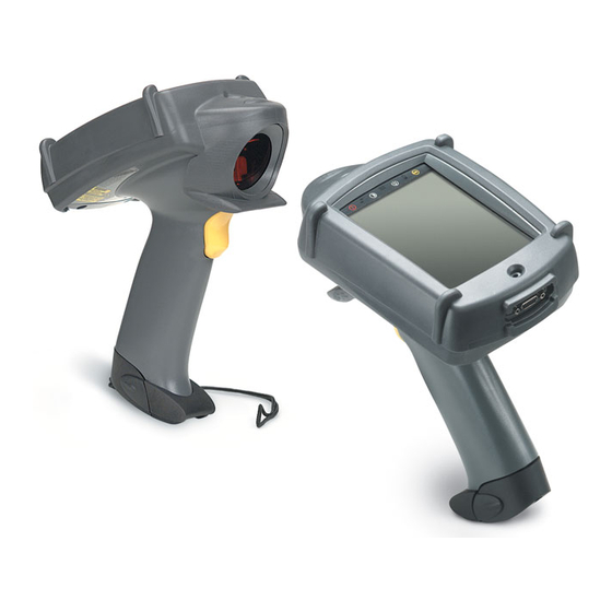
PDT 7200 Series Product Reference Guide Parts of the Terminal The following illustration displays the basic parts of the PDT 7200 terminal. A brief description of each part follows. Icons Status 1/4 VGA-sized Beeper/Speaker Display with Touchscreen Microphone Scanner Window... -
Page 22: Accessories/Peripherals
(and requires) its own international power supply with IEC connector. The cradle provides terminal storage, in-terminal battery charging, spare battery pack charging, and RS-232 communications to a Symbol Series 3000 cradle, PPT 4100 cradle, host computer, or an external serial device such as a printer. -
Page 23: Pcmcia Cards
To develop applications for Spectrum24 for the PDT 724X, you must install both the Series 7000 SDK and the Spectrum24 NDK for DOS . Third-Party Software ® Other application development environments are available, such as Zetes MCL Collection. Contact your Symbol Representative for more information. -
Page 24: Before You Use The Terminal
Getting Started Before You Use the Terminal Install and Charge Battery Prior to using the PDT 7200 for the first time, charge the Lithium-Ion battery. The battery can be charged while in the terminal or charged separately in the cradle’s charging slot. Refer to Chapter 3, Cradle Setup and Operation, for instructions on setting up the cradle... - Page 25 PDT 7200 Series Product Reference Guide...
- Page 26 Chapter 2 Software Installation on Development PC Chapter Contents Introduction ..............2-3 SDK for DOS .
- Page 27 PDT 7200 Series Product Reference Guide...
-
Page 28: Introduction
The PDT 7200 is designed to run MS DOS 6.22, and all of the programs provided by Symbol for the PDT 7200 are based on MS DOS 6.22. If you use any other version of DOS in the PDT 7200, Symbol cannot guarantee that all of the terminal’s features will function properly. -
Page 29: Spectrum24 Ndk For Dos
PDT 7200 Series Product Reference Guide Spectrum24 NDK for DOS The NDK provides the driver, utilities, sample code and documentation necessary to interface to the Spectrum24 LAN. The NDK also provides components of the Novell NetWare and LAN Workplace stacks for use with the PDT 7240. - Page 30 Software Installation on Development PC CRADLE SYMSDK\SDK70 FLASHAPI DOSSAMP LDIMAGE IRDA MOUSE MANUAL POWER PPTCHECK SCANNER SCANID PPTSET XBIOS SCANIDCB SCRIPTS XBIOS7X SCAN2D XSERIAL TERMINAL BOXDEMO BIOS 7200 DISKDRV 7500 DOS 6.22 HEXIMAGE 7200 PARTITION SETUP 7500 BIOS DISKDRV IRDA PCMCIA PARTITION TEAL...
- Page 31 PDT 7200 Series Product Reference Guide SYMSDK\SDK700 NDK7000 DOCS DOSSAMP CLIENT SCANTCP SCANUDP MDBDEMO SERVER UDPECHO TCPECHO MDBHOST SCRIPTS 7240 7540 Figure 2-2. PDT 7240 NDK Directories...
-
Page 32: Installing Other Development Software
Software Installation on Development PC Installing Other Development Software Developing applications for the PDT 7200 may require installing other development software such as application development environments (e.g., Visual C++.) on the development PC. Follow the installation instructions provided with this software. - Page 33 PDT 7200 Series Product Reference Guide...
- Page 34 Chapter 3 Cradle Setup and Operation Chapter Contents Introduction ..............3-3 Setting Up the Cradle .
- Page 35 PDT 7200 Series Product Reference Guide...
-
Page 36: Introduction
Cradle Setup and Operation Introduction The CRD 7200 single-slot cradle is used for battery charging, host communication, and terminal storage. This chapter covers setting up the cradle, using the cradle to charge the terminal’s battery and performing host communication with the cradle. Setting Up the Cradle Setting up the cradle involves connecting power to the cradle and connecting it to the host Connecting Power... -
Page 37: Connecting To A Host Computer, Printer Or Modem
PDT 7200 Series Product Reference Guide Connecting to a Host Computer, Printer or Modem 1. Plug an RS-232 serial cable into the RS-232 port located on the back of cradle. RS-232 Port Figure 3-2. RS-232 Communication Port 2. Connect the other end of the cable to the serial (COM) port of the host computer or printer. -
Page 38: Using The Cradle
Cradle Setup and Operation Using the Cradle Charging the Terminal's Battery The Li-Ion battery is automatically recharged whenever the terminal is properly inserted in the cradle. The terminal may be on or off. To insert the terminal in the cradle, engage the terminal’s scan bumper on the cradle rest, then gently rotate the terminal into the cradle. -
Page 39: Charging A Spare Battery
PDT 7200 Series Product Reference Guide Caution ° ° The temperature range for charging the battery pack is 5 C- 45 C. Do not use the cradle outside these temperatures. To remove the terminal from the charging slot, pull straight up and lift out of the cradle. -
Page 40: Host Communication
Cradle Setup and Operation Host Communication The cradle can be used to communicate with a host, printer or modem. The data is transferred via the IrDA port on the terminal to the IrDA port on the cradle, then transferred serially from the cradle to the host. Sending Data 1. - Page 41 PDT 7200 Series Product Reference Guide...
- Page 42 Chapter 4 Operating the Terminal Chapter Contents Introduction ..............4-3 Powering the PDT 7200.
- Page 43 PDT 7200 Series Product Reference Guide...
-
Page 44: Chapter 4. Operating The Terminal
Operating the Terminal Introduction This chapter describes how to perform basic tasks with a terminal that has been configured and charged. For information on configuring the terminal, see chapters 5-10. Powering the PDT 7200 Power for the PDT 7200 is provided by a Li-Ion rechargeable battery pack. Before powering on the terminal, initialize it and install a new or fully-charged battery pack. - Page 45 PDT 7200 Series Product Reference Guide • the application requests a suspend via an API call, or the application sets a wakeup. • Critical • the battery is removed or is very low. • power switch required to resume. The wake-up sources available on the PDT 7200 are listed in Table 4-1.
- Page 46 Operating the Terminal Table 4-1. PDT 7200 Wakeup Sources (Continued) Source Manual Default Timeout Default (power switch) COM ring (1) disabled disabled * Not supported at this time. Inserting a battery does NOT wake up the terminal. † For these devices to cause a wakeup, they must be “rearmed” if they were enabled when the terminal was suspended and the battery unlatched without an external power source being connected.
-
Page 47: Using The Touchscreen
Using the Touchscreen Keypad The PDT 7200 is equipped with virtual keypad capability. Symbol’s Keyboard Builder software (which runs on a PC using Windows 95) can be used to design customized keypads for multiple applications. -
Page 48: Using The Dual-Position Trigger
2. Ensure that a scanning-capable application is loaded and prepared to allow scanning. 3. Point the scanner at the bar code and pull the trigger to the handle. 4. Ensure that the scan beam crosses all bars and spaces on the symbol, as shown: Wrong Right Optimal scanning distance varies with bar code density and scanner optics, but most combinations work within 4 to 10 inches. -
Page 49: Scanning Options
Practice quickly shows what tolerances to work within. Note: Contact the Symbol Support Center if you have chronic difficulties scanning. Decoding properly printed bar codes should be quick and effortless. - Page 50 Figure 4-1. 1-D/PDF417 Scan Element Aiming and Scanning Patterns For best operation in smart raster mode, keep the scan pattern as parallel to the symbol’s rows as possible, keep the scanner as still as possible, and hold the scanner at an angle...
-
Page 51: Scanning Pdf417 Bar Codes
Make sure the terminal is programmed for a slab raster aiming pattern and smart raster mode. 1. Aim the scanner at the symbol. Try to keep the nose of the scanner parallel with the symbol’s rows. 2. Make sure the symbol you want to scan is within the scanning range; refer to the 1-D/PDF417 decode zones. - Page 52 You hear a short, high tone beep. Scan the Entire Bar Code Symbol • The larger the symbol, the farther away you should hold the scanner to permit the raster pattern to cover the symbol (but not more than 8 inches). See Appendix A, Specifications for more detail on the 1-D/PDF417 Scan Element Decode Zones.
- Page 53 Figure 4-4. Orienting Scanning Pattern On PDF417 Bar Code • If the vertical scan pattern is not high enough to cover a “tall” PDF417 symbol, move the scanner slowly down toward the bottom of the symbol, keeping the beam horizontal to the rows, and then slowly back upward toward the top (Figure 4-5).
-
Page 54: Performing Communication
Operating the Terminal Performing Communication There are a variety of host communication options available with the PDT 7200 terminal. IrDA Communication The PDT 7200 has an IrDA port on the base of the terminal’s handle which enables communication with another IrDA-compliant device. To perform IrDA communications, align the terminal with the other device via the IR communications port: 1. - Page 55 PDT 7200 Series Product Reference Guide 4-14...
- Page 56 Chapter 5 Terminal Configuration Issues Chapter Contents Configuration Options ............5-3 On-Board RAM .
- Page 57 PDT 7200 Series Product Reference Guide...
-
Page 58: Chapter 5. Terminal Configuration Issues
Terminal Configuration Issues Configuration Options The terminal’s on-board RAM and on-board flash configuration determine what software can be loaded on the terminal. On-Board RAM RAM configurations range from 8 MB to 16 MB. Following lists the RAM required to run applications on the PDT 7200. -
Page 59: Compact-Flash Disk
RAM where they execute. Compact-Flash Disk You can use a compact-flash disk to further expand your storage space. There are a variety of memory configurations available in compact-flash disks. Contact your Symbol Representative for more information. Application Size Considerations DOS applications often include an entire support infrastructure (aside from DOS and BIOS calls, and various APIs supplied by TSRs). -
Page 60: Pcmcia Card Considerations
Terminal Configuration Issues means that multiple applications carry multiple copies of such code. Some DOS development systems allow applications to share code, but that is the exception. PCMCIA Card Considerations PCMCIA cards can be used to provide additional storage space for applications and data. PCMCIA cards recommended for use on the PDT 7200 include: •... -
Page 61: Matching Software Requirements To The Hardware Available
PDT 7200 Series Product Reference Guide • SRAM cards (FAT-formatted) • FAT-formatted Native (Non-ATA) cards • ATA cards. CardSoft operation requires loading the CardSoft drivers into TPA memory, but provides more flexibility in configuring a system. CardSoft treats SRAM Cards as read/write/write- protected floppies and FAT-formatted native (non-ATA) flash cards as read-only floppies. -
Page 62: Flash Disk Or Compact-Flash, Augmented By Additional Ata Or Sram Card
Terminal Configuration Issues • Some software and data may be stored, via RAM disk, in extended RAM (>1MB). Note: Some software can load some or all of their code into EMS or XMS, which uses RAM beyond the first MB. To meet additional software and data storage needs: •... -
Page 63: Memory Requirements
PDT 7200 Series Product Reference Guide Memory Requirements Table 5-2 through Table 5-4 summarize the memory requirements for program and data storage for various configurations based on application requirements. Table 5-2. Program Storag e Application Requirements Recommended Hardware Required Configuration(s) - Page 64 Terminal Configuration Issues Table 5-2. Program Storage (Continued) Application Requirements Recommended Hardware Required Configuration(s) Very Large Program Storage Flash Disk Based, Same as A, B, or C. augmented by OS and support files will not fit Additional program storage can PCMCIA Card or within 3.8 MB of flash disk when be off-loaded to an SRAM or ATA...
- Page 65 PDT 7200 Series Product Reference Guide Table 5-3. Data Storag e Application Requirements Recommended Hardware Required Configuration(s) Very Small Data Storage, Use RAMDRIVE.SYS to 8 MB RAM Noncritical create RAM Disk Ram Disk(s) can be located (via Data storage fits within one or...
- Page 66 Terminal Configuration Issues Table 5-4. CardSoft Program/Data Storag e Application Requirements Recommended Configuration(s) Full CardSoft, Low, No EMS Load full CardSoft into conventional memory without EMS. Application requires support of SRAM and ATA cards, plus power management of cards. Use the following list of commands in CONFIG.SYS: Using additional conventional memory to hold card configuration information is preferable to...
- Page 67 PDT 7200 Series Product Reference Guide Table 5-4. CardSoft Program/Data Storage (Continued) Application Requirements Recommended Configuration(s) Full CardSoft, Low, EMS (continued) Socket Services 4 KB Card Services 43 KB ATA Support 11 KB SRAM Support 3 KB MTD Driver 10 KB...
- Page 68 Terminal Configuration Issues Table 5-4. CardSoft Program/Data Storage (Continued) Application Requirements Recommended Configuration(s) Full CardSoft, High (Best Case) No EMS Also ensure that all card library (.CLB) files (continued) for card types that will be used are loaded into the same directory and referenced as CardLib= lines in the [Libraries] section of CARDID.INI.
- Page 69 PDT 7200 Series Product Reference Guide Table 5-4. CardSoft Program/Data Storage (Continued) Application Requirements Recommended Configuration(s) Partial CardSoft, High, No EMS, Support for SRAM Only (continued) Socket Services 4 KB Card Services 43 KB SRAM Support 3 KB MTD Driver...
-
Page 70: Terminal Configuration Process
Terminal Configuration Issues Terminal Configuration Process Setting up and initializing the PDT 7200 requires performing one or more of a series of procedures listed below. • Creating the applications — refer to the Series 7000 System Software Manual (p/ n 70-36860-xx) included with the SDK for more information •... - Page 71 PDT 7200 Series Product Reference Guide 5-16...
- Page 72 Symbol-Supplied Network Configuration Files ........6-13...
- Page 73 PDT 7200 Series Product Reference Guide...
-
Page 74: Chapter 6. Terminal Configuration: Editing The Configuration Files
Terminal Configuration: Editing the Configuration Files Introduction This chapter details the edits recommended for DOS system files. For more information on ® editing these files, please refer to the Microsoft MS-DOS User’s Guide. Note: see the Spectrum24 NDK for config.sys and autoexec.bat file edits required for use in that environment. - Page 75 PDT 7200 Series Product Reference Guide Extended memory is “translated” into other types of memory such as Upper Memory Blocks (UMBs) and Expanded Memory (EMS). UMBs allow additional RAM memory to be located in unused areas of the first 1 MB of the address space. TSRs and drivers can be loaded into UMBs via the LOADHIGH and DEVICEHIGH commands, leaving additional Transient Program Area (TPA) available for application use.
- Page 76 Terminal Configuration: Editing the Configuration Files • DEVICE = driver.ext DEVICEHIGH = driver.ext Causes a device driver to be loaded either low (into TPA) or high (into UMBs). Drivers cannot be loaded high until both HIMEM.SYS and EMM386.EXE are loaded low and DOS=UMB is specified.
- Page 77 PDT 7200 Series Product Reference Guide too few files may cause an application or environment to fail if it attempts to open too many files. Unless there is a specific requirement for more files, we recommend using a value of n=20.
- Page 78 Terminal Configuration: Editing the Configuration Files required by TSRs loaded via the INSTALL= command, or if the application is being used as a command shell (e.g., turn-key application). • SET COMSPEC= Specifies the drive and path where the shell can be found. Use this command only if the SHELL= command is used to select a program other than COMMAND.COM as the shell, or if the shell is located in a directory other than the root directory of the boot drive.
- Page 79 “disks” available on the PDT 7200, this driver may be of limited use. CardSoft Device Drivers CardSoft is supplied with the Symbol Series 7000 SDK as a series of drivers that must be loaded in the terminal and activated via CONFIG.SYS.
-
Page 80: Symbol Supplied Drivers
CONFIG.SYS (instead of AUTOEXEC.BAT) with the other CardSoft files listed above using the Install= command. Do NOT load CS_APM in both CONFIG.SYS and AUTOEXEC.BAT! Symbol Supplied Drivers AUTOEXEC.BAT Note: AUTOEXEC.BAT is processed by COMMAND.COM and has no meaning if another program is used as a shell (see the section SHELL= above). -
Page 81: Symbol-Supplied Tsrs
PDT 7200 Series Product Reference Guide Symbol-Supplied TSRs Symbol has provided the following device drivers and TSRs for use with the PDT 7200. For information on loading the TSRs and device drivers, and on the APIs supported by each device driver or TSR, refer to the Series 7000 System Software Manual for DOS, p/n 70- 36860-XX. - Page 82 Note: Do NOT load CS_APM in CONFIG.SYS and AUTOEXEC.BAT. Spectrum24 ODI The Spectrum24 ODI drivers provided by Symbol consist of Novell’s Link Support Layer (LSL), Novell’s TCP/IP and Symbol’s Multiple Link Interface Driver (MLID) layers. These executables are part of the Spectrum 24 NDK for DOS.
-
Page 83: Symbol-Supplied Utilities
This utility is provided with the source code and an abstract explaining its use in the DOSSAMP\PDTCHECK directory. CardSoft is supplied with the Symbol Series 7000 SDK as a series of drivers which are loaded in CONFIG.SYS: ATADRV.EXE... -
Page 84: Symbol-Supplied Network Configuration Files
Card identification initialization file (base). Note: . CLB includes various card library files used in CARDID.INI to allow automatic recognition and configuration of PCMCIA cards. Symbol-Supplied Network Configuration Files See the Spectrum24 NDK for DOS for specific network configuration instructions. 6-13... - Page 85 PDT 7200 Series Product Reference Guide 6-14...
- Page 86 Chapter 7 Terminal Configuration: Building and Sending the Hex Image Chapter Contents Introduction ..............7-3 Starting Terminal Configuration Manager .
- Page 87 PDT 7200 Series Product Reference Guide...
-
Page 88: Chapter 7. Terminal Configuration
Terminal Configuration: Building and Sending the Hex Image Introduction Terminal Configuration Manager (TCM) is a Symbol SDK utility designed to assist you in setting up the FLASH Disk image. TCM simplifies building and downloading hex images to the terminal. In TCM, you create a script that contains the information (commands to copy files) for building the image. -
Page 89: Starting Terminal Configuration Manager
PDT 7200 Series Product Reference Guide Starting Terminal Configuration Manager To start TCM, double click on the TCM icon in the SYMSDK group. The following screen appears, displaying two directory windows; Script1 and File Explorer. Each directory window is split; the left half (or pane) of the window displays the directory tree for the current... - Page 90 Terminal Configuration: Building and Sending the Hex Image The following table lists the components of the TCM start-up screen. Table 7-1. TCM Screen Components Component Description Script Window Associated with a script file containing the information to create a Flash Disk image.
-
Page 91: Defining Script Properties
PDT 7200 Series Product Reference Guide Defining Script Properties Before a script is created, the script properties must be defined. This defines the type of terminal, type of flash type, number of disks being created, the memory configuration of each disk volume. - Page 92 Terminal Configuration: Building and Sending the Hex Image Note: The options available under the disks pull-down menu changes depending on the flash type. Some flash types only have one option for the number of disk volumes, others have two options. 6.
-
Page 93: Creating The Script For The Hex Image
Note: If you open and make changes to an existing script, saving the changes writes over the existing script. If you wish to use an original or Symbol-supplied standard script as a base and save the changes in a new script, use Save As instead of Save after making the... -
Page 94: Copy Components To The Script
Terminal Configuration: Building and Sending the Hex Image Copy Components to the Script Copy files from the File Explorer Window to the Script Window using the drag and drop method with the mouse or the Copy command. To copy files or directories to the script being generated: 1. -
Page 95: Building The Image
Note: If you open and make changes to an existing script, saving the changes writes over the existing script. If you wish to use an original or Symbol-supplied standard script as a base and save the changes in a new script, use Save As instead of Save after making the changes. - Page 96 Terminal Configuration: Building and Sending the Hex Image On the toolbar, choose . The Configure Build window appears. 3. Select whether to build the partition table, or one volume. 4. Select ASCII format for your hex image, or Compression, which reduces the size of most hex images in order to speed downloading.
-
Page 97: Sending The Hex Image
PDT 7200 Series Product Reference Guide Sending the Hex Image Once the hex file is built, you are ready to download it to the terminal. A Hex image download requires both TCM and a program loader stored on the terminal. The terminal comes with a program loading utility, Initial Program Loader (IPL), stored in the terminal’s... - Page 98 Terminal Configuration: Building and Sending the Hex Image On the toolbar, choose . The Load Terminal screen displays. 3. If the correct hex file is not displayed in the Hex File to field, click on the browse button and navigate to the correct hex file to be downloaded. 4.
-
Page 99: Initial Program Loader (Ipl)
Hex files for standard system components such as the BIOS and Setup are provided by Symbol. Hex files for custom components, such as disk images or custom partition maps are built on a PC using the TCM program. IPL is only capable of loading whole partitions (it cannot update individual files in a disk image). -
Page 100: Using The Touch Screen
Terminal Configuration: Building and Sending the Hex Image Using the Touch Screen If the system supports a touch screen, then the touch screen can be used instead of the keyboard to control IPL. Cursor Up/Down Touching the screen on the up or down arrows on the screen is exactly the same as using the Cursor Up/Down keys on the keyboard. - Page 101 PDT 7200 Series Product Reference Guide The terminal displays the copyright screen for three seconds. During this time, IPL is verifying the Partition Map and the mandatory and checksummed partitions. Elan IPLVer. 1.0 Copyright 95-99 Symbol Tech. Flash Type 0810a The version number on the top of the screen identifies the version of IPL you are using.
- Page 102 Terminal Configuration: Building and Sending the Hex Image Icon for 16 seconds. Both methods have the same effect, but selecting “Run System” is faster. Once the selection is made, IPL proceeds to the Area Selection Menu. IPL Ver 1.0 Prev. Menu Single Image Multiple Images BIOS...
- Page 103 PDT 7200 Series Product Reference Guide 4. After selecting the area, press Enter. IPL checks for the presence of external power. If the system is running off battery power, IPL displays the Connect to Power Screen: Insert in Cradle Connect Power Supply 5.
- Page 104 Terminal Configuration: Building and Sending the Hex Image The top line of this screen identifies the area selected in the Area Selection screen. Once a character has been received, IPL stays in this screen until an entire image has been received, or until an error is detected.
-
Page 105: Ipl Error Detection
PDT 7200 Series Product Reference Guide If the Multiple Images option was selected on the Area Selection screen, IPL then immediately returns to the Waiting for Data screen to wait for the next image. If any other selection was made on the Area Selection screen, then IPL stays at the success screen until the operator acknowledges the message by pressing Enter (or the trigger, or taps Enter on the touchscreen). - Page 106 Not Hex File This error is caused by transmitting the wrong file format to IPL. IPL can only receive Hex files supplied by Symbol, or generated by TCM. Write Error This error is caused by a failure of the flash device used to hold the image.
-
Page 107: Restarting After Download Fails
PDT 7200 Series Product Reference Guide Table 7-2. IPL Errors Error Explanation Verify Failed: This error is caused when the image has been written to flash, but cannot be read back correctly. It only applies to critical sections of the flash, and will prevent an exit from IPL as a critical section of the flash is damaged. -
Page 108: Exiting Tcm
Terminal Configuration: Building and Sending the Hex Image Exiting TCM To exit TCM on the development PC: Choose Exit from the File Menu. Press Alt+F4. Double-click the close box. 7-23... - Page 109 PDT 7200 Series Product Reference Guide 7-24...
-
Page 110: Chapter 8. Terminal Configuration: Load A Ram Disk
Chapter 8 Terminal Configuration: Load a RAM Disk Chapter Contents Loading a RAM Disk ............8-3 Standard RAM Disk Driver . - Page 111 PDT 7200 Series Product Reference Guide...
-
Page 112: Loading A Ram Disk
Terminal Configuration: Load a RAM Disk Loading a RAM Disk RAM disks allow the PDT 7200’s RAM to be organized as a simulated disk for writable data storage. To create one or more RAM disks, you can use RAMDRIVE.SYS (supplied as part of DOS). - Page 113 PDT 7200 Series Product Reference Guide...
- Page 114 Chapter 9 Terminal Configuration: Setup Chapter Contents Introduction ..............9-3 Invoking Setup .
- Page 115 PDT 7200 Series Product Reference Guide...
-
Page 116: Chapter 9. Terminal Configuration: Setup
Terminal Configuration: Setup Introduction The PDT 7200 Series terminal has a system setup program that allows you to configure many of the terminal’s basic characteristics. Specifically, the setup program is made up of five screens and defines: • contrast value •... -
Page 117: Invoking Setup
While the terminal is booting, a message displays on the bottom of the screen, “Hold Trig for Setup”. 2. Press and hold the scan trigger button, until the setup application starts. The Symbol PDT 7200 Setup screen displays, providing the menu of setup options for selection. Figure 9-1. PDT 7200 Setup Screen... - Page 118 Terminal Configuration: Setup factory defaults. To cancel the reset and return to the Main Setup screen, tap the CANCEL option. To confirm the resetting of default values, tap the RESET DEFAULTS option. Figure 9-2. Set Defaults Screen...
-
Page 119: Main Setup
PDT 7200 Series Product Reference Guide Main Setup Selecting the Main Setup option on the PDT 7200 Setup screen displays the Main Setup screen. Figure 9-3. Main Setup Screen This screen allows you to set the system clock for the terminal, and set the desired screen contrast, backlight, and beeper volume. -
Page 120: Advanced
Terminal Configuration: Setup Advanced Selecting the Advanced option on the PDT 7200 Setup Screen displays the Advanced Setup screen. Figure 9-4. Advanced Setup Screen This screen allows you to set the reset time, which is the period of time in seconds that the power icon must be pressed to cold boot the terminal;... -
Page 121: Power
PDT 7200 Series Product Reference Guide compact flash is drive C: and the on-board flash drives are drives D: and upwards. If compact flash is selected and fixed/removable is selected, then the first on-board flash is drive C:, the compact flash is drive D: and the remaining on-board flash disks are drive E: and upwards. - Page 122 Terminal Configuration: Setup • Highspeed Time: defines how long the CPU stays at 66 MHz when the system does not detect any activity before dropping to 33 MHz. The following table illustrates the times associated with each value. Timer Value Time at 66 MHz (in second) Does not drop to 33 MHz 0.125...
-
Page 123: Information
PDT 7200 Series Product Reference Guide Information Selecting the Information option on the PDT 7200 Setup screen displays the System Information screen. Figure 9-6. System Information Screen This screen is a read-only screen which displays: • Machine Name: displays the terminal name •... -
Page 124: Password
Terminal Configuration: Setup Password Selecting the Password option on the PDT 7200 Setup screen displays the Password Setup screen. Figure 9-7. Password Setup Screen To select a numeric password for your terminal, tap the desired numbers. As they are selected, they display in the Password field. Tap clear to clear the data from the password field. -
Page 125: Exit
PDT 7200 Series Product Reference Guide Exit Selecting the Exit option from the PDT 7200 Setup screen displays the Exit Confirmation screen. Figure 9-8. Exit Confirmation Screen This screen allows you to determine how you want to exit the setup. To cancel the exit request, tap CANCEL. - Page 126 Chapter 10 Terminal Configuration: Setting Up PCMCIA Cards Chapter Contents PCMCIA Cards ............. . 10-3 Formatting PCMCIA Cards .
- Page 127 PDT 7200 Series Product Reference Guide 10-2...
-
Page 128: Pcmcia Cards
Terminal Configuration: Setting Up PCMCIA Cards PCMCIA Cards PCMCIA cards supplement the terminal’s on-board flash or RAM, and provide additional I/O devices. There are many options regarding the type of card and format to use. For a discussion of PCMCIA card options, refer to Chapter 5, Terminal Configuration Issues. -
Page 129: Using Drvspace To Extend Storage On Pcmcia Card
PDT 7200 Series Product Reference Guide Using DRVSPACE to Extend Storage on PCMCIA Card DRVSPACE can be used to extend storage on PCMCIA cards in the same way it is used to extend storage on a standard PC drive. The process is as follows: 1. - Page 130 Chapter 11 Troubleshooting and Maintenance Chapter Contents Cleaning the Terminal ............11-3 Storage .
- Page 131 PDT 7200 Series Product Reference Guide 11-2...
-
Page 132: Cleaning The Terminal
Troubleshooting and Maintenance Cleaning the Terminal The PDT 7200 requires a minimal amount of maintenance. To prolong its life and avoid problems, keep the terminal clean. Use a clean, soft cloth dampened with a mild cleanser such as soap and water to clean the terminal. Do NOT use abrasive paper/cloth or abrasive/corrosive cleaners. -
Page 133: Troubleshooting
PDT 7200 Series Product Reference Guide Troubleshooting Terminal Problems Table 11-1 covers some common terminal problems and what actions to take. Table 11-1. Terminal Problems Symptom Possible Cause Action Terminal does not power up Battery not installed or fully Verify that the battery is charged. -
Page 134: Cradle Problems
Troubleshooting and Maintenance Table 11-1. Terminal Problems (Continued) Symptom Possible Cause Action Battery life is inadequate Battery is not fully charged. Charge the battery, either in the terminal or separately for a full 2 hours. Battery is old. Replace with a fresh, fully charged battery. - Page 135 PDT 7200 Series Product Reference Guide Table 11-2. Cradle Troubleshooting (Continued) Symptom Probable Cause Action Rechargeable battery in Battery failed. Replace battery. terminal or spare battery did Terminal or battery was Replace terminal and/or spare not charge removed from cradle too soon battery in cradle and begin charging over.
-
Page 136: Environment
Appendix A Specifications Environment The PDT 7200 is designed to operate in harsh environments. Table A-1 below summarizes the PDT 7200’s intended operating environment. Table A-1. PDT 7200 Operating Environment Operating Temperature -20° C to 50° C (-4° F to 122° F) Humidity 0% to 95% non-condensing Shipping and Storage... -
Page 137: Decode Zones
PDT 7200 Series Product Reference Guide Decode Zones Standard Range NOTE: Typical performance at 68 F ( 20 C) on high quality symbols. 11.7 29.75 Integrated 12.7 Scanner 005 In. 12.7 Depth of 0075 In. Field in Inches 020 In. Minimum Element Width 11.7... - Page 138 Specifications SE 2000 1-D Decode Zone NOTE: Typical performance at 68 F ( 20 C) on high quality symbols. Y-module dimension = 3 X. 25.4 12.7 Integrated Scanner 006 In. 12.7 Depth of 0075 In. Field in Inches 020 In. Min. Element Width 25.4 040 In.
-
Page 139: Pdt 7200 Memory Map
PDT 7200 Series Product Reference Guide PDT 7200 Memory Map FFFF:000FH (1 meg) BIOS + Flash API + Pen API E000:0000H Free RAM C000:0000H VIDEO RAM B800:0000H RESERVED B000:0000H FREE RAM A400:0000 PC CARD (IF USED) A000:0000H COMMAND.COM (TPA) FREE RAM COMMAND.COM... - Page 140 Specifications Table A-2. PDT 7200 Interrupt Definitions DOS IRQ Win CE Interrupt Interrupt Notes/Comments Name IRQ Name Source Description Interrupt ID Name Interrupt ID# INTR_TIMER0 Internal to Timer Tick Standard PC Timer SYSINTR_RESCHEDULE Elan Interrupt Tick (Internal Timer) INTR_KEYBOARD Internal to AT Keyboard Emulated by SCP SYSINTR_KEYBOARD...
- Page 141 PDT 7200 Series Product Reference Guide Table A-2. PDT 7200 Interrupt Definitions (Continued) DOS IRQ Win CE Interrupt Interrupt Notes/Comments Name IRQ Name Source Description Interrupt ID Name Interrupt ID# INTR_PERIPH_MULITPLEX Elan PIRQ4 Multiplex B in Peripheral Multiplex ASIC Interrupt...
- Page 142 Specifications Table A-2. PDT 7200 Interrupt Definitions (Continued) DOS IRQ Win CE Interrupt Interrupt Notes/Comments Name IRQ Name Source Description Interrupt ID Name Interrupt ID# INTR_PCMCIA_B_DATA Internal to PC Card 2 Used by PCMCIA SYSINTR_PCMCIA_LEVEL Elan Interrupt card client driver. (PCMCIA Controller) INTR_RTC...
- Page 143 PDT 7200 Series Product Reference Guide Table A-2. PDT 7200 Interrupt Definitions (Continued) DOS IRQ Win CE Interrupt Interrupt Notes/Comments Name IRQ Name Source Description Interrupt ID Name Interrupt ID# SYSINTR_PROFILE Internal to Precision Medium resolution ASIC (1 ms Timer...
- Page 144 Specifications Table A-2. PDT 7200 Interrupt Definitions (Continued) DOS IRQ Win CE Interrupt Interrupt Notes/Comments Name IRQ Name Source Description Interrupt ID Name Interrupt ID# SYSINTR_SCANNER_SOS Internal to SOS Interrupt Non-decoded ASIC (ASIC scanner DBP data QSNAC) ready SYSINTR_SCANNER_ZIF ASIC Input ZIF Interrupt Single or dual stage trigger status change.
- Page 145 PDT 7200 Series Product Reference Guide Table A-2. PDT 7200 Interrupt Definitions (Continued) DOS IRQ Win CE Interrupt Interrupt Notes/Comments Name IRQ Name Source Description Interrupt ID Name Interrupt ID# Elan XMI from GPIO_CS0 ASIC Soft XMI Software generated Multiplex...
- Page 146 Specifications Table A-2. PDT 7200 Interrupt Definitions (Continued) DOS IRQ Win CE Interrupt Interrupt Notes/Comments Name IRQ Name Source Description Interrupt ID Name Interrupt ID# Wake Up Elan WAKEUP Suspres Pin multiplex from ASIC SUSPRES WAKE UP COM1 Ring Wakeup from RI Multiplex signal change on ASIC internal UART1...
- Page 147 PDT 7200 Series Product Reference Guide Table A-2. PDT 7200 Interrupt Definitions (Continued) DOS IRQ Win CE Interrupt Interrupt Notes/Comments Name IRQ Name Source Description Interrupt ID Name Interrupt ID# Right Trigger Wakeup from signal change on ASIC external Trigger 0 or...
- Page 148 Specifications Table A-2. PDT 7200 Interrupt Definitions (Continued) DOS IRQ Win CE Interrupt Interrupt Notes/Comments Name IRQ Name Source Description Interrupt ID Name Interrupt ID# COM1 RXD Wakeup from mark- to-space transition on RXD signal on ASIC internal UART1 COM2 RXD Reserved for wakeup from mark-to-space transition on RXD...
- Page 149 PDT 7200 Series Product Reference Guide A-14...
- Page 150 Index Numerics performing communications ..4-13 troubleshooting problems ..11-5 1-D bar code ......4-8 2-D bar codes .
- Page 151 PDT 7200 Series Product Reference Guide front view ......1-4 PCMCIA cards ....5-3 segments .
- Page 152 ....11-5 symbol support center ....xi terminal fails to power up .
- Page 153 PDT 7200 Series Product Reference Guide Index-4...
- Page 154 We’d like to know what you think about this Manual. Please take a moment to fill out this questionnaire and fax this form to: (631) 738-3318, or mail Symbol Technologies, Inc. One Symbol Plaza M/S B-4 Holtsville, NY 11742-1300 Attn: Technical Publications Manager IMPORTANT: If you need product support, please call the appropriate cus- tomer support number provided.
- Page 155 PDT 7200 Series Product Reference Guide for DOS 72-39656-02 Revision A — March 2001 Symbol Technologies, Inc. One Symbol Plaza, Holtsville N.Y. 11742-1300...