Table of Contents
Advertisement
Quick Links
Advertisement
Chapters
Table of Contents

Related Manuals for HYOSUNG Prima


Summary of Contents for HYOSUNG Prima
- Page 1 HYOSUNG MOTORS & MACHINERY INC. SERVICE MANUAL 99000-91310...
-
Page 2: Table Of Contents
GROUP INDEX FOREWORD This manual contains an introductory description on GENERAL INFORMATION HYOSUNG PRIMA(SF-50) and procedures for its inspec- tion/service and overhaul of its main components. Other information considered as generally known is not included. PERIODIC MAINTENANCE Read GENERAL INFORMATION section to familiarize... -
Page 3: How To Use This Manual
HOW TO USE THIS MANUAL TO LOCATE WHAT YOU ARE LOOKING FOR: 1. The text of this manual is divided into sections. 2. As the title of these sections are listed on the previous page as GROUP INDEX, select the section where what you are looking for belong. - Page 4 SYMBOL Listed in the table below are the symbols indicating instructions and other information necessary for servicing and meaning associated with them respectively. SYMBOL DEFINITION SYMBOL DEFINITION Torque control required. Apply THREAD LOCK “1324” . Data beside it indicates specified torque. Apply oil.
- Page 6 GENERAL INFORMATION CONTENTS 1 - 1 INFORMATION LABELS 1 - 1 GENERAL PRECAUTIONS 1 - 3 SERIAL NUMBER LOCATION 1 - 3 FUEL AND OIL RECOMMENDATIONS 1 - 4 BREAK-IN PROCEDURES EXTERIOR ILLUSTRATION 1 - 5 SPECIFICATIONS 1 - 6...
-
Page 7: General Precautions
1-1 GENERAL INFORMATION WARNING / CAUTION / NOTE Please read this manual and follow its instructions carefully. To emphasize special information, the symbol and the words WARNING, CAUTION and NOTE have special meanings. Pay special attention to the messages highlighted by these signal words. WARNING Indicates a potential hazard that could result in death or injury. - Page 8 GENERAL INFORMATION 1-2 CAUTION ● If parts replacement is necessary, replace the parts with HYOSUNG Genuine Parts or their equivalent. ● When removing parts that are to be reused, keep them arranged in an orderly manner so that they may be reinstalled in the proper order and orientation.
-
Page 9: Serial Number Location
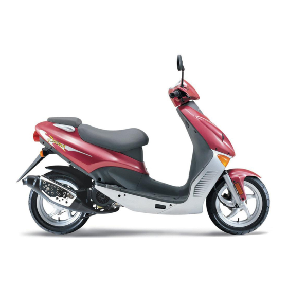
1-3 GENERAL INFORMATION HYOSUNG PRIMA (SF - 50) RIGHT SIDE LEFT SIDE * Difference between photographs and actual motorcycles depends on the markets. SERIAL NUMBER LOCATION The frame serial number or V.I.N. (Vehicle Identification Number) is stamped on the right side of the frame under the footboard. -
Page 10: Break-In Procedures
GENERAL INFORMATION 1-4 ENGINE OIL Specification and classification: APOLLOIL BIKE-K, HYPOL HS BRAKE FLUID Specification and classification: DOT4 WARNING Since the brake system of this motorcycle is filled with a glycol-based brake fluid by the manufacturer, do not use or mix different types of fluid such as silicone-based and petroleum-based fluid for refilling the sys- tem, otherwise serious damage will result. -
Page 11: Exterior Illustration
1-5 GENERAL INFORMATION EXTERIOR ILLUSTRATION 1,270 1,825 Rear reflector Head lamp Tail/Brake lamp ( Rear ) Turnsignal ( Front ) Turnsignal lamp lamp... -
Page 12: Specifications
GENERAL INFORMATION 1-6 SPECIFICATIONS DIMENSIONS AND DRY MASS Overall length 1,825 mm (71.9 in) Overall width 635 mm (25.0 in) Overall height 1,110 mm (43.7 in) Wheelbase 1,270 mm (50.0 in) Ground clearance 125 mm (4.9 in) Dry mass 88 kg (194 lbs) ENGINE Type Two-stroke, forced air cooled... - Page 13 1-7 GENERAL INFORMATION ELECTRICAL Ignition type “CDI”type Ignition timing 20。 B.T.D.C. at 1,000 rpm Spark plug BR8HSA Battery 12V 3Ah/10HR Generator Magneto Fuse Headlamp 15W×2 Turn signal lamp 10W×4 Tail/Brake lamp 5/10W Speedometer lamp 1.7W×2 Oil level indicator lamp 1.7W Turn signal indicator lamp 1.7W CAPACITIES...
- Page 14 PERIODIC MAINTENANCE CONTENTS 2 - 1 PERIODIC MAINTENANCE SCHEDULE 2 - 3 MAINTENANCE PROCEDURES 2 - 3 BATTERY 2 - 4 CYLINDER HEAD NUTS AND EXHAUST PIPE NUTS 2 - 4 CYLINDER HEAD AND CYLINDER SPARK PLUG 2 - 4 FUEL LINE 2 - 5 2 - 5...
-
Page 15: Periodic Maintenance Schedule
2-1 PERIODIC MAINTENANCE PERIODIC MAINTENANCE SCHEDULE The chart below lists the recommended intervals for all the required periodic service work necessary to keep the motorcycle operating at peak performance and economy. NOTE: More frequent servicing should be performed on motorcycles that are used under severe conditions. PERIODIC MAINTENANCE CHART ENGINE Interval... -
Page 16: Lubrication Chart
PERIODIC MAINTENANCE 2-2 LUBRICATION CHART The maintenance schedule, which follows, is based on this philosophy. It is timed by odometer indication, and is calculated to achieve the ultimate goal of motorcycle maintenance in the most economical manner. Interval Initial and Every 4,000 km Every 8,000 km Item Throttle cable... -
Page 17: Maintenance Procedures
2-3 MAINTENANCE PROCEDURE MAINTENANCE PROCEDURE This section describes the service procedures for each section of the periodic maintenance. BATTERY NOTE: Inspect Initial 1,000 km and Every 4,000 km. ● Remove the pillion seat for measure of battery voltage. ● Remove the battery � lead and then � lead at the battery terminls and remove the battery. -
Page 18: Engine
MAINTENANCE PROCEDURE 2-4 CYLINDER HEAD NUTS AND EXHAUST PIPE NUTS NOTE: Inspect Initial 1,000 km and Every 4,000 km. ① CYLINDER HEAD NUTS ● Remove the personal trunk. ● Remove the spark plug cap. ● Remove the cylinder head cover bolt. (Refer to page 3 - 5) ●... -
Page 19: Fuel Line
2-5 MAINTENANCE PROCEDURE ● If the center electrode is fairly worn down, the plug should be replaced and the plug gap set to the speci- fied gap using a thickness gauge. Thickness gauge : 09900 - 20804 Spark plug gap 0.6 ~ 0.7 mm ●... -
Page 20: Throttle Cable Play
● Immerse the element in Hyosung genuine oil, and squeeze the oil out of the element leaving it slightly wet with oil. -
Page 21: Engine Idle Speed
2-7 MAINTENANCE PROCEDURE ENGINE IDLE SPEED NOTE: Inspect Initial 1,000 km and Every 4,000 km. CAUTION Make this adjustment when the engine is hot. ① ● start up the engine and set its speed at anywhere between 1,750 and 1,850 rpm by turning the throttle stop screw ①... -
Page 22: Transmission Oil
Specification and classification DOT4 WARNING HYOSUNG Brake fluid : 99000 - 23021 Brake fluid, if it leaks, will interfere with safe run- WARNING ning and immediately discolor painted surfaces. Check the brake hoses for cracks and hose joints The brake system of this motorcycle is filled with for leakage before riding. - Page 23 2-9 MAINTENANCE PROCEDURE BRAKE PADS Wearing condition of brake pads can be checked by observing the limit line ① marked on the pad. When the wear exceeds the limit mark, replace the pads with new ones. BRAKE LAMP SWITCH For the brake lamp come on after the brake lever is pulled, adjust the brake lamp switch.
-
Page 24: Tires
MAINTENANCE PROCEDURE 2-10 WARNING Handle the brake fluid with care: the fluid reacts � chemically with paint, plastics, rubber materials, etc. REAR BRAKE Adjust by turning the adjusting nut ① so that the play � 사용범위 사용범위 사용범위 사용범위 사용범위 사용범위... -
Page 25: Steering
110/70 - 12 47J for front and 120/70 - 12 51J for rear. The use of a tire other than the standard may cause handling instability. It is highly recom- mended to use a HYOSUNG Genuine Tire. NORMAL RIDING COLD INFLATION... -
Page 26: Rear Suspension
MAINTENANCE PROCEDURE 2-12 REAR SUSPENSION NOTE: Inspect Initial 1,000 km and Every 8,000 km. Inspect the rear shock absorber for oil leak and the mounting rubbers including engine mountings for wear and damage. Replace the defective part if necessary. CHASSIS AND ENGINE MOUNTING BOLTS AND NUTS NOTE: Inspect Initial 1,000 km and Every 4,000 km. - Page 27 2-13 MAINTENANCE PROCEDURE ⑩ ③ ④ ⑪ ⑥ ⑤ ⑦ ⑧ ⑫ ⑬ ⑨...
- Page 28 ENGINE CONTENTS 3 - 1 ENGINE REMOVAL AND REMOUNTING 3 - 1 ENGINE REMOVAL 3 - 3 ENGINE REMOUNTING 3 - 4 ENGINE DISASSEMBLY 3 - 14 ENGINE COMPONENTS INSPECTION AND SERVICING 3 - 14 BEARINGS 3 - 14 OIL SEALS 3 - 15 CRANKSHAFT 3 - 15...
-
Page 29: Engine Removal And Remounting
3-1 ENGINE ENGINE REMOVAL AND REMOUNTING ENGINE REMOVAL ② Before taking the engine out of the frame, thoroughly clean the engine with a suitable cleaner. The procedure of engine removal is sequentially explained as follows. ● Remove the low leg shield. ●... - Page 30 ENGINE 3-2 ● Disconnect the magneto lead wire � and starting moter lead wire � . � � ● Remove the rear brake cable ④ by removing the bolt ① , bolt ② and adjuster nut ③ . ① ② ④...
-
Page 31: Engine Remounting
3-3 ENGINE ● Remove the engine mounting shaft and remove the engine from the frame. ENGINE REMOUNTING The engine can be mounted in the reverse order of removal. Front side ● Install the damper to the crankcase bracket as shown ①... -
Page 32: Engine Disassembly
ENGINE 3-4 ● Install the magneto lead wire � and starting motor lead wire � correctly. � � After remounting the engine, route the wiring harness properly and following adjustments are necessary. Page 2 - 6 ∙Throttle cable play 2 - 7 ∙Idling adjustment 2 - 7 ∙Oil pump cable paly... - Page 33 3-5 ENGINE ● Remove the magneto rotor with the special tool. Rotor remover : 09930 - 30163 Rotor remover sliding shaft : 09930 - 30102 ● Remove the magneto stator and key. REED VALVE ● Remove the intake pipe ② with reed valve ① . ②...
- Page 34 ENGINE 3-6 PISTON ● Place a cloth beneath the piston and remove the pis- ton circlip ① with a long nose pliers. ● Remove the piston pin ② and piston ③ . ③ ● Remove the piston pin bearing ④ . ②...
- Page 35 3-7 ENGINE MOVABLE DRIVE FACE ● Remove the kick starter driven nut ① with the special tool. CAUTION This nut has left-hand thread. Conrod holder : 09910 - 20115 ● Remove the fixed drive face ② and V - belt ③ . ●...
- Page 36 ENGINE 3-8 ● Loosen the clutch shoe nut with the special tool. Rotor holder : 09930 - 40113 ● Remove the nut while holding down the clutch shoe assembly ② by both hands as shown in the illustration. WARNING Gradually back off the clutch shoe assembly pressed down by hand to counter the clutch spring load.
- Page 37 3-9 ENGINE ● Remove the roller bearing � with the special tools. Bearing remover( ф 17 mm) : 09923 - 73210 � Rotor remover sliding shaft : 09930 - 30102 CAUTION The removed bearing should be replaced with a new one. ●...
- Page 38 ENGINE 3-10 ● Remove the oil seal ① from the gear box cover with the special tool. Oil seal remover : 09913 - 50121 ① CAUTION The removed oil seal should be replaced with a new one. ● Remove the bearing ② with the special tool. Bearing installer : 09913 - 76010 CAUTION ②...
- Page 39 3-11 ENGINE WHEEL, BRAKE ● Remove the rear axle nut ① and washer ② . ● Remove the rear wheel ③ . ② ① ③ ● Remove the brake shoes ④ and rear axle shaft ⑤ . ④ ⑤ ④ ●...
- Page 40 ENGINE 3-12 ● Remove the oil seal ① with the special tool. Oil seal remover : 09913 - 50121 ① CENTER STAND ● Remove the return spring ② . ② ● Remove the cotter pin ③ , washer ④ and shaft ⑤ . ⑤...
- Page 41 3-13 ENGINE ● Remove the crankshaft with the special tool. Crankcase separater : 09920 - 13120 ● Remove the bearings, oil seals and bushings.
-
Page 42: Engine Components Inspection And Servicing
ENGINE 3-14 ● Using two steel tubes of appropriate size, press out the engine mounting bushings on a vise as shown in Bushing the illustration. Front side Rear side Bushing Bushing Crankcase Crankcase ENGINE COMPONENTS INSPECTION AND SERVICING BEARINGS Wash the bearing with cleaning solvent and lubricate with motor oil before inspecting. -
Page 43: Crankshaft
3-15 ENGINE CRANKSHAFT CRANKSHAFT RUNOUT Support crankshaft by “ V ” blocks, with the dial gauge rigged to read the runout as shown. Crankshaft runout Service limit 0.08 mm Excessive crankshaft runout is often responsible for abnormal engine vibration. Such vibration shortens engine life. - Page 44 ENGINE 3-16 1. CLUTCH-IN INSPECTION Warm up the motorcycle to normal operating tempera- ture. Remove the right frame side cover. Connect an engine tachometer to the engine. Seated on the motorcycle with the motorcycle on level ground, increase the engine RPMs slowly and note the RPM at which the motorcycle begins to move forward.
- Page 45 3-17 ENGINE CAUTION Clutch shoes or springs must be changed as a set and never individually. Clutch housing - inspect visually the condition of the inner clutch housing surface for scrolling, cracks, or uneven wear. Measure inside diameter of the clutch wheel with inside calipers.
-
Page 46: Cylinder Head
ENGINE 3-18 MOVABLE DRIVEN SPRING Measure the free length of the movable driven spring. If the length is shorter than the service limit, replace the spring with a new one. Movable driven spring free length Service limit 135~153 mm MOVABLE DRIVEN FACE PIN AND OIL SEAL Turn the movable driven faces and check to see that the movable driven faces turn smoothly. -
Page 47: Cylinder
3-19 ENGINE If the largest reading at any portion of the straightedge exceeds the limit, rework the surface by rubbing it against emery paper (of about # 400) laid flat on the sur- face plate in a lapping manner. The gasketed surface must be smooth and perfectly flat in order to secure a tight joint: a leaky joint can be the cause of reduced power output and increased fuel consumption. - Page 48 ENGINE 3-20 As a result of the above measurement, if the piston-to- cylinder clearance exceeds the following limit, overhaul the cylinder and use an oversize piston, or replace both cylinder and piston. The measurement for the bore diameter should be taken in the intake-to-exhaust port direction and at 20mm from the cylinder top surface.
- Page 49 3-21 ENGINE PISTON PIN O.D. Using a micrometer, measure the piston outside diame- ter at three positions. Micrometer(0~25 mm) : 09900 - 20201 Piston pin O.D. Service limit 9.980 mm PISTON RINGS Check each ring for end gap, reading the gap with a thickness gauge shown in the illustration.
-
Page 50: Reed Valve
ENGINE 3-22 REED VALVE When reinstalling the reed valve and stopper plate to the body, align the both cut on the reed valve and stop- per plate. Apply THREAD LOCK “ 1324 ” to the stopper plate securing screws. Thread Lock “ 1324 ” ENGINE REASSEMBLY Reassembly is generally performed in the reverse order of disassembly, but there are a number of reassembling... -
Page 51: Bearings
3-23 ENGINE BEARINGS Install new bearings with the special tool. Bearing installer : 09913 - 75810 Bearing installer : 09913 - 76010 BUSHINGS ② Using two steel tubes of appropriate size and a vise, press the mounting bushings ① and ② into the crankcase holes as shown in the illustration. -
Page 52: Crankshaft
ENGINE 3-24 ② Bushing Bushing ① Crankcase Crankcase � CRANKSHAFT ① Crank shaft ② Crankcase RH ③ Oil seal ④ Oil seal ⑤ Oil pump drive gear ⑥ Oil pump driven gear ⑦ Oil seal ② ⑥ ③ ⑤ ⑦ ④... -
Page 53: Crankcase
3-25 ENGINE ● When mounting the crankshaft into the crankcase, it is necessary to pull its left end into the crankcase with the special tool. Crankshaft installer : 09910 - 32812 Conrod holder : 09910 - 20116 CAUTION Never fit the crankshaft into the crankcase by driving it with a plastic hammer. -
Page 54: Center Stand
ENGINE 3-26 CENTER STAND ● Install the center stand ① . ④ ③ ● Install the shaft ② , washer ③ and cotter pin ④ . ① ⑤ ② ● Hook the center stand spring ⑤ into the crankcase. ⑤... -
Page 55: Rear Axle Shaft, Brake And Wheel
3-27 ENGINE REAR AXLE SHAFT, BRAKE AND WHEEL ● Install the rear axle shaft ① into the crankcase by tapping its end lightly. ① ● Apply engine oil on the left end of the rear axle shaft being inserted later in the reduction rear box cover. ●... - Page 56 ENGINE 3-28 ● When installing the cam lever ① to the cam, align the punched mark with the slit of cam lever. Punch mark Slit ① ● Tighten the cam lever nut ② to the specified torque. Rear brake cam lever nut : 6~9 N∙m (0.6~0.9 kg∙m) ②...
-
Page 57: Transmission
3-29 ENGINE TRANSMISSION ● Install the circlip ① on to the rear axle shaft ② . ● Assemble the idle shaft subassembly using the idle shaft ③ and thrust washer ④ , then install the sub- assembly on the gear box. ②... - Page 58 ENGINE 3-30 ● Install the new bearing ① , ③ to the gear box cover ② with the special tool. Bearing installer : 09913 - 76010 ③ ① ② ● Apply SUPER GREASE “ A ” to the lip of the oil seal ④...
-
Page 59: Starter Driven Gear And Starting Motor
3-31 ENGINE ● Apply BOND “ 1215 ” at the hatched area shown in the illustration and install the gear box cover ① on the crankcase. BOND “ 1215 ” ● Tighten all the screws evenly one by one in a diago- nal fashion. -
Page 60: Movable Driven And Clutch
ENGINE 3-32 ● Install the starting motor ① . ① MOVABLE DRIVEN AND CLUTCH... - Page 61 3-33 ENGINE ● Install the bearing ② in the fixed driven face ① with the special tool. Bearing installer : 09943 - 88211 CAUTION ② Take care that hit inner race of the bearing. (Fall to ring in the bearing a case.) ①...
- Page 62 ENGINE 3-34 ● Install the movable driven face ① to the fixed driven face ② . CAUTION Insert as guide the rim. When reinstalling the movable dirven face to the ① fixed dirven face, make sure that the oil seal is positioned properly.
- Page 63 3-35 ENGINE ● Tighten the clutch shoe nut to the specified torque with the special tool. Rotor holder : 09930 - 40113 Clutch shoe nut : 40~60 N∙m (4.0~6.0 kg∙m) ● Insert the V-belt between the driven faces as deep inside as possible while pulling the movable driven face all the way outside to provide the maximum belt clearance.
-
Page 64: Movable Drive
ENGINE 3-36 MOVABLE DRIVE ● Install the roller ② to the movable drive face ① . ① ② ● Mount the three dampers ④ on the movable drive plate ③ and install it on the movable drive face ⑤ . ③... - Page 65 3-37 ENGINE ● Install the movable drive face cover ① . CAUTION ① Make sure that the movable drive plate is fully ② positioned inside, or the weight roller may come off. ● Insert the spacer ② . ● Position the movable drive face subassembly on the crankshaft as shown in the photo.
-
Page 66: Kick Starter
ENGINE 3-38 ● Install the E-ring � . � � � � ● Continue turning the fixed drive face ① by hand until ② the belt is seated in and both the drive and driven faces ② will move together smoothly without slip. ●... - Page 67 3-39 ENGINE ● Apply SUPER GREASE “ A ” lightly on the kick starter shaft rolling surface and install it on the ① crankcase cover. Super Grease “ A ” ● Position the kick starter shaft return spring and hook the spring end on the crankcase cover boss ①...
-
Page 68: Piston
ENGINE 3-40 PISTON ● Install the piston rings on the piston. Position the ring so that the marking is on upside. ∙1st - Keystone ring ∙2nd - Barrel face ring � Expander ring CAUTION Position the ring so that the marking is on upside. Locating pin ●... - Page 69 3-41 ENGINE ● Apply engine oil on the piston pin and install the pis- ton to the conrod. CAUTION The arrow mark � on the piston head should � point the exhaust side. ● The circlip should be mounted in such a position that the mating ends of the circlip do not coincide with the groove portion of the piston.
-
Page 70: Oil Pump And Intake Pipe
ENGINE 3-42 OIL PUMP AND INTAKE PIPE ● Apply SUPER GREASE “ A ” to the oil pump driven gear ① and install it to the crankcase. Super Grease “ A ” ① ● Install the oil pump ② and tighten it to the specified torque. -
Page 71: Magneto
3-43 ENGINE ● Install the reed valve gasket ① , intake pipe gasket ② and intake pipe ④ with reed valve ③ to the crankcase. ④ ② ③ ① MAGNETO ● Degrease the tapered portion of the crankshaft and also the magneto rotor. ②... - Page 72 ENGINE 3-44 ● Install the rotor ① . ● Apply THREAD LOCK “ 1324 ” to the rotor nut ② and tighten it to the specified torque with the special tool. ② Thread Lock “ 1324 ” Rotor holder : 09930 - 40113 ①...
-
Page 73: Muffler
3-45 ENGINE MUFFLER ● Tighten the exhaust pipe bolts and muffler mounting bolts to the specified torque. Exhaust pipe bolt : 8~12 N∙m (0.8~1.2 kg∙m) Muffler mounting bolt : 18~28 N∙m (1.8~2.8 kg∙m) -
Page 74: Fuel System
FUEL SYSTEM CONTENTS 4 - 1 CARBURETOR 4 - 1 REMOVAL 4 - 2 DISASSEMBLY 4 - 4 INSPECTION 4 - 5 REASSEMBLY AND REMOUNTING 4 - 7 FUEL TANK 4 - 7 REMOVAL 4 - 8 CLEANING 4 - 8 REMOUNTING 4 - 8 OIL PUMP... -
Page 75: Carburetor
4-1 FUEL SYSTEM CARBURETOR REMOVAL ● Open the seat, and separate the helmet box by removing the four lock nuts. ● Remove the rear shock absorber mounting lower bolt. -
Page 76: Disassembly
FUEL SYSTEM 4-2 ● Remove the carburetor top cap ① , and disconnect the throttle cable ② . ② ① ● Disconnect the air vent hose ③ , oil hose ④ , and fuel hose ⑤ . ④ ③ ⑤ ●... - Page 77 4-3 FUEL SYSTEM CAUTION Do not attempt to disassemble the thermoelement assembly. It is not serviceable. ● Remove the float chamber ① . ① ● Remove the float ④ by removing the screw ② and pin ③ . ④ ③ ②...
-
Page 78: Inspection
FUEL SYSTEM 4-4 ● Remove the throttle stop screw ① and pilot air screw ② . CAUTION ② When removing the pilot air screw, record the revolu- tions until tighten completly. ① ① ② ● Remove the main jet ③ and needle jet ④ . ④... -
Page 79: Reassembly And Remounting
4-5 FUEL SYSTEM REASSEMBLY AND REMOUNTING ● Reassemble following items. ① Pilot air screw ② Throttle stop screw ③ Main jet ④ Needle jet ③ ④ ① ② ● Install the needle valve ⑤ and float ⑥ on the carbu- retor body. - Page 80 FUEL SYSTEM 4-6 ● Install the carburetor assembly. ● Install the air vent hose ① , oil hose ② and fuel hose ③ . ① ③ ② ● Install the carburetor top cap.
-
Page 81: Fuel Tank
4-7 FUEL SYSTEM FUEL TANK ① REMOVAL ● Remove the low leg shield ① . ● Disconnect the fuel hose ② . ② ● Disconnect the fuel level gauge lead wire ③ . ③ ● Remove the six fuel tank mounting bolt. -
Page 82: Cleaning
FUEL SYSTEM 4-8 CLEANING Dust from the fuel tank tends to bulid up in the fuel filter ① which, when the fuel filter has been neglected for a long period, inhibits the flow of fuel. Remove the dust from, the fuel filter ① using com- pressed air. -
Page 83: Fuel Pump
● Remove the left side cover. ● Have the CCI Oil gauge filled with HYOSUNG HYPOL OIL and connect it to the suction side of the pump. ● Run the engine at 3,000 rpm. -
Page 84: Electrical System
ELECTRICAL SYSTEM CONTENTS 5 - 1 ELECTRICAL PARTS 5 - 2 IGNITION/CHARGING SYSTEM 5 - 2 IGNITION COIL 5 - 3 STATOR COILS 5 - 4 REGULATOR/RECTIFIER 5 - 4 STARTER SYSTEM 5 - 5 STARTING MOTOR INSPECTION 5 - 6 STARTER RELAY INSPECTION 5 - 7 FUEL LEVEL GAUGE... -
Page 85: Electrical Parts
5-1 ELECTRICAL SYSTEM ELECTRICAL PARTS ① Ignition coil ① ② Thermolement assembly ③ Fuel level gauge ④ Oil level gauge Front turn signal Regulator ② RH/LH Turn signal cable Head Lamp Rear brake cable Wiring harness Speedometer cable Brake hose ③... -
Page 86: Ignition/Charging System
ELECTRICAL SYSTEM 5-2 IGNITION/CHARGING SYSTEM Stator Regulator/Rectifier lgnition coil unit Battery Spark Lighting 12V 3AH plug switch (MF) Engine stop switch 15W × 2 1.7W × 2 IGNITION COIL ● Check the ignition coil with electro tester. ● Test the ignition coil for sparking performance. Test connection is as indicated. -
Page 87: Stator Coils
5-3 ELECTRICAL SYSTEM ● Check the ignition coil with the pocket tester. Pocket tester : 09900 - 25002 Ignition coil resistance Primary 0.19 ~ 0.24 Ϊ Secondary 5.4 ~ 6.6 ㏀ C.D.I. UNIT ● Using the pocket tester (R 1 range), measure the Ground resistance between the lead wire in the following table. -
Page 88: Regulator/Rectifier
ELECTRICAL SYSTEM 5-4 NO-LOAD PERFORMANCE OF A.C. GENERATOR ● Disconnect the magneto lead wire coupler. ● Start the engine and keep it running at 5,000 rpm. ● Using a pocket tester, measure the AC voltage between the three lead wire. If the tester reading is as follows, magneto is in good condition. -
Page 89: Starting Motor Inspection
5-5 ELECTRICAL SYSTEM STARTING MOTOR REMOVAL AND DISASSEMBLY Remove the starting motor. Disassemble the starting motor as shown in the illustration. STARTING MOTOR INSPECTION CARBON BRUSHES When the brushes are worn, the motor will be unable to procedure sufficient torque, and the engine will be diffi- cult to turn over. -
Page 90: Starter Relay Inspection
ELECTRICAL SYSTEM 5-6 ARMATURE COIL Using the pocket tester, check the coil for open and ground by placing probe pins on each commutator seg- ment and rotor core (to test for ground)and on any two segments at various places (to test for open), with the brushes lifted off the commutator surface. -
Page 91: Fuel Level Gauge
5-7 ELECTRICAL SYSTEM FUEL LEVEL GAUGE Fuel level gauge Fuel tank FUEL LEVEL METER/GAUGE FUEL METER INSPECTION To test the Fuel Meter two different checks may be used. The first, and simplest test will tell if the meter is operat- ing but will not indicate the meters accuracy throughout the range. -
Page 92: Oil Level Check Light
ELECTRICAL SYSTEM 5-8 If either one or both indications are abnormal, replace the fuel meter with a new one. FUEL GUAGE SENDING UNIT INSPECTION ● Disconnect the lead wires coming out of the fuel gauge and check resistance of each position. ●... -
Page 93: Thermoelement
5-9 ELECTRICAL SYSTEM OIL LEVEL SWITCH INSPECTION Check the oil level switch for continuity between the lead wire. If the tester does not show the value of 0 ~ 1 Ϊ when the switch ring is in bottom position, file the contact Switch �... -
Page 94: Switches Inspection
ELECTRICAL SYSTEM 5-10 INSPECTION ● Disconnect the thermoelement coupler ① . ● Connect the thermoelement coupler ① to a 12V bat- ① tery and touch the thermoelement ② to check the ② temperature being raised. The thermoelement ② should become heated to a temperature more than that of human body within five minutes. -
Page 95: Battery
5-11 ELECTRICAL SYSTEM BATTERY BATTERY YT4L - BS Type Filter Safety valve Capacity 12V, 3AH/10HR Standard electrolyte S.G. 1.32(at 20℃) CAUTION OF BATERY ELECTROLYTE TREATMENT ● Pay attention that the battery electrolyte not be stain the chasis or the humanbody. ●... - Page 96 ELECTRICAL SYSTEM 5-12 ● Insert the nozzles of the electrolyte container into the battery’ s electrolyte filler holes, holding the container firmly so that it does not fall. CAUTION ∙Take precaution not to allow any of the fluid to spill. ∙The electrolyte container insert at right angles so that it is not sloped.
-
Page 97: Recharging Operation
5-13 ELECTRICAL SYSTEM ● Using the pocket tester, measure the battery voltage. The tester should indicate more than 12.5-12.6 (at 25℃) V(DC)as shown in the Fig. If the battery voltage is seconds lower than the specification, charge the battery with a battery charger. -
Page 98: Chassis
CHASSIS CONTENTS 6 - 1 FRONT WHEEL 6 - 7 FRONT BRAKE 6 - 14 FRONT FORK 6 - 18 STEERING 6 - 22 REAR WHEEL AND REAR BRAKE... -
Page 99: Front Wheel
6-1 CHASSIS FRONT WHEEL REMOVAL AND DISASSEMBLY ● Remove the front brake caliper by removing the mounting bolts ① . CAUTION ① Do not operate the front brake lever while dis- mounting the caliper. - Page 100 CHASSIS 6-2 ● Remove the front axle nut. ● Support the motocycle by jack or wooden block. ● Remove the front wheel and speedometer gear box by removing the front axle shaft. ● Remove the disc plate ① by removing the bolts. ①...
- Page 101 6-3 CHASSIS Drive out the both bearing with the special tool in the fol- lowing procedures. ● Insert the adapter into the bearing. ● After inserting the wedge bar from the opposit side, lock the wedge bar in the slit of the adapter. ●...
- Page 102 CHASSIS 6-4 Front 1.6 mm Tire depth service limit Rear 1.6 mm Check the tire pressure, and examine the value for evi- dence of air leakage. Normal riding TIRE PRESSURE Solo riding Dual riding Cold inflation kg/㎠ kg/㎠ Front 1.25 1.75 Rear 2.00...
- Page 103 6-5 CHASSIS OIL SEAL ● Install the oil seal ① with the special tool. Oil seal installer : 09923 - 55131 ① ● Install the spacer ② . ② DISC PLATE ● Install the disc plate and tighten them to the specified torque.
- Page 104 CHASSIS 6-6 CAUTION After touching the speedometer gear box � to � the stopper � , tighten the axle shaft. � FRONT WHEEL ● Tighten the front axle nut to the specified torque. Front axle nut : 33 ~ 52 N∙m(3.3 ~ 5.2 kg∙m) ●...
-
Page 105: Front Brake
6-7 CHASSIS FRONT BRAKE BRAKE PAD REPLACEMENT ● Remove the caliper by removing the brake caliper mounting bolts ① . CAUTION Do not operate the front brake lever while dis- mounting the caliper. ①... -
Page 106: Caliper Removal And Disassembly
CHASSIS 6-8 ● Reassemble it after remove the brake pads ① . ① CAUTION Replace the brake pads as a set, otherwise brak- ing performance will be adversely affected. CALIPER REMOVAL AND DISASSEMBLY ● Remove the brake hose ② and catch the brake fluid in a suitable receptacle. -
Page 107: Caliper Inspection
6-9 CHASSIS ● Place a rag over the piston to prevent popping up. Force out the piston with a air gun. CAUTION Do not use high pressure air to prevent piston damage. ● Remove the dust seal ① and piston seal ② . ①... -
Page 108: Caliper Reassembly
CHASSIS 6-10 CALIPER REASSEMBLY Reassemble and remount the caliper in the reverse order of removal and disassembly, and also carry out the following steps. CAUTION Wash the caliper components with fresh brake fluid before reassembly. Never use cleaning sol- vent or gasoline to wash them. Apply brake fluid to the caliper bore and piston to be inserted into the bore. - Page 109 6-11 CHASSIS ● With the disc mounted on the wheel, check the disc for face runout with a dial gauge as shown. Replace the disc if the runout exceeds the service limit. Dial gauge(1/100 mm) : 09900 - 20606 Magnetic stand : 09900 - 20701 Disc runout Service limit 0.3 mm MASTER CYLINDER REMOVAL AND...
- Page 110 CHASSIS 6-12 ● Remove the brake lever ① and brake switch ② . ② ① ● Remove the dust boot ③ . ③ ● Remove the circlip ④ with the special tool. Snapring pliers : 09900 - 06108 ④ ● Remove the piston/primary cup with return spring ⑤ . ●...
-
Page 111: Master Cylinder Inspection
6-13 CHASSIS MASTER CYLINDER INSPECTION Inspect the master cylinder bore for any scratches or other damage. Inspect the piston surface for scratches or other dam- age. Inspect the primary cup and dust boot for wear or dam- age. MASTER CYLINDER REASSEMBLY AND REMOUNTING Reassemble and remount the master cylinder in the Boot... -
Page 112: Front Fork
CHASSIS 6-14 FRONT FORK REMOVAL AND DISASSEMBLY ● Remove the front leg shield. ● Remove the front brake caliper by removing the mounting bolts. CAUTION Do not operate the front brake lever while dis- mounting the caliper. - Page 113 6-15 CHASSIS ● Remove the front axle nut. ● Support the motorcycle by jack or wooden block. ● Remove the front wheel by removing the front axle shaft. ● Loosen the front fork bolt, then draw out the fork spring. ●...
- Page 114 CHASSIS 6-16 ● Remove the dust boot ① and stopper ring ② . ① ② ● Remove the oil seal by using the special tool. CAUTION The oil seal removed should be replaced with a new oil seal. Oil seal remover : 09913 - 50121 INSPECTION ●...
- Page 115 6-17 CHASSIS FORK SPRING ● Measure the fork spring free length. Fork spring free length Standard 290.9 mm 290.9 REASSEMBLY AND REMOUNTING Reassemble and remount the fork in the reverse order of removal and disassembly, and also carry out the follow- ing steps.
-
Page 116: Steering
CHASSIS 6-18 STEERING REMOVAL AND DISASSEMBLY ● Remove the handlebar cover. ● Remove the handlebar by removing the clamp bolt ① and set bolt ② . ① ② ● Loosen the steering stem lock nut ③ with the special tool. Clamp wrench : 09940 - 10122 ③... - Page 117 6-19 CHASSIS ● Remove the steering stem steel balls ① . Number of steel ball ① Upper 22 pcs ① Lower 25 pcs ● Remove the upper and lower bearing inner race with an appropriate bar. INSPECTION Inspect the removed parts for the following abnormali- ties.
- Page 118 CHASSIS 6-20 INNER RACE ● Press in the upper and lower inner races with the spe- cial tool. Steering race installer : 09941 - 34513 STEEL BALL ● Apply SUPER GREASE “ A ” when installing the upper and lower steel balls. Super Grease “...
- Page 119 6-21 CHASSIS ● Install the handlebar and tighten the set bolt ① and clamp bolt ② to the specified torque. Handlebar set bolt : 22 ~ 28 Nㆍm(2.2 ~ 2.8 kgㆍm) Handlebar clamp bolt : 48 ~ 52 Nㆍm(4.8 ~ 5.2 kgㆍm) ②...
-
Page 120: Rear Wheel And Rear Brake
CHASSIS 6-22 REAR WHEEL AND REAR BRAKE REMOVAL AND DISASSEMBLY ● Place the motorcycle on level ground. ● Remove the muffler.(Refer to page 3 ● Remove the rear wheel by removing the axle nut ① . ①... - Page 121 6-23 CHASSIS INSPECTION REAR BRAKE DRUM Measure the brake drum I.D. to determine the extent of wear and, if the limit is exceeded by the wear noted, replace the drum. The value of this limit is indicated inside the drum. Rear brake drum I.D Service limit 100.7 mm BRAKE SHOE...
- Page 122 CHASSIS 6-24 REAR AXLE NUT ● Tighten the rear axle nut to the specified torque. Rear axle nut : 60 ~ 90 Nㆍm(6.0 ~ 9.0 kgㆍm)
-
Page 123: Servicing Information
SERVICING INFORMATION CONTENTS 7 - 1 TROUBLESHOOTING 7 - 6 SPECIAL TOOLS 7 - 10 TIGHTENING TORQUE 7 - 12 SERVICE DATA 7 - 18 WIRE AND CABLE ROUTING WIRING DIAGRAM 7 - 20... -
Page 124: Troubleshooting
7-1 SERVICING INFORMATION TROUBLESHOOTING ENGINE Complaint Symptom and possible causes Remedy Engine does not Compression too low start, or is hard 1. Excessively worn cylinder or piston rings. Replace. to start. 2. Stiff piston ring in place. Refair or replace. 3. - Page 125 SERVICING INFORMATION 7-2 Complaint Symptom and possible causes Remedy Engine runs 1. Excessively worn cylinder or piston rings. Replace. poorly in high- 2. Stiff piston ring in place. Replace. speed range. 3. Spark plug gaps to narrow. Adjust. 4. Ignition not advanced sufficiently due to poorly working CDI Replace.
- Page 126 7-3 SERVICING INFORMATION ELECTRICAL Complaint Symptom and possible causes Remedy 1. Defective CDI & Ignition coil unit. Replace. No sparking or 2. Defective spark plug. Replace. poor sparking. 3. Defective magneto stator coil. Replace. 4. Loose connection of lead wire. Connect/tighten.
- Page 127 SERVICING INFORMATION 7-4 CHASSIS Complaint Symptom and possible causes Remedy Handling feels 1. Steering stem nut overtightened. Adjust. too heavy. 2. Broken bearing/race in steering stem. Replace. 3. Distorted steering stem. Replace. 4. Not enough pressure in tires. Adjust. Wobbly handle. 1.
- Page 128 7-5 SERVICING INFORMATION Complaint Symptom and possible causes Remedy Excessive brake 1. Air entered into hydraulic system. Bleed air. lever stroke. 2. Insufficient brake fluid. Replenish fluid to normal lever;bleed air. 3. Improper quality of brake fluid. Replace with correct fluid. 4.
-
Page 129: Special Tools
SERVICING INFORMATION 7-6 SPECIAL TOOLS Special tools Part Number∙Part Name∙Description Special tools Part Number∙Part Name∙Description 09900-20205 09900-00401 Micrometer “L”type hexagon wrench set (1/100mm, 0-25mm) Tighten hexagon bolt Measure outside diameter of piston pin 09900-20508 09900-00410 Cylinder gauge set Hexagon wrench set (1/100mm, 40-80mm) Tighten hexagon bolt Measure inside diameter of cylinder... - Page 130 7-7 SERVICING INFORMATION Special tools Part Number∙Part Name∙Description Special tools Part Number∙Part Name∙Description 09900-22301 09913-60710 Plastic gauge Bearing remover Measure clearance of crankshaft thrust Remove bearing with the rotor remove sliding shaft 09900-22401 09913-75520 Small bore gauge Bearing installer (10-18mm) Measure inside diameter of conrod small-end Used to drive bearing in 09900-25002...
- Page 131 SERVICING INFORMATION 7-8 Special tools Part Number∙Part Name∙Description Special tools Part Number∙Part Name∙Description 09921-20200 09930-30163 Rotor remover Bearing remover (10mm) Remove oil seal or bearing Attached to the top of sliding shaft when removing rotor 09921-20210 09930-32420 Bearing remover (12mm) Rotor holder Remove oil seal or bearing Remove and remounting rotor...
- Page 132 7-9 SERVICING INFORMATION Special tools Part Number∙Part Name∙Description 09943-74111 Front fork oil level gauge Used to drain the fork oil to the specified level 09943-88211 Bearing remover Remove rear axle shaft bearing 09951-76010 Bearing installer Used to drive bearnig in...
-
Page 133: Tightening Torque
SERVICING INFORMATION 7-10 TIGHTENING TORQUE ENGINE N∙m kg∙m ITEM Magneto rotor nut 35 ~ 45 3.5 ~ 4.5 Muffler mounting bolt 18 ~ 28 1.8 ~ 2.8 Exhaust pipe nut 8 ~ 12 0.8 ~ 1.2 Spark plug 25 ~ 30 2.5 ~ 3.0 Cylinder head nut 8 ~ 12... -
Page 134: Tightening Torque Chart
7-11 SERVICING INFORMATION CHASSIS ITEM N∙m kg∙m Rear brake cam lever bolt 6 ~ 9 0.6 ~ 0.9 Rear shock absorber bolt 22 ~ 35 2.2 ~ 3.5 Rear axle nut 60 ~ 90 6.0 ~ 9.0 Steering stem lock nut 60 ~ 100 6.0 ~ 10.0 Front brake disc bolt... -
Page 135: Service Data
SERVICING INFORMATION 7-12 SERVICE DATA CYLINDER + PISTON + PISTON RING Unit : mm ITEM STANDARD LIMIT Piston to cylinder clearance 0.065 ~ 0.075 0.120 41.07 Cylinder bore 41.005 ~ 41.020 40.935 ~ 40.950 Piston diam. 40.885 Measure at 15mm from the skirt end Cylinder distortion Cylinder head distortion Approx. - Page 136 7-13 SERVICING INFORMATION OIL PUMP Unit : mm ITEM STANDARD Oil pump reduction ratio 30.000(30/1) CLUTCH Unit : mm ITEM STANDARD LIMIT Clutch housing I.D. 110.00 ~ 110.15 110.35 Clutch shoe thickness 3,600 ± 200 rpm Clutch in rpm 6,000 ± 200rpm Clutch tight rpm TRANSMISSION Unit : mm...
- Page 137 SERVICING INFORMATION 7-14 CARBURETOR Unit : mm ITEM SPECIFICATION Carburetor type VM14 ф 14 Main bore size I.D. No. HG 266 1,800 ± 50 rpm Idle rpm Fuel level 24.5 ( M.J. ) Main jet ( M.A.J. ) Main air jet ( J.N.
- Page 138 7-15 SERVICING INFORMATION ELECTRICAL Unit : mm ITEM SPECIFICATION NOTE Ignition timing 20� at 1,000 rpm Type BR8HSA Spark plug 0.6 ~ 0.7 Over 8 mm Spark performance 0.19 ~ 0.24 Ϊ Primary Ignition coil resistance ㏀ Secondary 5.4 ~ 6.6 Lighting coil 0.54 ~ 0.80 Ϊ...
- Page 139 SERVICING INFORMATION 7-16 BRAKE+WHEEL Unit : mm LIMIT ITEM STANDARD Front 5 ~ 20 Brake lever play 15 ~ 25 Rear Brake drum I.D 100.7 Rear Brake lining thickness Rear 99.2 4.0 ± 0.2 Brake disc plate thickness Front Brake disc plate runout Front 0.30 Master cylinder bore I.D.
-
Page 140: Tire Pressure
7-17 SERVICING INFORMATION SUSPENSION Unit: mm STANDARD ITEM LIMIT Front fork stroke Front fork spring length(Free condition) 290.9 Front fork oil specification TELLUS # 37 Front fork oil capacity(One side) 50 cc Rear wheel travel TIRE PRESSURE DUAL RIDING SOLO RIDING COLD INFLATION TIRE PRESSURE kg/㎠... -
Page 141: Wire And Cable Routing
SERVICING INFORMATION 7-18 WIRE AND CABLE ROUTING REAR BRAKE Rear turnsignal L Battery cover Rear turnsignal Switch thermo Starter relay Fuse case 09407-22402 09407-22402 Rear turnsignal R Starter motor Lamp assy, Tail & Stop 09407-22402 magneto Rear turnsignal R/L Clamp Engine earth Ignition coil Rear brake... - Page 142 7-19 SERVICING INFORMATION...
-
Page 143: Wiring Diagram
SERVICING INFORMATION 7-20 WIRING DIAGRAM... - Page 144 Prepared by HYOSUNG MOTORS & MACHINERY INC. 2nd Ed. NOV. 1999 Manual No. 99000-91310 Printed in Korea...