Table of Contents
Advertisement
Advertisement
Table of Contents

Related Manuals for Fortinet FORTINET MR1


Summary of Contents for Fortinet FORTINET MR1
- Page 1 FortiSwitch-100 Version 4.0 MR1 User Guide...
- Page 2 FortiGuard-Antivirus, FortiGuard-Intrusion, FortiGuard-Web, FortiLog, FortiAnalyzer, FortiManager, Fortinet®, FortiOS, FortiPartner, FortiProtect, FortiReporter, FortiResponse, FortiShield, FortiVoIP, and FortiWiFi are trademarks of Fortinet, Inc. in the United States and/or other countries. The names of actual companies and products mentioned herein may be the trademarks of their respective owners.
-
Page 3: Table Of Contents
2.4.3 Quick Start up User Account Management ... 31 2.4.4 Quick Start up IP Address... 32 2.4.5 Quick Start up Uploading from Switch to Out-of-Band PC (Only XMODEM) ... 33 2.4.6 Quick Start up Downloading from Out-of-Band PC to Switch (Only XMODEM)... 34 2.4.7 Quick Start up Downloading from TFTP Server ... - Page 4 5.1.7 show loginsession ... 53 5.2 Device Configuration Commands... 53 5.2.1 Interface ... 53 5.2.1.1 show interface status... 53 5.2.1.2 show interface counters... 54 5.2.1.3 show interface switch ... 59 5.2.1.4 interface... 60 5.2.1.5 speed-duplex ... 60 5.2.1.6 negotiate... 61 5.2.1.7 capabilities... 62 5.2.1.8 storm-control flowcontrol ...
- Page 5 5.2.3.2 show vlan id... 71 5.2.3.3 show protocol group ... 72 5.2.3.4 show interface switchport ... 72 5.2.3.5 vlan database ... 73 5.2.3.6 vlan ... 73 5.2.3.7 vlan name ... 74 5.2.3.8 vlan makestatic... 75 5.2.3.9 protocol group... 75 5.2.3.10 switchport acceptable-frame-type ... 76 5.2.3.11 switchport ingress-filtering...
- Page 6 5.2.6.8 lacp ...111 5.2.6.9 channel-group...112 5.2.6.10 delete-channel-group...113 5.2.7 Storm Control ...114 5.2.7.1 show storm-control ...114 5.2.7.2 storm-control broadcast...116 5.2.7.3 storm-control multicast ...117 5.2.7.4 storm-control unicast ...118 5.2.7.5 switchport broadcast packet-rate ...119 5.2.7.6 switchport multicast packet-rate ...120 5.2.7.7 switchport unicast packet-rate...121 5.2.8 L2 Priority ...122 5.2.8.1 show queue cos-map ...122 5.2.8.2 queue cos-map...123...
- Page 7 5.3.3 Telnet Session Commands...135 5.3.3.1 telnet ...135 5.3.3.2 show line vty ...135 5.3.3.3 line vty...136 5.3.3.4 exec-timeout ...137 5.3.3.5 password-threshold ...137 5.3.3.6 maxsessions...138 5.3.3.7 sessions...138 5.3.3.8 telnet sessions...139 5.3.3.9 telnet maxsessions ...139 5.3.3.10 telnet exec-timeout ...140 5.3.3.11 show telnet ...141 5.3.4 SNMP Server Commands...141 5.3.4.1 show snmp ...141 5.3.4.2 show trapflags ...142...
- Page 8 5.3.7.2 ip ssh ...159 5.3.7.3 ip ssh protocol ...159 5.3.7.4 ip ssh maxsessions ...160 5.3.7.5 ip ssh timeout ...160 5.3.8 DHCP Client Commands ...161 5.3.8.1 ip dhcp restart...161 5.3.8.2 ip dhcp client-identifier...161 5.3.9 DHCP Relay Commands ...162 5.3.9.1 Show bootpdhcprelay ...162 5.3.9.2 Bootpdhcprelay maxhopcount...163 5.3.9.3 Bootpdhcprelay serverip...163 5.4 Spanning Tree Commands ...
- Page 9 5.5.4 Configuration Commands ...184 5.5.4.1 logging buffered...184 5.5.4.2 logging console...185 5.5.4.3 logging host ...185 5.5.4.4 logging syslog...187 5.5.4.5 clear logging buffered ...188 5.6 Script Management Commands... 188 5.6.1 script apply ...188 5.6.2 script delete...189 5.6.3 script list ...189 5.6.4 script show ...190 5.7 User Account Management Commands ...
- Page 10 5.8.2.3 username login ...207 5.8.3 Dot1x Configuration Commands...208 5.8.3.1 dot1x initialize ...208 5.8.3.2 dot1x default-login ...208 5.8.3.3 dot1x login ...209 5.8.3.4 dot1x system-auth-control ...209 5.8.3.5 dot1x user...210 5.8.3.6 dot1x port-control...210 5.8.3.7 dot1x max-req...212 5.8.3.8 dot1x re-authentication ...212 5.8.3.9 dot1x re-reauthenticate...213 5.8.3.10 dot1x timeout ...213 5.8.4 Radius Configuration Commands ...214 5.8.4.1 radius accounting mode ...214...
- Page 11 5.9.1.2 show cdp neighbors...226 5.9.1.3 show cdp traffic...227 5.9.2 Configuration Commands ...227 5.9.2.1 cdp ...227 5.9.2.2 cdp run...228 5.9.2.3 cdp timer ...229 5.9.2.4 cdp holdtime ...229 5.10 SNTP (Simple Network Time Protocol) Commands... 230 5.10.1 Show Commands...230 5.10.1.1 show sntp ...230 5.10.2 Configuration Commands ...232 5.10.2.1 sntp broadcast client poll-interval ...232 5.10.2.2 sntp client mode ...232...
- Page 12 5.11.1.17 clear radius statistics ...243 5.11.1.18 clear tacacs ...244 5.11.2 copy...244 5.11.3 delete ...247 5.11.4 dir ...247 5.11.5 whichboot ...248 5.11.6 boot-system...249 5.11.7 ping ...249 5.11.8 traceroute ...250 5.11.9 logging cli-command ...251 5.11.10 calendar set...251 5.11.11 reload ...252 5.11.12 configure ...252 5.11.13 disconnect ...253 5.11.14 hostname ...253 5.11.15 quit ...254...
- Page 13 5.12.3.2 drop...266 5.12.3.3 redirect...266 5.12.3.4 conform-color...267 5.12.3.5 mark cos ...267 5.12.3.6 class...268 5.12.3.7 no class ...268 5.12.3.8 mark ip-dscp ...268 5.12.3.9 mark ip-precedence...269 5.12.3.10 police-simple...269 5.12.3.11 policy-map ...270 5.12.3.12 policy-map rename ...270 5.12.4 Service Commands...271 5.12.4.1 service-policy...271 5.12.4.2 no service-policy...272 5.12.5 Show Commands...272 5.12.5.1 show class-map...273 5.12.5.2 show diffserv...274...
- Page 14 5.14.1 Show Commands...288 5.14.1.1 show queue cos-map ...288 5.14.1.2 show queue ip-precedence-mapping ...289 5.14.1.3 show queue trust ...290 5.14.1.4 show queue cos-queue ...291 5.14.2 Configuration Commands ...292 5.14.2.1 queue cos-map...292 5.14.2.2 queue ip-precedence-mapping...293 5.14.2.3 queue trust...294 5.14.2.4 queue cos-queue min-bandwidth ...295 5.14.2.5 queue cos-queue strict ...296 5.14.2.6 queue cos-queue traffic-shape...297 6 ROUTING COMMANDS ...299...
- Page 15 6.2.1.7 show ip route precedence ...311 6.2.1.8 show ip traffic...312 6.2.2 Configuration Commands ...312 6.2.2.1 routing...312 6.2.2.2 ip routing...313 6.2.2.3 ip address ...313 6.2.2.4 ip route...313 6.2.2.5 ip route default-next-hop ...314 6.2.2.6 ip route precedence...314 6.2.2.7 ip forwarding ...315 6.2.2.8 ip directed-broadcast ...315 6.2.2.9 ip mtu ...316 6.2.2.10 encapsulation ...316 6.3 Open Shortest Path First (OSPF) Commands ...
- Page 16 6.3.2.10 area nssa translator-role ...330 6.3.2.11 area nssa translator-stab-intv...331 6.3.2.12 area range ...331 6.3.2.13 area stub...332 6.3.2.14 area stub summarylsa ...332 6.3.2.15 area virtual-link authentication...333 6.3.2.16 area virtual-link dead-interval ...333 6.3.2.17 area virtual-link hello-interval...334 6.3.2.18 area virtual-link retransmit-interval ...335 6.3.2.19 area virtual-link transmit-delay ...335 6.3.2.20 default-information originate...336 6.3.2.21 default-metric...336 6.3.2.22 distance ospf ...337...
- Page 17 6.5 Domain Name Server Relay Commands ... 350 6.5.1 Show Commands...350 6.5.1.1 show hosts...350 6.5.1.2 show dns ...350 6.5.1.3 show dns cache...351 6.5.2 Configuration Commands ...352 6.5.2.1 ip hosts ...352 6.5.2.2 clear hosts ...352 6.5.2.3 ip domain-name...353 6.5.2.4 ip domain-list ...353 6.5.2.5 ip name-server...354 6.5.2.6 ip domain-lookup ...354 6.5.2.7 clear domain-list ...355...
- Page 18 6.7.2 ip irdp ...367 6.7.3 ip irdp broadcast...368 6.7.4 ip irdp holdtime...368 6.7.5 ip irdp maxadvertinterval...369 6.7.6 ip irdp minadvertinterval...369 6.7.7 ip irdp preference ...370 6.8 VLAN Routing Commands... 370 6.8.1 show ip vlan ...370 6.8.2 vlan routing...371 6.9 Virtual Router Redundancy Protocol (VRRP) Commands ... 371 6.9.1 Show Commands...371 6.9.1.1 show ip vrrp ...371 6.9.1.2 show ip vrrp brief ...372...
- Page 19 7.2.1 Show Commands...385 7.2.1.1 show ip igmp...385 7.2.1.2 show ip igmp groups...385 7.2.1.3 show ip igmp interface...386 7.2.1.4 show ip igmp interface membership...387 7.2.1.5 show ip igmp interface stats ...388 7.2.2 Configuration Commands ...389 7.2.2.1 ip igmp ...389 7.2.2.2 ip igmp version ...389 7.2.2.3 ip igmp last-member-query-count...390 7.2.2.4 ip igmp last-member-query-interval...390 7.2.2.5 ip igmp query-interval ...391...
- Page 20 7.4.1.1 show ip pimdm...406 7.4.1.2 show ip pimdm interface...407 7.4.1.3 show ip pimdm interface stats ...407 7.4.1.4 show ip pimdm neighbor...408 7.4.2 Configuration Commands ...408 7.4.2.1 ip pimdm ...408 7.4.2.2 ip pimdm mode ...409 7.4.2.3 ip pimdm query-interval ...409 7.5 Protocol Independent Multicast – Sparse Mode (PIM-SM) Commands ... 410 7.5.1 Show Commands...410 7.5.1.1 show ip pimsm...410 7.5.1.2 show ip pimsm componenttable ...411...
- Page 21 8.2.1.4 Defining Forwarding Database...437 8.2.1.5 Viewing Logs ...439 8.2.1.6 Managing Switch Interface ...444 8.2.1.7 Defining SNMP ...449 8.2.1.8 Viewing Statistics...453 8.2.1.9 Managing System Utilities ...464 8.2.1.10 Defining Trap Manager...472 8.2.1.11 Configuring SNTP...474 8.2.1.12 Defining DHCP Client ...480 8.2.2 Switching Menu...481 8.2.2.1 Managing Port-based VLAN...481...
- Page 22 8.2.5 QOS Menu ...591 8.2.5.1 Managing Access Control Lists ...591 8.2.5.2 Managing Differentiated Services ...599 8.2.5.3 Configuring Diffserv Wizard Page ...607 8.2.5.4 Managing Class of Service...608 8.2.6 IP Multicast Menu...612 8.2.6.1 Managing DVMRP Protocol ...612 8.2.6.2 Managing IGMP Protocol ...618 8.2.6.3 Defining Multicast Configuration...624 8.2.6.4 Configuring Multicast Mdebug...629 8.2.6.5 Managing PIM-DM Protocol ...633...
-
Page 23: Introduction
1 Introduction 1.1 Switch Description The Fortinet FortiSwitch-100 Ethernet Switch is a modular Gigabit Ethernet backbone switch designed for adaptability and scalability. The switch can utilize up to forty-eight Gigabit Ethernet ports to function as a central distribution hub for other switches, switch groups, or routers. - Page 24 • TraceRoute support • Traffic Segmentation • TFTP upgrade • SysLog support • Simple Network Time Protocol • Web GUI Traffic Monitoring • SSH Secure Shell version 1 and 2 support • SSL Secure HTTP TLS Version 1 and SSL version 3 support •...
-
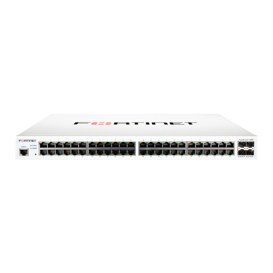
Page 25: Front-Panel Components
SFP interfaces. 1.5 Rear Panel Description The rear panel of the switch contains an AC power connector and a slot to plug in the 10 GE daughter board. -
Page 26: Management Options
Telnet, a Web Browser, or SNMP. 1.7 Web-based Management Interface After you have successfully installed the switch, you can configure the switch, monitor the LED panel, and display statistics graphically using a Web browser, such as Netscape Navigator (version 6.2 and higher) or Microsoft® Internet Explorer (version 5.0). - Page 27 RFC 2787 (VRRP-MIB) • RFC 3289 - DIFFSERV-DSCP-TC • RFC 3289 - DIFFSERV-MIB • QOS-DIFFSERV-EXTENSIONS-MIB • QOS-DIFFSERV-PRIVATE-MIB • RFC2674 802.1p • RFC 2932 (IPMROUTE-MIB) • Fortinet Enterprise MIB • ROUTING-MIB • MGMD-MIB • RFC 2934 PIM-MIB • DVMRP-STD-MIB • IANA-RTPROTO-MIB • MULTICAST-MIB...
-
Page 28: Installation And Quick Startup
2. Set the switch on a flat surface and check for proper ventilation. Allow at least 5 cm (2 inches) on each side of the switch and 15 cm (6 inches) at the back for the power cable. -
Page 29: Installing The Switch In A Rack
You can install the switch in most standard 19-inch (48.3-cm) racks. Refer to the illustrations below. 1. Use the supplied screws to attach a mounting bracket to each side of the switch. 2. Align the holes in the mounting bracket with the holes in the rack. -
Page 30: Quick Starting The Switch
2.3 Quick Starting the Switch 1. Read the device Installation Guide for the connectivity procedure. In-band connectivity allows access to the FortiSwitch- 100 switch locally or from a remote workstation. The device must be configured with IP information (IP address, subnet mask, and default gateway). -
Page 31: Quick Start Up User Account Management
User Access Mode - Shows whether the user is able to change parameters on the switch (Read/Write) or is only able to view (Read Only). As a factory default, admin has Read/Write access and guest has Read Only access. -
Page 32: Quick Start Up Ip Address
This will save passwords and all other changes to the device. If you do not save the running config, all changes will be lost when a power cycle is performed on the switch or when the switch is reset. Notes •... -
Page 33: Quick Start Up Uploading From Switch To Out-Of-Band Pc (Only Xmodem)
2.4.5 Quick Start up Uploading from Switch to Out-of-Band PC (Only XMODEM) Table 2-5. Quick Start up Uploading from Switch to Out-of-Band PC (XMODEM) Command copy startup-config <filename> xmodem Displays the Network Configurations IP Address - IP Address of the interface Default IP is 0.0.0.0... -
Page 34: Quick Start Up Downloading From Out-Of-Band Pc To Switch (Only Xmodem)
2.4.6 Quick Start up Downloading from Out-of-Band PC to Switch (Only XMODEM) Table 2-6 Quick Start up Downloading from Out-of-Band PC to Switch copy xmodem startup-config <filename> 2.4.7 Quick Start up Downloading from TFTP Server Before starting a TFTP server download, the operator must complete the Quick Start up for the IPAddress. -
Page 35: Connecting Devices To The Switch
Note: Images are loaded onto the switch from your local TFTP server, so start by downloading the appropriate image file from the Fortinet support portal to your local TFTP server, then follow the steps below. 1. Ensure that there is room on the switch for the updated image file:... - Page 36 If you are not using DHCP to automatically assign an IP address to the FortiSwitch, follow the steps below to configure a static IP address on the switch, substituting the appropriate IP address for the example shown. If you do not know what IP address to assign to the switch, contact your IT department.
- Page 37 Note: When configuring a static IP address, you must also configure a default gateway. Use the following commands, substituting the appropriate default gateway address for the example: (FortiSwitch-100_238) (if-vlan 1)#exit (FortiSwitch-100_238) (Config)#ip default-gateway 172.18.20.1 (FortiSwitch-100_238) (Config)#ex (FortiSwitch-100_238) #show ip interface IP Address...
- Page 38 2008/05/20 ---------- -------------------------------- -------------- ------- ----------- Total: 5 files. Now you are finished with the upgrade procedure! Please reload the switch and configure as desired. Troubleshooting the Download Procedure If you have configured an IP address (statically or via DHCP) on the FortiSwitch and still cannot download the image file, try the following: •...
-
Page 39: Set Up Your Switch Using Console Access
These components include a CPU, memory for data storage, other related hardware, and SNMP agent firmware. Activities on the switch can be monitored with these components, while the switch can be manipulated to carry out specific tasks. -
Page 40: Set Up Your Switch Using Telnet Access
2.6 Set Up your Switch Using Telnet Access Once you have set an IP address for your switch, you can use a Telnet program (in a VT-100 compatible terminal mode) to access and control the switch. Most of the screens are identical,... -
Page 41: Web-Based Management Interface
Web interface. When you configure the switch for the first time from the console, you can assign an IP address and subnet mask to the switch. Thereafter, you can access the switch’s Web interface directly using your Web browser by entering the switch’s IP address into the address bar. -
Page 42: Web-Based Management Menu
4. Type the default user name of admin and default of no password, or whatever password you have set up. Once you have entered your access point name, your Web browser automatically finds the FortiSwitch-100 Managed Switch and display the home page, as shown below. 3.3 Web-Based Management Menu Figure 4-3: System Information page This above page displays system information, such as: •... - Page 43 The Secondary Menus under the Main Menu contain a host of options that you can use to configure your switch. The online help contains a detailed description of the features on each screen. You can click the ‘help’ or the question mark at the top right of each screen to view the help menu topics.
- Page 44 • IGMP — see “IGMP Commands” • Multicast — see “Multicast Commands” • MDebug — see “Multicast Commands” • PIM-DM — see “PIM-DM Commands” • PIM-SM — see “PIM-SM Commands” System-Wide Popup Menus The FortiSwitch-100 Managed Switch also provides several popup menus.
- Page 45 Figure 4-5: System-wide menus You can also access the main navigation menu by right clicking on the image of the switch and browsing to the menu you want to use. Port-Specific Popup Menus The FortiSwitch-100 Managed Switch also provides several popup menus for each port.
-
Page 46: Command Line Interface Structure And Mode-Based Cli
4 Command Line Interface Structure and Mode-based CLI The Command Line Interface (CLI) syntax, conventions, and terminology are described in this section. Each CLI command is illustrated using the structure outlined below. 4.1 CLI Command Format Commands are followed by values, parameters, or both. Example 1 IP address <ipaddr>... - Page 47 The {} curly braces indicate that a parameter must be chosen from the list of choices. Values ipaddr This parameter is a valid IP address, made up of four decimal bytes ranging from 0 to 255. The default for all IP parameters consists of zeros (that is, 0.0.0.0). The interface IP address of 0.0.0.0 is invalid.
- Page 48 Empty strings (““) are not valid user defined strings. Command completion finishes spelling the command when enough letters of a command are typed to uniquely identify the command word. The command may be executed by typing <enter> (command abbreviation) or the command word may be completed by typing the <tab> or <space bar> (command completion).
-
Page 49: Switching Commands
Privileged Exec Display Message MAC Address: A unicast MAC address for which the switch has forwarding and/or filtering information. The format is 6 two-digit hexadecimal numbers that are separated by colons. For example: 00:23:45:67:89:AB IP Address: The IP address assigned to each interface. -
Page 50: Show Eventlog
File: The file in which the event originated. Line: The line number of the event. Task Id: The task ID of the event. Code: The event code. Time: The time this event occurred. Note: Event log information is retained across a switch reset. -
Page 51: Show Running-Config
The output is displayed in script format, which can be used to configure another switch with the same configuration. When a script name is provided, the output is redirected to a configuration script. The option [all] will also enable the display/capture of all commands with settings/configurations that include values that are same as the default values. -
Page 52: Show Hardware
Boot Rom Version: The release version maintenance number of the boot ROM code currently running on the switch. For example, if the release was 1, the version was 2, and the maintenance number was 4, the format would be '1.2.4'. -
Page 53: Show Loginsession
User Name: The name the user will use to login using the serial port or Telnet. A new user may be added to the switch by entering a name in a blank entry. The user name may be up to 8 characters, and is not case sensitive. -
Page 54: Show Interface Counters
<slot/port> - is the desired interface number. all - This parameter displays information for all interfaces. Default Setting None Command Mode Privileged Exec Display Message Intf: The physical slot and physical port. Type: If not blank, this field indicates that this port is a special type of port. The possible values are: Source - This port is a monitoring port. - Page 55 This command displays detailed statistics for a specific port or for all CPU traffic based upon the argument. Syntax show interface counters detailed {<slot/port> | switchport} <slot/port> - is the desired interface number. switchport - This parameter specifies whole switch or all interfaces. Default Setting None...
- Page 56 Command Mode Privileged Exec Display Message The display parameters when the argument is ' <slot/port>' are as follows: Total Packets Received (Octets): The total number of octets of data (including those in bad packets) received on the network (excluding framing bits but including FCS octets). This object can be used as a reasonable estimate of Ethernet utilization.
- Page 57 Total Packets Received Without Errors Unicast Packets Received: The number of subnetwork-unicast packets delivered to a higher-layer protocol. Multicast Packets Received: The total number of good packets received that were directed to a multicast address. Note that this number does not include packets directed to the broadcast address. Broadcast Packets Received: The total number of good packets received that were directed to the broadcast address.
- Page 58 Broadcast Packets Transmitted: The total number of packets that higher-level protocols requested be transmitted to the Broadcast address, including those that were discarded or not sent. Total Transmit Errors FCS Errors: The total number of packets transmitted that had a length (excluding framing bits, but including FCS octets) of between 64 and 1518 octets, inclusive, but had a bad FCS with an integral number of octets Tx Oversized: The total number of frames that exceeded the max permitted frame size.
-
Page 59: Show Interface Switch
Address Table for this switch. Maximum VLAN Entries: The maximum number of Virtual LANs (VLANs) allowed on this switch. Most VLAN Entries Ever Used: The largest number of VLANs that have been active on this switch since the last reboot. -
Page 60: Interface
Address Entries Currently In Use: The total number of Forwarding Database Address Table entries now active on the switch, including learned and static entries. VLAN Entries Currently In Use: The number of VLAN entries presently occupying the VLAN table. -
Page 61: Negotiate
speed-duplex {10 | 100} {full-duplex | half-duplex} 100 - 100BASE-T 10 - 10BASE-T full-duplex - Full duplex half-duplex - Half duplex Default Setting None Command Mode Interface Config This command is used to set the speed and duplex mode for all interfaces. Syntax speed-duplex all {10 | 100} {full-duplex | half-duplex} 100 - 100BASE-T... -
Page 62: Capabilities
negotiate no negotiate no - This command disables automatic negotiation on a port. Default Setting Enable Command Mode Interface Config This command enables automatic negotiation on all interfaces. The default value is enabled. Syntax negotiate all no negotiate all all - This command represents all interfaces. no - This command disables automatic negotiation on all interfaces. -
Page 63: Storm-Control Flowcontrol
- This command removes the advertised capability with using parameter Default Setting 10 half-duplex, 10 full-duplex, 100 half-duplex, 100 full-duplex, and 1000 full-duplex Command Mode Global Config 5.2.1.8 storm-control flowcontrol This command enables 802.3x flow control for the switch. -
Page 64: Shutdown
Note: This command only applies to full-duplex mode ports. Syntax storm-control flowcontrol no storm-control flowcontrol no - This command disables 802.3x flow control for the switch. Default Setting Disabled Command Mode Global Config This command enables 802.3x flow control for the specific interface. - Page 65 Syntax shutdown no shutdown no - This command enables a port. Default Setting Enabled Command Mode Interface Config This command is used to disable all ports. Syntax shutdown all no shutdown all all - This command represents all ports. no - This command enables all ports. Default Setting Enabled Command Mode...
-
Page 66: L2 Mac Address And Multicast Forwarding Database Tables
It is identified with interface 3/1 and is currently used when enabling VLANs for routing. Self: The value of the corresponding instance is the address of one of the switch’s physical interfaces (the system’s own MAC address). -
Page 67: Show Mac-Address-Table Gmrp
Privileged Exec Display Message Mac Address: A unicast MAC address for which the switch has forwarding and/or filtering information. The format is 6 or 8 two-digit hexadecimal numbers that are separated by colons, for example 01:23:45:67:89:AB. In an IVL system the MAC address will be displayed as 8 bytes. In an SVL system, the MAC address will be displayed as 6 bytes. -
Page 68: Show Mac-Address-Table Multicast
Privileged Exec Display Message Mac Address: A unicast MAC address for which the switch has forwarding and/or filtering information. The format is 6 or 8 two-digit hexadecimal numbers that are separated by colons, for example 01:23:45:67:89:AB. In an IVL system the MAC address will be displayed as 8 bytes. In an SVL system, the MAC address will be displayed as 6 bytes. -
Page 69: Show Mac-Address-Table Stats
5.2.2.5 show mac-address-table stats This command displays the MFDB statistics. Syntax show mac-address-table stats Default Setting None Command Mode Privileged Exec Display Message Max MFDB Table Entries: This displays the total number of entries that can possibly be in the MFDB. Most MFDB Entries Since Last Reset: This displays the largest number of entries that have been present in the Multicast Forwarding Database table. -
Page 70: Vlan Management
Syntax mac-address-table aging-time <10-1000000> no mac-address-table aging-time <10-1000000> <10-1000000> - aging-time (Range: 10-1000000) in seconds no - This command sets the forwarding database address aging timeout to 300 seconds. Default Setting Command Mode Global Config 5.2.3 VLAN Management 5.2.3.1 show vlan This command displays brief information on a list of all configured VLANs. -
Page 71: Show Vlan Id
5.2.3.2 show vlan id This command displays detailed information, including interface information, for a specific VLAN. Syntax show vlan {id <vlanid> | name <vlanname>} <vlanid> - VLAN ID (Range: 1 – 3965) <vlanname> - vlan name (up to 16 alphanumeric characters) Default Setting None Command Mode... -
Page 72: Show Protocol Group
5.2.3.3 show protocol group This command displays the Protocol-Based VLAN information for either the entire system, or for the indicated Group. Syntax show protocol group {<group-name> | all} <group-name> - The group name of an entry in the Protocol-based VLAN table. all –... -
Page 73: Vlan Database
Command Mode Privileged Exec Display Message Slot/port: Indicates by slot id and port number which port is controlled by the fields on this line. It is possible to set the parameters for all ports by using the selectors on the top line. Port VLAN ID: The VLAN ID that this port will assign to untagged frames or priority tagged frames received on this port. -
Page 74: Vlan Name
vlan <vlanid> [<name>] no vlan <vlanid> <vlanid> - VLAN ID (Range: 2 –3965). <name> - Configure an optional VLAN Name (a character string of 1 to 32 alphanumeric characters). no - This command deletes an existing VLAN. The ID is a valid VLAN identification number (ID 1 is reserved for the default VLAN). -
Page 75: Vlan Makestatic
5.2.3.8 vlan makestatic This command changes a dynamically created VLAN (one that is created by GVRP registration) to a static VLAN (one that is permanently configured and defined). The ID is a valid VLAN identification number. VLAN range is 2-3965. Syntax vlan makestatic <vlanid>... -
Page 76: Switchport Acceptable-Frame-Type
5.2.3.10 switchport acceptable-frame-type This command sets the frame acceptance mode per interface. For VLAN Only mode, untagged frames or priority frames received on this interface are discarded. For Admit All mode, untagged frames or priority frames received on this interface are accepted and assigned the value of the interface VLAN ID for this port. -
Page 77: Switchport Ingress-Filtering
interface VLAN ID for this port. With either option, VLAN tagged frames are forwarded in accordance with the IEEE 802.1Q VLAN Specification. Default Setting Admit all Command Mode Global Config 5.2.3.11 switchport ingress-filtering This command enables ingress filtering. If ingress filtering is disabled, frames received with VLAN IDs that do not match the VLAN membership of the receiving interface are admitted and forwarded to ports that are members of that VLAN. -
Page 78: Switchport Native Vlan
no switchport ingress-filtering all all - All interfaces. no - This command disables ingress filtering for all ports. If ingress filtering is disabled, frames received with VLAN IDs that do not match the VLAN membership of the receiving interface are admitted and forwarded to ports that are members of that VLAN. -
Page 79: Switchport Allowed Vlan
<vlanid> - VLAN ID (Range: 1 –3965). all - All interfaces. no - This command sets the VLAN ID for all interfaces to 1. Default Setting Command Mode Global Config 5.2.3.13 switchport allowed vlan This command configures the degree of participation for a specific interface in a VLAN. The ID is a valid VLAN identification number, and the interface is a valid interface number. -
Page 80: Switchport Tagging
switchport allowed vlan {add {tagged | untagged} | remove} all <vlanid> <vlanid> - VLAN ID (Range: 1 –3965). all - All interfaces. add - The interface is always a member of this VLAN. This is equivalent to registration fixed. tagged - all frames transmitted for this VLAN will be tagged. untagged - all frames transmitted for this VLAN will be untagged. -
Page 81: Switchport Priority
This command configures the tagging behavior for all interfaces in a VLAN to be enabled. If tagging is enabled, traffic is transmitted as tagged frames. If tagging is disabled, traffic is transmitted as untagged frames. The ID is a valid VLAN identification number. Syntax switchport tagging all <vlanid>... -
Page 82: Switchport Protocol Group
This command configures the port priority assigned for untagged packets for all ports presently plugged into the device. Any subsequent per port configuration will override this configuration setting. Syntax switchport priority all <0-7> <0-7> - The range for the priority is 0-7. all –... - Page 83 This command adds a protocol-based VLAN group to the system. The <group-name> is a character string of 1 to 16 characters. When it is created, the protocol group will be assigned a unique number that will be used to identify the group in subsequent commands. Syntax switchport protocol group <group-name>...
-
Page 84: Switchport Forbidden Vlan
Default Setting None Command Mode Global Config This command adds the <protocol> to the protocol-based VLAN identified by <group-name>. A group may have more than one protocol associated with it. Each interface and protocol combination can only be associated with one group. If adding a protocol to a group causes any conflicts with interfaces currently associated with the group, this command will fail, and the protocol will not be added to the group. -
Page 85: Gvrp And Bridge Extension
Syntax switchport forbidden vlan {add | remove} <vlanid> no switchport forbidden <vlanid> - VLAN ID (Range: 1 –3965). add - VLAND ID to add. remove - VLAND ID to remove. no - Remove the list of forbidden VLANs. Default Setting None Command Mode Interface Config... -
Page 86: Show Gvrp Configuration
5.2.4.2 show gvrp configuration This command displays Generic Attributes Registration Protocol (GARP) information for one or all interfaces. Syntax show gvrp configuration {<slot/port> | all} <slot/port> - An interface number. all - All interfaces. Default Setting None Command Mode Privileged Exec Display Message Interface: This displays the slot/port of the interface that this row in the table describes. -
Page 87: Show Gmrp Configuration
5.2.4.3 show gmrp configuration This command displays Generic Attributes Registration Protocol (GARP) information for one or All interfaces. Syntax show gmrp configuration {<slot/port> | all} <slot/port> - An interface number. all - All interfaces. Default Setting None Command Mode Privileged Exec Display Message Interface: This displays the slot/port of the interface that this row in the table describes. -
Page 88: Bridge-Ext Gvrp
Syntax show garp configuration {<slot/port> | all} <slot/port> - An interface number. all - All interfaces. Default Setting None Command Mode Privileged Exec Display Message Interface: This displays the slot/port of the interface that this row in the table describes. GVRP Mode: Indicates the GVRP administrative mode for the port. -
Page 89: Bridge-Ext Gmrp
5.2.4.6 bridge-ext gmrp This command enables GARP Multicast Registration Protocol (GMRP) on the system. The default value is disabled. Syntax bridge-ext gmrp no bridge-ext gmrp no - This command disables GARP Multicast Registration Protocol (GMRP) on the system. Default Setting Disabled Command Mode Global Config... -
Page 90: Switchport Gmrp
This command enables GVRP (GARP VLAN Registration Protocol) for all ports. Syntax switchport gvrp all no switchport gvrp all all - All interfaces. no - This command disables GVRP (GARP VLAN Registration Protocol) for all ports. If GVRP is disabled, Join Time, Leave Time, and Leave All Time have no effect. -
Page 91: Garp Timer
Interface Config This command enables GMRP Multicast Registration Protocol on all interfaces. If an interface which has GMRP enabled is enabled for routing or is enlisted as a member of a port-channel (LAG), GMRP functionality will be disabled on that interface. GMRP functionality will subsequently be re-enabled if routing is disabled and port-channel (LAG) membership is removed from an interface that has GMRP enabled. - Page 92 no - This command sets the GVRP join time per port and per GARP to 20 centiseconds (0.2 seconds). This command has an effect only when GVRP and GMRP are enabled. Default Setting 20 centiseconds (0.2 seconds) Command Mode Interface Config This command sets the GVRP join time for all ports and per GARP.
- Page 93 Note: This command has an effect only when GVRP and GMRP are enabled. Syntax garp timer leave < 20-600 > no garp timer leave <20-600> - leave time (Range: 20 – 600) in centiseconds. no - This command sets the GVRP leave time per port to 60 centiseconds (0.6 seconds). Note: This command has an effect only when GVRP and GMRP are enabled.
- Page 94 Default Setting 60 centiseconds (0.6 seconds) Command Mode Global Config This command sets how frequently Leave All PDUs are generated per port. A Leave All PDU indicates that all registrations will be unregistered. Participants would need to rejoin in order to maintain registration.
-
Page 95: Igmp Snooping
Syntax garp timer leaveall all < 200-6000 > no garp timer leaveall all <200-6000> - leave time (Range: 200 – 6000) in centiseconds. all - All interfaces. no - This command sets how frequently Leave All PDUs are generated for all ports to 1000 centiseconds (10 seconds). -
Page 96: Show Ip Igmp Snooping Mrouter
Display Message Admin Mode: This indicates whether or not IGMP Snooping is active on the switch. Multicast Control Frame Count: This displays the number of multicast control frames that are processed by the CPU. Interfaces Enabled for IGMP Snooping: This is the list of interfaces on which IGMP Snooping is enabled. -
Page 97: Show Ip Igmp Snooping
Group Membership Interval Time The Group Membership Interval time is the amount of time in seconds that a switch will wait for a report from a particular group on a particular interface, which is participating in the VLAN, before deleting the interface from the entry.This value may be configured... -
Page 98: Configuration Commands
Max Response Time This displays the amount of time the switch will wait after sending a query on an interface, participating in the VLAN, because it did not receive a report for a particular group on that interface. This value may be configured. - Page 99 Default Setting 260 seconds Command Mode Global Config, Interface Config ip igmp snooping interfacemode This command enables IGMP Snooping on a selected interface. If an interface which has IGMP Snooping enabled is enabled for routing or is enlisted as a member of a port-channel (LAG), IGMP Snooping functionality will be disabled on that interface.
-
Page 100: Ip Igmp Snooping Mcrtrexpiretime
This command sets the Multicast Router Present Expiration time on the system. This is the amount of time in seconds that a switch will wait for a query to be received on an interface before the interface is removed from the list of interfaces with multicast routers attached. The range is 0 to 3600 seconds. - Page 101 This command enables or disables IGMP Snooping fast-leave admin mode on a selected interface or on all interfaces. Enabling fastleave allows the switch to immediately remove the layer 2 LAN interface from its forwarding table entry upon receiving an IGMP leave message for that multicast group without first sending out MAC-based general queries to the interface(s).
-
Page 102: Ip Igmp Snooping Mrouter
ip igmp snooping mrouter This command configures a selected interface as a multicast router interface. When configured as a multicast router interface, the interface is treated as a multicast router interface in all VLANs. Syntax ip igmp snooping mrouter interface no ip igmp snooping mrouter interface no - This command disables the status of the interface as a statically configured multicast router interface. -
Page 103: Ip Igmp Snooping Vlan Static
Command Mode Interface Config. ip igmp snooping vlan static This command is used to add a port to a multicast group. Syntax ip igmp snooping vlan <vlanid> static <macaddr> interface <slot/port> <vlanid> - VLAN ID (Range: 1 – 3965). <macaddr> - Multicast group MAC address. <slot/port>... -
Page 104: Set Igmp Maxresponse
This command sets the IGMP Group Membership Interval on a particular VLAN. The Group Membership Interval time is the amount of time in seconds that a switch will wait for a report from a particular group on a particular interface, which is participating in the VLAN, before deleting the interface from the entry. -
Page 105: Set Igmp Mcrtexpiretime
This command sets the Multicast Router Present Expiration time on a particular VLAN. This is the amount of time in seconds that a switch will wait for a query to be received on an interface, which is participating in the VLAN, before the interface is removed from the list of interfaces with multicast routers attached. - Page 106 This command enables or disables IGMP Snooping fast-leave admin mode on a selected VLAN. Enabling fastleave allows the switch to immediately remove the layer 2 LAN interface, participating in the VLAN, from its forwarding table entry upon receiving an IGMP leave message for that multicast group without first sending out MAC-based general queries to the interface.
-
Page 107: Port Channel
Mbr Ports: This field lists the ports that are members of this port-channel, in slot/port notation. Active Ports: This field lists the ports that are actively participating in this port-channel. This command displays an overview of all port-channels (LAGs) on the switch. Syntax show port-channel {<logical slot/port>... -
Page 108: Port-Channel
Display Message Log. Intf: The logical slot and the logical port. Port-Channel Name: The name of this port-channel (LAG). You may enter any string of up to 15 alphanumeric characters. Link : Indicates whether the Link is up or down. Admin Mode: May be enabled or disabled. -
Page 109: Port-Channel Adminmode All
Command Usage 1. Max number of port-channels could be created by user are 6 and Max. Number of members for each port-channel are 8. 5.2.6.3 port-channel adminmode all This command sets every configured port-channel with the same administrative mode setting. Syntax port-channel adminmode all no port-channel adminmode all... -
Page 110: Port-Channel Linktrap
Default Setting Disabled Command Mode Interface Config 5.2.6.5 port-channel linktrap This command enables link trap notifications for the port-channel (LAG). The interface is a logical slot and port for a configured port-channel. The option all sets every configured port-channel with the same administrative mode setting. Syntax port-channel linktrap {<logical slot/port>... -
Page 111: Adminmode
port-channel name {<logical slot/port> | all} <name> <logical slot/port> - Port-Channel Interface number. all - all Port-Channel interfaces. <name> - Configured Port-Channel name (up to 15 characters). Default Setting None Command Mode Global Config 5.2.6.7 adminmode This command enables a port-channel (LAG) members. The interface is a logical slot and port for a configured port-channel. -
Page 112: Channel-Group
Syntax lacp no lacp no - This command disables Link Aggregation Control Protocol (LACP) on a port. Default Setting Enabled Command Mode Interface Config This command enables Link Aggregation Control Protocol (LACP) on all ports. Syntax lacp all no lacp all all - All interfaces. -
Page 113: Delete-Channel-Group
Note: Before adding a port to a port-channel, set the physical mode of the port. See ‘speed’ command. Syntax channel-group <logical slot/port> <logical slot/port> - Port-Channel Interface number. Default Setting None Command Mode Interface Config Command Usage 1. The maximum number of members for each Port-Channel is 6. 5.2.6.10 delete-channel-group This command deletes the port from the port-channel (LAG). -
Page 114: Storm Control
Syntax delete-channel-group <logical slot/port> all <logical slot/port> - Port-Channel Interface number. all - All members for specific Port-Channel. Default Setting None Command Mode Global Config 5.2.7 Storm Control 5.2.7.1 show storm-control This command is used to display broadcast storm control information. Syntax show storm-control broadcast Default Setting... - Page 115 This command is used to display multicast storm control information. Syntax show storm-control multicast Default Setting None Command Mode Privileged Exec Display Message Intf: Displays interface number. Mode: Displays status of storm control multicast. Level: Displays level for storm control multicast Rate: Displays rate for storm control multicast.
-
Page 116: Storm-Control Broadcast
(as represented in “Broadcast Storm Recovery Thresholds” table) of the link speed, the switch discards the broadcasts traffic until the broadcast traffic returns to the threshold percentage or less. The full implementation is depicted in the “Broadcast Storm Recovery Thresholds”... -
Page 117: Storm-Control Multicast
Disabled Command Mode GlobaI Config 5.2.7.3 storm-control multicast This command enables multicast storm recovery mode on the selected interface. Syntax storm-control multicast no storm-control multicast no - This command disables multicast storm recovery mode on the selected interface. Default Setting None Command Mode Interface Config... -
Page 118: Storm-Control Unicast
5.2.7.4 storm-control unicast This command enables unicast storm recovery mode on the selected interface. Syntax storm-control unicast no storm-control unicast no - This command disables unicast storm recovery mode on the selected interface. Default Setting None Command Mode Interface Config This command enables unicast storm recovery mode on all interfaces. -
Page 119: Switchport Broadcast Packet-Rate
5.2.7.5 switchport broadcast packet-rate This command will protect your network from broadcast storms by setting a threshold level for broadcast traffic on each port. Syntax switchport broadcast packet-rate {1 | 2 | 3 | 4} 1 - Threshold level represents 64 pps for 1G Port or 1042 pps for 10G port. 2 - Threshold level represents 128 pps for 1G Port or 2084 pps for 10G port. -
Page 120: Switchport Multicast Packet-Rate
Level 4 Command Mode Global Config 5.2.7.6 switchport multicast packet-rate This command will protect your network from multicast storms by setting a threshold level for multicast traffic on each port. Syntax switchport multicast packet-rate {1 | 2 | 3 | 4} 1 - Threshold level represents 64 pps for 1G Port or 1042 pps for 10G port. -
Page 121: Switchport Unicast Packet-Rate
all - This command represents all interfaces. Note: pps (packet per second) Default Setting Level 4 Command Mode Global Config 5.2.7.7 switchport unicast packet-rate This command will protect your network from unicast storms by setting a threshold level for unicast traffic on each port. Syntax switchport unicast packet-rate {1 | 2 | 3 | 4} 1 - Threshold level represents 64 pps for 1G Port or 1042 pps for 10G port. -
Page 122: L2 Priority
switchport unicast all packet-rate {1 | 2 | 3 | 4} 1 - Threshold level represents 64 pps for 1G Port or 1042 pps for 10G port. 2 - Threshold level represents 128 pps for 1G Port or 2084 pps for 10G port. 3 - Threshold level represents 256 pps for 1G Port or 3124 pps for 10G port. -
Page 123: Queue Cos-Map
5.2.8.2 queue cos-map This command is used to assign class of service (CoS) value to the CoS priority queue. Syntax queue cos-map <priority> <queue-id> no queue cos-map <queue-id> - The queue id of the CoS priority queue (Range: 0 - 7 ). <priority>... -
Page 124: Port-Monitor Session
Default Setting None Command Mode Privileged Exec Display Message Session ID: indicates the session ID. Admin Mode: indicates whether the Port Monitoring feature is enabled or disabled. The possible values are enabled and disabled. Probe Port: is the slot/port that is configured as the probe port. If this value has not been configured, 'Not Configured' will be displayed. -
Page 125: Port-Monitor Session Mode
5.3.1.1 show ip interface This command displays configuration settings associated with the switch's network interface. The network interface is the logical interface used for in-band connectivity with the switch via any of the switch's front panel ports. The configuration parameters associated with the switch's network interface do not affect the configuration of the front panel ports through which traffic is switched or routed. -
Page 126: Show Ip Filter
Web Port: This field is used to set the HTTP Port Number. The value must be in the range of 1 to 65535. Port 80 is the default value. Java Mode: Specifies if the switch should allow access to the Java applet in the header frame. Enabled means the applet can be viewed. The factory default is disabled. -
Page 127: Show Ip Ipv6
5.3.1.3 show ip ipv6 This command displays the IPv6 forwarding status of all ports. Syntax show ip ipv6 Default Setting None Command Mode Privileged Exec Display Message Intf: Interface number Type: Status of each interface for IPv6. 5.3.1.4 mtu This command sets the maximum transmission unit (MTU) size (in bytes) for physical and port-channel (LAG) interfaces. -
Page 128: Interface Vlan
5.3.1.5 interface vlan This command is used to enter Interface-vlan configuration mode. Syntax interface vlan <vlanid> <vlanid> - VLAN ID (Range: 1 - 3965). Default Setting None Command Mode Global Config 5.3.1.6 ip address This command sets the IP Address, and subnet mask. The IP Address and the gateway must be on the same subnet. -
Page 129: Ip Default-Gateway
Interface-Vlan Config Command Usage Once the IP address is set, the VLAN ID’s value will be assigned to management VLAN. 5.3.1.7 ip default-gateway This command sets the IP Address of the default gateway. Syntax ip default-gateway <gateway> no ip default-gateway <... -
Page 130: Ip Filter
<dhcp> - Obtains IP address from DHCP. <none> - Obtains IP address by setting configuration. Default Setting None Command Mode Interface-Vlan Config 5.3.1.9 ip filter This command is used to enable the IP filter function. Syntax ip filter no ip filter no –... -
Page 131: Ip Ipv6
Default Setting None Command Mode Global Config 5.3.1.10 ip ipv6 This command is used to enable the Ipv6 function on specific interface. Syntax ip ipv6 no ip ipv6 no - disable IPv6. Default Setting Enabled Command Mode Interface Config This command is used to enable the Ipv6 function on all interfaces. Syntax ip ipv6 all no ip ipv6 all... -
Page 132: Serial Interface Commands
Serial Port Login Timeout (minutes): Specifies the time, in minutes, of inactivity on a Serial port connection, after which the switch will close the connection. Any numeric value between 0 and 160 is allowed, the factory default is 5. A value of 0 disables the timeout. -
Page 133: Baudrate
Syntax line console Default Setting None Command Mode Global Config 5.3.2.3 baudrate This command specifies the communication rate of the terminal interface. The supported rates are 1200, 2400, 4800, 9600, 19200, 38400, 57600, 115200. Syntax baudrate {1200 | 2400 | 4800 | 9600 | 19200 | 38400 | 57600 | 115200} no baudrate no - This command sets the communication rate of the terminal interface to 115200. -
Page 134: Password-Threshold
<0-160> - max connect time (Range: 0 -160). no - This command sets the maximum connect time (in minutes) without console activity to 5. Default Setting Command Mode Line Config 5.3.2.5 password-threshold This command is used to set the password instruction threshold limiting the number of failed login attempts. -
Page 135: Telnet Session Commands
<0-65535> - silent time (Range: 0 - 65535) in seconds. no - This command sets the maximum value to the default. Default Setting Command Mode Line Config 5.3.3 Telnet Session Commands 5.3.3.1 telnet This command establishes a new outbound telnet connection to a remote host. Syntax telnet <host>... -
Page 136: Line Vty
Syntax show line vty Default Setting None Command Mode Privileged Exec Display Message Remote Connection Login Timeout (minutes): This object indicates the number of minutes a remote connection session is allowed to remain inactive before being logged off. A zero means there will be no timeout. -
Page 137: Exec-Timeout
5.3.3.4 exec-timeout This command sets the remote connection session timeout value, in minutes. A session is active as long as the session has been idle for the value set. A value of 0 indicates that a session remains active indefinitely. The time is a decimal value from 0 to 160. Note: Changing the timeout value for active sessions does not become effective until the session is reaccessed. -
Page 138: Maxsessions
Command Mode Telnet Config 5.3.3.6 maxsessions This command specifies the maximum number of remote connection sessions that can be established. A value of 0 indicates that no remote connection can be established. The range is 0 to 5. Syntax maxsessions <0-5> no maxsessions <0-5>... -
Page 139: Telnet Sessions
no - This command disables telnet sessions. If sessions are disabled, no new telnet sessions are established. Default Setting Enabled Command Mode Telnet Config 5.3.3.8 telnet sessions This command regulates new outbound telnet connections. If enabled, new outbound telnet sessions can be established until it reaches the maximum number of simultaneous outbound telnet sessions allowed. -
Page 140: Telnet Exec-Timeout
Syntax telnet maxsessions <0-5> no maxsessions <0-5> - max sessions (Range: 0 - 5). no - This command sets the maximum value to be 5. Default Setting Command Mode Global Config 5.3.3.10 telnet exec-timeout This command sets the outbound telnet session timeout value in minute. Note: Changing the timeout value for active sessions does not become effective until the session is reaccessed. -
Page 141: Show Telnet
The SNMP agent of the switch complies with SNMP versions 1, 2c, and 3 (for more about the SNMP specification, see the SNMP RFCs). The SNMP agent sends traps through TCP/IP to an external SNMP manager based on the SNMP configuration (the trap receiver and other SNMP community parameters). -
Page 142: Show Trapflags
If a trap condition is enabled and the condition is detected, the switch's SNMP agent sends the trap to all enabled trap receivers. The switch does not have to be reset to implement the changes. Cold and warm start traps are always generated and cannot be disabled. -
Page 143: Snmp-Server Sysname
Multiple Users Flag: May be enabled or disabled. The factory default is enabled. Indicates whether a trap will be sent when the same user ID is logged into the switch more than once at the same time (either via telnet or serial port). -
Page 144: Snmp-Server Contact
This command adds (and names) a new SNMP community. A community name is a name associated with the switch and with a set of SNMP managers that manage it with a specified privilege level. The length of the name can be up to 16 case-sensitive characters. - Page 145 This command activates an SNMP community. If a community is enabled, an SNMP manager associated with this community manages the switch according to its access right. If the community is disabled, no SNMP requests using this community are accepted. In this case the SNMP manager associated with this community cannot manage the switch until the Status is changed back to Enable.
- Page 146 The community name may be up to 16 alphanumeric characters. Default Setting 0.0.0.0 Command Mode Global Config This command restricts access to switch information. The access mode is read-only (also called public) or read/write (also called private). Syntax snmp-server community {ro | rw} <name> <name> - community name.
-
Page 147: Snmp-Server Host
<ro> - access mode is read-only. <rw> - access mode is read/write. Default Setting None Command Mode Global Config 5.3.4.7 snmp-server host This command sets a client IP address for an SNMP community. The address is the associated community SNMP packet sending address and is used along with the client IP mask value to denote a range of IP addresses from which SNMP clients may use that community to access the device. - Page 148 Enabled Command Mode Global Config This command enables Link Up/Down traps for the entire switch. When enabled, link traps are sent only if the Link Trap flag setting associated with the port is enabled (see ‘snmp trap link-status’ command). Syntax...
- Page 149 Default Setting Enabled Command Mode Global Config This command enables Multiple User traps. When the traps are enabled, a Multiple User Trap is sent when a user logs in to the terminal interface (EIA 232 or telnet) and there is an existing terminal interface session.
- Page 150 Global Config This command enables PIM traps. Syntax snmp-server enable traps pim no snmp-server enable traps pim no - This command disables PIM trap. Default Setting Enabled Command Mode Global Config This command enables the sending of new root traps and topology change notification traps. Syntax snmp-server enable traps stpmode no snmp-server enable traps stpmode...
-
Page 151: Snmp Trap Commands
This command displays SNMP trap receivers. Trap messages are sent across a network to an SNMP Network Manager. These messages alert the manager to events occurring within the switch or on the network. Six trap receivers are simultaneously supported. Syntax... - Page 152 no snmp trap link-status no - This command disables link status traps by interface. Note: This command is valid only when the Link Up/Down Flag is enabled. (See ‘snmpserver enable traps linkmode’ command.) Default Setting Disabled Command Mode Interface Config This command enables link status traps for all interfaces.
-
Page 153: Snmptrap
5.3.5.3 snmptrap <name> <ipaddr> This command adds an SNMP trap name. The maximum length of the name is 16 case-sensitive alphanumeric characters. Syntax snmptrap <name> <ipaddr> no snmptrap <name> <ipaddr> <name> - SNMP trap name (Range: up to 16 case-sensitive alphanumeric characters). <ipaddr>... -
Page 154: Snmptrap Mode
- This command deactivates an SNMP trap. Trap receivers are inactive (not able to receive traps). Default Setting None Command Mode Global Config 5.3.6 HTTP commands 5.3.6.1 show ip http This command displays the http settings for the switch. Syntax show ip http... -
Page 155: Ip Javamode
TSL1. 5.3.6.2 ip javamode This command specifies whether the switch should allow access to the Java applet in the header frame of the Web interface. When access is enabled, the Java applet can be viewed from the Web interface. When access is disabled, the user cannot view the Java applet. -
Page 156: Ip Http Server
Disabling the Web interface takes effect immediately. All interfaces are affected. Syntax ip http server no ip http server no - This command disables access to the switch through the Web interface. When access is disabled, the user cannot login to the switch's Web server. Default Setting Enabled... -
Page 157: Ip Http Secure-Port
5.3.6.5 ip http secure-port This command is used to set the SSLT port where port can be 1-65535 and the default is port 443. Syntax ip http secure-port <portid> no ip http secure-port <portid> - SSLT Port value. no - This command is used to reset the SSLT port to the default value. Default Setting Command Mode Global Config... -
Page 158: Ip Http Secure-Protocol
5.3.6.7 ip http secure-protocol This command is used to set protocol levels (versions). The protocol level can be set to TLS1, SSL3 or to both TLS1 and SSL3. Syntax ip http secure-protocol <protocollevel1> [protocollevel2] no ip http secure-protocol <protocollevel1> [protocollevel2] <protocollevel1 - 2>... -
Page 159: Ip Ssh
Max SSH Sessions Allowed: The maximum number of inbound SSH sessions allowed on the switch. SSH Timeout: This field is the inactive timeout value for incoming SSH sessions to the switch. 5.3.7.2 ip ssh This command is used to enable SSH. -
Page 160: Ip Ssh Maxsessions
5.3.7.4 ip ssh maxsessions This command specifies the maximum number of SSH connection sessions that can be established. A value of 0 indicates that no ssh connection can be established. The range is 0 to 5. Syntax ip ssh maxsessions <0-5> no ip ssh maxsessions <0-5>... -
Page 161: Dhcp Client Commands
None Command Mode Global Config 5.3.8.2 ip dhcp client-identifier This command is used to specify the DCHP client identifier for this switch. Use the no form to restore to default value. Syntax ip dhcp client-identifier {text <text> | hex <hex>}... -
Page 162: Dhcp Relay Commands
no ip dhcp client-identifier <text> - A text string. (Range: 1-15 characters). <hex> - The hexadecimal value (00:00:00:00:00:00). no - This command is used to restore to default value. Default Setting System Burned In MAC Address Command Mode Global Config 5.3.9 DHCP Relay Commands 5.3.9.1 Show bootpdhcprelay This command is used to display the DHCP relay agent configuration information on the... -
Page 163: Bootpdhcprelay Maxhopcount
Packets Discarded - The total number of BOOTP/DHCP packets discarded by this Relay Agent since the last time the switch was reset. 5.3.9.2 Bootpdhcprelay maxhopcount This command is used to set the maximum relay agent hops for BootP/DHCP Relay on the system. -
Page 164: Spanning Tree Commands
Show commands display spanning tree settings, statistics, and other information. Configuration Commands configure features and options of the switch. For every configuration command there is a show command that displays the configuration setting. 5.4.1 Show Commands 5.4.1.1 show spanning-tree... -
Page 165: Show Spanning-Tree Interface
Time Since Topology Change: In seconds. Topology Change Count: Number of times changed. Topology Change in progress: Boolean value of the Topology Change parameter for the switch indicating if a topology change is in progress on any port assigned to the common and internal spanning tree. -
Page 166: Show Spanning-Tree Vlan
Privileged Exec Display Message Port Mode: The administration mode of spanning tree. Port Up Time Since Counters Last Cleared: Time since the port was reset, displayed in days, hours, minutes, and seconds. STP BPDUs Transmitted: Spanning Tree Protocol Bridge Protocol Data Units sent. STP BPDUs Received: Spanning Tree Protocol Bridge Protocol Data Units received. - Page 167 Associated FIDs: List of forwarding database identifiers associated with this instance. Associated VLANs: List of VLAN IDs associated with this instance. This command displays summary information about all multiple spanning tree instances in the switch. On execution, the following details are displayed. Syntax show spanning-tree mst summary...
- Page 168 If 0 (defined as the default CIST ID) is passed as the <0-4094>, then this command displays the settings and parameters for a specific switch port within the common and internal spanning tree. The <slot/port> is the desired switch port. In this case, the following are displayed.
- Page 169 The parameter <0-4094> indicates a particular MST instance. The parameter {<slot/port> | all} indicates the desired switch port or all ports. If 0 (defined as the default CIST ID) is passed as the <0-4094>, then the status summary is displayed for one or all ports within the common and internal spanning tree.
-
Page 170: Show Spanning-Tree Summary
STP State: The forwarding state of the port in the specified spanning tree instance. Port Role: The role of the specified port within the spanning tree. 5.4.1.5 show spanning-tree summary This command displays spanning tree settings and parameters for the switch. The following details are displayed on execution of the command. Syntax... -
Page 171: Configuration Commands
Default Setting None Command Mode Privileged Exec Display Message Bridge Priority: Configured value. Bridge Identifier: The bridge ID of current Spanning Tree. Bridge Max Age: Configured value. Bridge Hello Time: Configured value. Bridge Forward Delay: Configured value. Bridge Hold Time: Minimum time between transmission of Configuration Bridge Protocol Data Units (BPDUs). -
Page 172: Spanning-Tree Configuration
Global Config 5.4.2.3 spanning-tree configuration This command sets the Configuration Identifier Name for use in identifying the configuration that this switch is currently using. The <name> is a string of at most 32 alphanumeric characters. Syntax spanning-tree configuration name <name>... -
Page 173: Spanning-Tree Mode
This command sets the Configuration Identifier Revision Level for use in identifying the configuration that this switch is currently using. The Configuration Identifier Revision Level is a number in the range of 0 to 65535. Syntax spanning-tree configuration revision <0-65535>... -
Page 174: Spanning-Tree Forward-Time
Command Mode Global Config 5.4.2.5 spanning-tree forward-time This command sets the Bridge Forward Delay parameter to a new value for the common and internal spanning tree. The forward-time value is in seconds within a range of 4 to 30, with the value being greater than or equal to "(Bridge Max Age / 2) + 1". -
Page 175: Spanning-Tree Max-Age
<1-10> - hellotime value (Range: 1 – 10). no - This command sets the Hello Time parameter for the common and internal spanning tree to the default value, that is, 2. Default Setting Command Mode Global Config 5.4.2.7 spanning-tree max-age This command sets the Bridge Max Age parameter to a new value for the common and internal spanning tree. -
Page 176: Spanning-Tree Mst
<1-4094> - multiple spanning tree instance ID. no - This command removes a multiple spanning tree instance from the switch and reallocates all VLANs allocated to the deleted instance to the common and internal spanning tree. The instance <1-4094> is a number that corresponds to the desired existing multiple spanning tree instance to be removed. - Page 177 This command sets the bridge priority for a specific multiple spanning tree instance. The instance <mstid> is a number that corresponds to the desired existing multiple spanning tree instance. The priority value is a number within a range of 0 to 61440 in increments of 4096. If 0 (defined as the default CIST ID) is passed as the <mstid>, then this command sets the Bridge Priority parameter to a new value for the common and internal spanning tree.
- Page 178 spanning-tree mst vlan <0-4094> <1-3965> no spanning-tree mst vlan <0-4094> <1-3965> <0-4094> - multiple spanning tree instance ID. <1-3965> - VLAN ID (Range: 1 – 3965). no - This command removes an association between a multiple spanning tree instance and a VLAN. The VLAN will again be associated with the common and internal spanning tree.
- Page 179 If the ‘cost’ token is specified, this command sets the path cost for this port within a multiple spanning tree instance or the common and internal spanning tree instance, depending on the <0-4094> parameter, to the default value, that is, a pathcost value based on the Link Speed. Default Setting Cost : auto Command Mode...
-
Page 180: Spanning-Tree Port Mode
This command sets the Administrative Switch Port State for this port to enabled. Syntax spanning-tree port mode no spanning-tree port mode no - This command sets the Administrative Switch Port State for this port to disabled. Default Setting Disabled Command Mode Interface Config This command sets the Administrative Switch Port State for all ports to enabled. -
Page 181: Spanning-Tree Edgeport
5.4.2.11 spanning-tree edgeport This command specifies that this port is an Edge Port within the common and internal spanning tree. This will allow this port to transition to Forwarding State without delay. Syntax spanning-tree edgeport no spanning-tree edgeport no - This command specifies that this port is not an Edge Port within the common and internal spanning tree. -
Page 182: Show Logging Buffered
Log Messages Relayed The number of messages that are relayed. Log Messages Ignored The number of messages that are ignored. 5.5.2 show logging buffered This command displays the message log maintained by the switch. The message log contains system trace information. Syntax... -
Page 183: Show Logging Hosts
Trap Log Capacity: The maximum number of traps that could be stored in the switch. Log: The sequence number of this trap. System Up Time: The relative time since the last reboot of the switch at which this trap occurred. Trap: The relevant information of this trap. -
Page 184: Configuration Commands
5.5.4 Configuration Commands 5.5.4.1 logging buffered This command enables logging to in-memory log where up to 128 logs are kept. Syntax logging buffered no logging buffered no - This command disables logging to in-memory log. Default Setting None Command Mode Privileged Exec This command enables wrapping of in-memory logging when full capacity reached. -
Page 185: Logging Console
5.5.4.2 logging console This command enables logging to the console. Syntax logging console [<severitylevel> | <0-7>] no logging console [<severitylevel> | <0-7>] - The value is specified as either an integer from 0 to 7 or symbolically through one of the following keywords: emergency (0), alert (1), critical (2), error (3), warning (4), notice (5), informational (6), debug (7). - Page 186 Default Setting None Command Mode Privileged Exec This command disables logging to hosts. Syntax logging host remove <hostindex> < hostindex > - Index of the log server. Default Setting None Command Mode Privileged Exec This command reconfigures the IP address of the log server. Syntax logging host reconfigure <hostindex>...
-
Page 187: Logging Syslog
Privileged Exec 5.5.4.4 logging syslog This command enables syslog logging. Syntax logging syslog no logging syslog no - Disables syslog logging. Default Setting None Command Mode Privileged Exec This command sets the local port number of the LOG client for logging messages. Syntax logging syslog port <portid>... -
Page 188: Clear Logging Buffered
5.6 Script Management Commands 5.6.1 script apply This command applies the commands in the configuration script to the switch. The apply command backs up the running configuration and then starts applying the commands in the script file. Application of the commands stops at the first failure of a command. -
Page 189: Script Delete
- Delete all scripts presented in the switch Default Setting None Command Mode Privileged Exec 5.6.3 script list This command lists all scripts present on the switch as well as the total number of files present. Syntax script list... -
Page 190: Script Show
Default Setting None Command Mode Privileged Exec 5.6.4 script show This command displays the content of a script file. Syntax script show <scriptname> <scriptname> - Name of the script file. Default Setting None Command Mode Privileged Exec 5.7 User Account Management Commands 5.7.1 Show Commands 5.7.1.1 show users This command displays the configured user names and their settings. -
Page 191: Configuration Commands
User Name: The name the user will use to login using the serial port, Telnet or Web. A new user may be added to the switch by entering a name in a blank entry. The user name may be up to eight characters, and is not case sensitive. Two users are included as the factory default, admin, and guest. -
Page 192: Username Snmpv3 Authentication
no username <username> <username> - is a new user name (Range: up to 8 characters). no - This command removes a user name created before. Note: The admin user account cannot be deleted. nopassword - This command sets the password of an existing operator to blank. When a password is changed, a prompt will ask for the operator's former password. -
Page 193: Username Snmpv3 Encryption
Global Config 5.7.2.3 username snmpv3 encryption This command specifies the encryption protocol and key to be used for the specified login user. The valid encryption protocols are none or des. The des protocol requires a key, which can be specified on the command line. The key may be up to 16 characters. If the des protocol is specified but a key is not provided, the user will be prompted to enter the key. -
Page 194: Show Authentication
Syntax show users authentication Default Setting None Command Mode Privileged Exec Display Message User: This field lists every user that has an authentication login list assigned. System Login: This field displays the authentication login list assigned to the user for system login. 802.1x: This field displays the authentication login list assigned to the user for 802.1x port security. -
Page 195: Show Authentication Users
5.8.1.4 show dot1x This command is used to show the status of the dot1x Administrative mode. Syntax show dot1x Default Setting None Command Mode Privileged Exec Display Message Administrative mode: Indicates whether authentication control on the switch is enabled or disabled. -
Page 196: Show Dot1X Detail
5.8.1.5 show dot1x detail This command is used to show a summary of the global dot1x configuration and the detailed dot1x configuration for a specified port. Syntax show dot1x detail <slot/port> <slot/port> - is the desired interface number. Default Setting None Command Mode Privileged Exec... -
Page 197: Show Dot1X Statistics
5.8.1.6 show dot1x statistics This command is used to show a summary of the global dot1x configuration and the dot1x statistics for a specified port. Syntax show dot1x statistics <slot/port> <slot/port> - is the desired interface number. Default Setting None Command Mode Privileged Exec Display Message... -
Page 198: Show Dot1X Summary
5.8.1.7 show dot1x summary This command is used to show a summary of the global dot1x configuration and summary information of the dot1x configuration for a specified port or all ports. Syntax show dot1x summary {<slot/port> | all} <slot/port> - is the desired interface number. all - All interfaces. -
Page 199: Show Radius-Servers
Type: Primary or secondary Secret Configured: Yes / No Message Authenticator: The message authenticator attribute configured for the radius server. 5.8.1.10 show radius This command is used to display the various RADIUS configuration items for the switch. Syntax show radius Default Setting... -
Page 200: Show Radius Accounting
Command Mode Privileged Exec Display Message Current Server IP Address: Indicates the configured server currently in use for authentication Number of configured servers: The configured IP address of the authentication server Number of retransmits: The configured value of the maximum number of times a request packet is retransmitted Timeout Duration: The configured timeout value, in seconds, for request re-transmissions RADIUS Accounting Mode: Disable or Enabled... -
Page 201: Show Radius Statistics
Requests: The number of RADIUS Accounting-Request packets sent to this accounting server. This number does not include retransmissions. Retransmission: The number of RADIUS Accounting-Request packets retransmitted to this RADIUS accounting server. Responses: The number of RADIUS packets received on the accounting port from this server. Malformed Responses: The number of malformed RADIUS Accounting-Response packets received from this server. -
Page 202: Show Tacacs
Access Requests: The number of RADIUS Access-Request packets sent to this server. This number does not include retransmissions. Access Retransmission: The number of RADIUS Access-Request packets retransmitted to this RADIUS authentication server. Access Accepts: The number of RADIUS Access-Accept packets, including both valid and invalid packets, which were received from this server. -
Page 203: Show Port-Security
Server 1 Retry: Retry count if TACACS server has no response Server 1 Mode: Current TACACS server admin mode (disable, master or slave) Server 2 Port: TACACS packet port number Server 2 Key: Secret Key between TACACS server and client Server 2 IP: Second TACACS Server IP address Server 2 Timeout (sec): Timeout value in seconds while TACACS server has no response Server 2 Retry: Retry count if TACACS server has no response... - Page 204 Syntax show port-security { <slot/port> | all } Default Setting None Command Mode Privileged Exec Display Message Intf Interface Number. Interface Admin Mode Port Locking mode for the Interface. Dynamic Limit Maximum dynamically allocated MAC Addresses. Static Limit Maximum statically allocated MAC Addresses. Violation Trap Mode Whether violation traps are enabled.
-
Page 205: Configuration Commands
Up to 10 authentication login lists can be configured on the switch. When a list is created, the authentication method “local” is set as the first method. When the optional parameters “method1”, “method 2”, and/or “method 3” are used, an ordered list of methods are set in the authentication login list. -
Page 206: Username Defaultlogin
The value of local indicates that the user’s locally stored ID and password are used for authentication. The value of radius indicates that the user’s ID and password will be authenticated using the RADIUS server. The value of reject indicates that the user is never authenticated. -
Page 207: Username Login
CLI, web, and telnet sessions will be blocked until the authentication is complete. Note that the login list associated with the ‘admin’ user cannot be changed to prevent accidental lockout from the switch. Syntax username login <user> <listname>... -
Page 208: Dot1X Configuration Commands
5.8.3 Dot1x Configuration Commands 5.8.3.1 dot1x initialize This command begins the initialization sequence on the specified port. This command is only valid if the control mode for the specified port is 'auto'. If the control mode is not 'auto' an error will be returned. -
Page 209: Dot1X Login
Global Config 5.8.3.4 dot1x system-auth-control This command is used to enable the dot1x authentication support on the switch. By default, the authentication support is disabled. While disabled, the dot1x configuration is retained and can be changed, but is not activated. -
Page 210: Dot1X User
Global Config 5.8.3.5 dot1x user This command adds the specified user to the list of users with access to the specified port or all ports. The <username> parameter must be a configured user. Syntax dot1x user <user> {<slot/port> | all} no dot1x user <user>... - Page 211 dot1x port-control all {auto | force-authorized | force-unauthorized} no dot1x port-control all all - All interfaces. no - This command sets the authentication mode to be used on all ports to 'auto'. Default Setting auto Command Mode Global Config This command sets the authentication mode to be used on the specified port. The control mode may be one of the following.
-
Page 212: Dot1X Max-Req
5.8.3.7 dot1x max-req This command sets the maximum number of times the authenticator state machine on this port will transmit an EAPOL EAP Request/Identity frame before timing out the supplicant. The <1-10> value must be in the range 1 - 10. Syntax dot1x max-req <1-10>... -
Page 213: Dot1X Re-Reauthenticate
5.8.3.9 dot1x re-reauthenticate This command begins the re-authentication sequence on the specified port. This command is only valid if the control mode for the specified port is 'auto'. If the control mode is not 'auto' an error will be returned. Syntax dot1x re-authenticate <slot/port>... -
Page 214: Radius Configuration Commands
server-timeout: Sets the value, in seconds, of the timer used by the authenticator state machine on this port to timeout the authentication server. The supp-timeout must be a value in the range 1 - 65535. Syntax dot1x timeout {quiet-period | reauth-period | server-timeout | supp-timeout | tx-period} <seconds>... -
Page 215: Radius-Server Host
no - This command is used to set the RADIUS accounting function to the default value - that is, the RADIUS accounting function is disabled. Default Setting Disabled Command Mode Global Config 5.8.4.2 radius-server host This command is used to configure the RADIUS authentication and accounting server. If the 'auth' token is used, the command configures the IP address to use to connect to a RADIUS authentication server. -
Page 216: Radius-Sever Key
Default Setting None Command Mode Global Config 5.8.4.3 radius-sever key This command is used to configure the shared secret between the RADIUS client and the RADIUS accounting / authentication server. Depending on whether the 'auth' or 'acct' token is used, the shared secret will be configured for the RADIUS authentication or RADIUS accounting server. -
Page 217: Radius-Server Timeout
no radius-server retransmit <retries> - the maximum number of times (Range: 1 - 15). no - This command sets the maximum number of times a request packet is re-transmitted, when no response is received from the RADIUS server, to the default value, that is, 10. Default Setting Command Mode Global Config... -
Page 218: Radius-Server Primary
Syntax radius-server msgauth <ipaddr> <ipaddr> - is a IP address. Default Setting None Command Mode Global Config 5.8.4.7 radius-server primary This command is used to configure the primary RADIUS authentication server for this RADIUS client. The primary server is the one that is used by default for handling RADIUS requests. -
Page 219: Tacacs Configuration Commands
5.8.5 TACACS Configuration Commands 5.8.5.1 tacacs This command is used to enable /disable the TACACS function. Syntax tacacs no tacacs no - This command is used to disable the TACACS function. Default Setting Disabled Command Mode Global Config 5.8.5.2 tacacs mode This command is used to enable/select/disable the TACACS server administrative mode Syntax tacacs mode <1-3>... -
Page 220: Tacacs Server-Ip
5.8.5.3 tacacs server-ip This command is used to configure the TACACS server IP address. Syntax tacacs server-ip <1-3> <ipaddr> no tacacs server-ip <1-3> <ipaddr> - An IP address. <1-3> - The valid value of index is 1, 2, and 3. no - This command is used to remove the TACACS server IP address. -
Page 221: Tacacs Key
Command Mode Global Config 5.8.5.5 tacacs key This command is used to configure the TACACS server shared secret key. Syntax tacacs key <1-3> no tacacs key <1-3> Note that the length of the secret key is up to 32 characters. <1-3>... -
Page 222: Tacacs Timeout
Default Setting Command Mode Global Config 5.8.5.7 tacacs timeout This command is used to configure the TACACS request timeout of an instance. Syntax tacacs timeout <1-3> <1-255> no tacacs timeout <1-3> <1-255> - max timeout (Range: 1 to 255). <1-3> - The valid value of index is 1, 2, and 3. no - This command is used to reset the timeout value to the default value. -
Page 223: Port-Security Max-Dynamic
port-security no port-security Default Setting None Command Mode Global Config, Interface Config 5.8.6.2 port-security max-dynamic This command sets the maximum of dynamically locked MAC addresses allowed on a specific port. Syntax port-security max-dynamic [<0-600>] no port-security max-dynamic no - This command resets the maximum of dynamically locked MAC addresses allowed on a specific port to its default value. -
Page 224: Port-Security Mac-Address
Syntax port-security max-static [<0-20>] no port-security max-static no - This command resets the maximum number of statically locked MAC addresses allowed on a specific port to its default value. Default Setting Command Mode Interface Config 5.8.6.4 port-security mac-address This command adds a MAC address to the list of statically locked MAC addresses. Syntax port-security mac-address <mac-addr>... -
Page 225: Port-Security Mac-Address Move
5.8.6.5 port-security mac-address move This command converts dynamically locked MAC addresses to statically locked addresses. Syntax port-security mac-address move Default Setting None Command Mode Interface Config 5.9 CDP (Cisco Discovery Protocol) Commands 5.9.1 Show Commands 5.9.1.1 show cdp This command displays the CDP configuration information. Syntax... -
Page 226: Show Cdp Neighbors
Capability: Describes the device's functional capability in the form of a device type, for example, a switch. Platform: Describes the hardware platform name of the device, for example, Fortinet FortiSwitch-100. Port Id: Identifies the port on which the CDP packet is sent. -
Page 227: Show Cdp Traffic
5.9.1.3 show cdp traffic This command displays the CDP traffic counters information. Syntax show cdp traffic Default Setting None Command Mode Privileged Exec Display Message Incoming packet number: Received legal CDP packets number from neighbors. Outgoing packet number: Transmitted CDP packets number from this device. Error packet number: Received illegal CDP packets number from neighbors. -
Page 228: Cdp Run
5.9.2.2 cdp run This command is used to enable CDP on a specified interface. Syntax cdp run no cdp run no - This command is used to disable CDP on a specified interface. Default Setting Enabled Command Mode Interface Config This command is used to enable CDP for all interfaces. -
Page 229: Cdp Timer
5.9.2.3 cdp timer This command is used to configure an interval time (seconds) of the sending CDP packet. Syntax cdp timer <5-254> no cdp timer <5-254> - interval time (Range: 5 – 254). no - This command is used to reset the interval time to the default value. Default Setting Command Mode Global Config... -
Page 230: Sntp (Simple Network Time Protocol) Commands
5.10 SNTP (Simple Network Time Protocol) Commands 5.10.1 Show Commands 5.10.1.1 show sntp This command displays the current time and configuration settings for the SNTP client, and indicates whether the local time has been properly updated. Syntax show sntp Default Setting None Command Mode Privileged Exec... - Page 231 Command Mode Privileged Exec Display Message Client Supported Modes Supported SNTP Modes (Broadcast, Unicast, or Multicast). SNTP Version The highest SNTP version the client supports. Port SNTP Client Port Client Mode: Configured SNTP Client Mode. Unicast Poll Interval Poll interval value for SNTP clients in seconds as a power of two. Poll Timeout (Seconds) Poll timeout value in seconds for SNTP clients.
-
Page 232: Configuration Commands
5.10.2 Configuration Commands 5.10.2.1 sntp broadcast client poll-interval This command will set the poll interval for SNTP broadcast clients in seconds as a power of two where <poll-interval> can be a value from 6 to 16. Syntax sntp broadcast client poll-interval <6-10> no sntp broadcast client poll-interval <6-10>... -
Page 233: Sntp Client Port
Default Setting None Command Mode Global Config 5.10.2.3 sntp client port This command will set the SNTP client port id and polling interval in seconds. Syntax sntp client port <portid> [<6-10>] no sntp client port <portid> - SNTP client port id. <6-10>... -
Page 234: Sntp Unicast Client Poll-Timeout
no sntp unicast client poll-interval <6-10> - Polling interval. It's 2^(value) seconds where value is 6 to 10. no - This command will reset the poll interval for SNTP unicast clients to its default value. Default Setting The default value is 6. Command Mode Global Config 5.10.2.5 sntp unicast client poll-timeout... -
Page 235: Sntp Server
Syntax sntp unicast client poll-retry <poll-retry> no sntp unicast client poll-retry < poll-retry> - Polling retry in seconds. The range is 0 to 10. no - This command will reset the poll retry for SNTP unicast clients to its default value. Default Setting The default value is 1. -
Page 236: Sntp Clock Timezone
Command Mode Global Config 5.10.2.8 sntp clock timezone This command sets the time zone for the switch’s internal clock. Syntax sntp clock timezone <name> <0-12> <0-59> {before-utc | after-utc} <name> - Name of the time zone, usually an acronym. (Range: 1-15 characters) <0-12>... -
Page 237: Clear Traplog
Syntax clear arp Default Setting None Command Mode Privileged Exec 5.11.1.2 clear traplog This command clears the trap log. Syntax clear traplog Default Setting None Command Mode Privileged Exec 5.11.1.3 clear eventlog This command is used to clear the event log, which contains error messages from the system. -
Page 238: Clear Logging Buffered
Command Mode Privileged Exec 5.11.1.4 clear logging buffered This command is used to clear the message log maintained by the switch. The message log contains system trace information. Syntax clear logging buffered Default Setting None Command Mode Privileged Exec 5.11.1.5 clear config This command resets the configuration to the factory defaults without powering off the switch. -
Page 239: Clear Pass
5.11.1.6 clear pass This command resets all user passwords to the factory defaults without powering off the switch. You are prompted to confirm that the password reset should proceed. Syntax clear pass Default Setting None Command Mode Privileged Exec 5.11.1.7 clear counters This command clears the stats for a specified <slot/port>... -
Page 240: Clear Dns Cache
Syntax clear dns counter Default Setting None Command Mode Privileged Exec 5.11.1.9 clear dns cache This command clears all entries from the DNS cache. Syntax clear dns cache Default Setting None Command Mode Privileged Exec 5.11.1.10 clear cdp This command is used to clear the CDP neighbors information and the CDP packet counters. Syntax clear cdp [traffic] traffic - this command is used to clear the CDP packet counters. -
Page 241: Clear Vlan
Default Setting None Command Mode Privileged Exec 5.11.1.11 clear vlan This command resets VLAN configuration parameters to the factory defaults. Syntax clear vlan Default Setting None Command Mode Privileged Exec 5.11.1.12 enable passwd This command changes Privileged EXEC password. Syntax enable passwd Default Setting None... -
Page 242: Clear Igmp Snooping
5.11.1.13 clear igmp snooping This command clears the tables managed by the IGMP Snooping function and will attempt to delete these entries from the Multicast Forwarding Database. Syntax clear igmp snooping Default Setting None Command Mode Privileged Exec 5.11.1.14 clear port-channel This command clears all port-channels (LAGs). -
Page 243: Clear Dot1X Statistics
clear ip filter Default Setting None Command Mode Privileged Exec 5.11.1.16 clear dot1x statistics This command resets the 802.1x statistics for the specified port or for all ports. Syntax clear dot1x statistics {all | <slot/port>} <slot/port> - is the desired interface number. all - All interfaces. -
Page 244: Clear Tacacs
Privileged Exec 5.11.2 copy This command uploads and downloads to/from the switch. Local URLs can be specified using tftp or xmodem. The following can be specified as the source file for uploading from the switch: startup config (startup-config), event log (eventlog), message log (msglog) and trap log (traplog). - Page 245 copy startup-config <sourcefilename> <url> copy {errorlog | log | traplog} <url> copy script <sourcefilename> <url> where <url>={xmodem | tftp://ipaddr/path/file} <sourcefilename> - The filename of a configuration file or a script file. <url> - xmodem or tftp://ipaddr/path/file. errorlog - event Log file. log - message Log file.
- Page 246 sslpem-root - Secure Root PEM file. sslpem-server - Secure Server PEM file. sslpem-dhweak - Secure DH Weak PEM file. sslpem-dhstrong - Secure DH Strong PEM file. Default Setting None Command Mode Privileged Exec Write running configuration file into flash Syntax copy running-config startup-config [filename] [filename] –...
-
Page 247: Delete
no clibanner <url> - xmodem or tftp://ipaddr/path/file. no - Delete CLI banner. Default Setting None Command Mode Privileged Exec 5.11.3 delete This command is used to delete a configuration or image file. Syntax delete <filename> <filename> - name of the configuration or image file. Default Setting None Command Mode... -
Page 248: Whichboot
<filename> - name of the configuration or image file. boot-rom - bootrom. config - configuration file. opcode - run time operation code. Default Setting None Command Mode Privileged Exec Display Message Column Headin date file name file type startup size 5.11.5 whichboot This command is used to display which files were booted when the system powered up. -
Page 249: Boot-System
FASTPATH 2402/ 4802 Hardware User Guide). The source and target devices must have the ping utility enabled and running on top of TCP/IP. The switch can be pinged from any IP workstation with which the switch is connected through the default VLAN (VLAN 1), as long as there is a physical path between the switch and the workstation. -
Page 250: Traceroute
Privileged Exec Ping on changing parameter value Syntax ping <host> count <0-20000000> [size <32-512>] ping <host> size <32-512> [count <0-20000000>] <ipaddr> - an IP address. <0-20000000> - number of pings (Range: 0 - 20000000). Note that 0 means infinite. <size> - packet size (Range: 32 - 512). Default Setting Count = 5 Size = 32... -
Page 251: Logging Cli-Command
None Command Mode Privileged Exec 5.11.9 logging cli-command This command enables the CLI command Logging feature. The Command Logging component enables the switch to log all Command Line Interface (CLI) commands issued on the system. Syntax logging cli-command Default Setting... -
Page 252: Reload
Privileged Exec 5.11.11 reload This command resets the switch without powering it off. Reset means that all network connections are terminated and the boot code executes. The switch uses the stored configuration to initialize the switch. You are prompted to confirm that the reset should proceed. -
Page 253: Disconnect
<0-11> - telnet session ID. all - all telnet sessions. Default Setting None Command Mode Privileged Exec 5.11.14 hostname This command is used to set the prompt string. Syntax hostname <prompt_string> < prompt_string > - Prompt string. Default Setting Fortinet Command Mode Privileged Exec... -
Page 254: Quit
5.11.15 quit This command is used to exit a CLI session. Syntax quit Default Setting None Command Mode Privileged Exec 5.12 Differentiated Service Command Note: This Switching Command function can only be used on the QoS software version. This chapter contains the CLI commands used for the QOS Differentiated Services (DiffServ) package. -
Page 255: General Commands
The exception to this is when the 'exclude' option is specified, in which case this restriction does not apply to the excluded fields. The following class restrictions are imposed by the FortiSwitch-100 Switch DiffServ design: • nested class support limited to: •... -
Page 256: No Diffserv
Syntax Diffserv Command Mode Global Config 5.12.1.2 no diffserv This command sets the DiffServ operational mode to inactive. While disabled, the DiffServ configuration is retained and can be changed, but it is not activated. When enabled, Diffserv services are activated. Syntax no diffserv Command Mode... -
Page 257: Class-Map
5.12.2.1 class-map This command defines a new DiffServ class of type match-all, match-any or match-access-group. Syntax class-map [ match-all ] <class-map-name> <class-map-name> is a case sensitive alphanumeric string from 1 to 31 characters uniquely identifying the class. Note: The class name 'default' is reserved and must not be used here. When used without any match condition, this command enters the class-map mode. -
Page 258: Class-Map Rename
<class-map-name> is the name of an existing DiffServ class. Note: The class name 'default' is reserved and is not allowed here. This command may be issued at any time; if the class is currently referenced by one or more policies or by any other class, this deletion attempt shall fail. -
Page 259: Match Class-Map
Command Mode Class-Map Config 5.12.2.5 match class-map This command adds to the specified class definition the set of match conditions defined for another class. Syntax match class-map <refclassname> <refclassname> is the name of an existing DiffServ class whose match conditions are being referenced by the specified class definition. -
Page 260: Match Dstip
no match class-map <refclassname> <refclassname> is the name of an existing DiffServ class whose match conditions are being referenced by the specified class definition. Note: There is no [not] option for this match command. Default None Command Mode Class-Map Config 5.12.2.7 match dstip This command adds to the specified class definition a match condition based on the destination IP address of a packet. -
Page 261: Match Ip Dscp
echo, ftp, ftpdata, http, smtp, snmp, telnet, tftp, www. Each of these translates into its equivalent port number, which is used as both the start and end of a port range. To specify the match condition using a numeric notation, one layer 4 port number is required. The port number is an integer from 0 to 65535. -
Page 262: Match Ip Precedence
5.12.2.10 match ip precedence This command adds to the specified class definition a match condition based on the value of the IP Precedence field in a packet, which is defined as the high-order three bits of the Service Type octet in the IP header (the low-order five bits are not checked). The precedence value is an integer from 0 to 7. -
Page 263: Match Protocol
Note: In essence, this the “free form” version of the IP DSCP/Precedence/TOS match specification in that the user has complete control of specifying which bits of the IP Service Type field are checked. Default None Command Mode Class-Map Config 5.12.2.12 match protocol This command adds to the specified class definition a match condition based on the value of the IP Protocol field in a packet using a single keyword notation or a numeric value notation. -
Page 264: Match Srcl4Port
<ipaddr> specifies an IP address. <ipmask> specifies an IP address bit mask; note that although it resembles a standard subnet mask, this bit mask need not be contiguous. Default None Command Mode Class-Map Config 5.12.2.14 match srcl4port This command adds to the specified class definition a match condition based on the source layer 4 port of a packet using a single keyword or numeric notation or a numeric range notation. -
Page 265: Policy Commands
5.12.3 Policy Commands The 'policy' command set is used in DiffServ to define: Traffic Conditioning Specify traffic conditioning actions (policing, marking, shaping) to apply to traffic classes Service Provisioning Specify bandwidth and queue depth management requirements of service levels (EF, AF, etc.) The policy commands are used to associate a traffic class, which was defined by the class command set, with one or more QoS policy attributes. -
Page 266: Drop
5.12.3.2 drop This command specifies that all packets for the associated traffic stream are to be dropped at ingress. Syntax drop Command Mode Policy-Class-Map Config 5.12.3.3 redirect This command specifies that all incoming packets for the associated traffic stream are redirected to a specific egress interface (physical port or port-channel). -
Page 267: Conform-Color
5.12.3.4 conform-color This command is used to enable color-aware traffic policing and define the conform-color class maps used. Used in conjunction with the police command where the fields for the conform level (for simple, single-rate, and two-rate policing) are specified. The <class-map-name>... -
Page 268: Class
Policy-Class-Map Config Policy Type 5.12.3.6 class This command creates an instance of a class definition within the specified policy for the purpose of defining treatment of the traffic class through subsequent policy attribute statements. Syntax class <classname> <classname> is the name of an existing DiffServ class. Note that this command causes the specified policy to create a reference to the class definition. -
Page 269: Mark Ip-Precedence
mark ip-dscp <value> <value> is specified as either an integer from 0 to 63, or symbolically through one of the following keywords: af11, af12, af13, af21, af22, af23, af31, af32, af33, af41, af42, af43, be, cs0, cs1, cs2, cs3, cs4, cs5, cs6, cs7, ef. Command Mode Policy-Class-Map Config Policy Type In... -
Page 270: Policy-Map
from 0-7. <set-dscp-transmit> is required and is specified as either an integer from 0 to 63, or symbolically through one of the following keywords: af11, af12, af13, af21, af22, af23, af31, af32, af33, af41, af42, af43, be, cs0, cs1, cs2, cs3, cs4, cs5, cs6, cs7, ef. <set-prec-transmit>, an IP Precedence value is required and is specified as an integer from 0-7. -
Page 271: Service Commands
policy-map rename <policyname> <newpolicyname> <policyname> - Old Policy name. <newpolicyname> - New policy name. Command Mode Global Config Policy Type In 5.12.4 Service Commands The 'service' command set is used in DiffServ to define: Traffic Conditioning Assign a DiffServ traffic conditioning policy (as specified by the policy Service Provisioning Assign a DiffServ service provisioning policy (as specified by the policy The service commands attach a defined policy to a directional interface. -
Page 272: No Service-Policy
Note: This command effectively enables DiffServ on an interface (in a particular direction). There is no separate interface administrative 'mode' command for DiffServ. Note: This command shall fail if any attributes within the policy definition exceed the capabilities of the interface. Once a policy is successfully attached to an interface, any attempt to change the policy definition such that it would result in a violation of said interface capabilities shall cause the policy change attempt to fail. -
Page 273: Show Class-Map
• Classes • Policies • Services This information can be displayed in either summary or detailed formats. The status information is only shown when the DiffServ administrative mode is enabled; it is suppressed otherwise. There is also a 'show' command for general DiffServ information that is available at any time. -
Page 274: Show Diffserv
Precedence, IP TOS, Protocol Keyword, Reference Class, Source IP Address, Source Layer 4 Port, Source MAC Address, and VLAN. Values This field displays the values of the Match Criteria. Excluded This field indicates whether this Match Criteria is excluded. If the Class Name is not specified, this command displays a list of all defined DiffServ classes. -
Page 275: Show Policy-Map
Class Rule Table Size Current/Max The current or maximum number of entries (rows) in the Class Rule Table. Policy Table Size Current/Max The current or maximum number of entries (rows) in the Policy Table. Policy Instance Table Size Current/Max The current or maximum number of entries (rows) in the Policy Instance Table. -
Page 276: Show Diffserv Service
Mark IP Precedence Denotes the mark/re-mark value used as the IP Precedence for traffic matching this class. This is not displayed if either mark DSCP or policing is in use for the class under this policy. Policing Style This field denotes the style of policing, if any, used simple. Committed Rate (Kbps) This field displays the committed rate, used in simple policing, single-rate policing, and two-rate policing. -
Page 277: Show Diffserv Service Brief
Syntax show diffserv service <slot/port> in <slot/port> specifies a valid slot number and port number for the system. The direction parameter indicates the interface direction of interest. Default Setting None Command Mode Privileged EXEC Display Message DiffServ Admin Mode The current setting of the DiffServ administrative mode. An attached policy is only in effect on an interface while DiffServ is in an enabled mode. -
Page 278: Show Policy-Map Interface
DiffServ Admin Mode The current setting of the DiffServ administrative mode. An attached policy is only active on an interface while DiffServ is in an enabled mode. The following information is repeated for interface and direction (only those interfaces configured with an attached policy are shown): Interface The slot number and port number of the interface (slot/port). -
Page 279: Show Service-Policy
The following information is repeated for each class instance within this policy: Class Name The name of this class instance. In Offered Octets/Packets A count of the octets/packets offered to this class instance before the defined DiffServ treatment is applied. Only displayed for the 'in' direction. In Discarded Octets/Packets A count of the octets/packets discarded for this class instance for any reason due to DiffServ treatment of the traffic class. - Page 280 Privileged EXEC Display Message The following information is repeated for each interface and direction (only those interfaces configured with an attached policy are shown): Interface The slot number and port number of the interface (slot/port). Operational Status The current operational status of this DiffServ service interface. Policy Name The name of the policy attached to the interface.
-
Page 281: Acl Command
5.13 ACL Command 5.13.1 Show Commands 5.13.1.1 show mac access-lists This command displays a MAC access list and all of the rules that are defined for the ACL. <name> parameter is used to identify a specific MAC ACL to display. Syntax show mac access-list <name>... -
Page 282: Show Mac Access-Lists
5.13.1.2 show mac access-lists This command displays a summary of all defined MAC access lists in the system. Syntax show mac access-list Default Setting None Command Mode Privileged EXEC Display Message Current number of all ACLs The number of user-configured rules defined for this ACL. Maximum number of all ACLs The maximum number of ACL rules. -
Page 283: Show Access-Lists Interface
Default Setting None Command Mode Privileged EXEC Display Message Current number of ACLs The number of user-configured rules defined for this ACL. Maximum number of ACLs The maximum number of ACL rules. ACL ID The identifier of this ACL. Rule This displays the number identifier for each rule that is defined for the ACL. Action This displays the action associated with each rule. -
Page 284: Configuration Commands
ACL Type This displays ACL type is IP or MAC. ACL ID This displays the ACL ID. Sequence Number This indicates the order of this access list relative to other access lists already assigned to this interface and direction. A lower number indicates higher precedence order. 5.13.2 Configuration Commands 5.13.2.1 mac access-list extended This command creates a MAC Access Control List (ACL) identified by <name>, consisting of... -
Page 285: Mac Access-List
Syntax mac access-list extended rename <name> <newname> <name> - Old name which uniquely identifies the MAC access list. <newname> - New name which uniquely identifies the MAC access list. Default Setting None Command Mode Global Config 5.13.2.3 mac access-list This command creates a new rule for the current MAC access list. Each rule is appended to the list of configured rules for the list. -
Page 286: Mac Access-Group In
Default Setting None Command Mode Mac Access-list Config 5.13.2.4 mac access-group in This command attaches a specific MAC Access Control List (ACL) identified by <name> to interface in a given direction. The <name> parameter must be the name of an exsiting MAC ACL. -
Page 287: Access-List
5.13.2.5 access-list This command creates an Access Control List (ACL) that is identified by the parameter. Syntax access-list {( <1-99> {deny | permit} <srcip> <srcmask>) | ( {<100-199> {deny | permit} {evry | {{icmp | igmp | ip | tcp | udp | <number>} <srcip> <srcmask>... -
Page 288: Ip Access-Group
no access-list {<1-99> | <100-199>} Note: The ACL number is an integer from 1 to 199. The range 1 to 99 is for the normal ACL List and 100 to 199 is for the extended ACL List. Default Setting None Command Mode Global Config 5.13.2.7 ip access-group... -
Page 289: Show Queue Ip-Precedence-Mapping
support independent per-port class of service mappings. If specified, the 802.1p mapping table of the interface is displayed. If omitted, the most recent global configuration settings are displayed. Syntax show queue cos-map <slot/port> < slot/port > The interface number. Default Setting None Command Mode Privileged EXEC, User EXEC... -
Page 290: Show Queue Trust
Command Mode Privileged EXEC, User EXEC Display Message The following information is repeated for each user priority. IP Precedence The IP Precedence value. Traffic Class The traffic class internal queue identifier to which the IP Precedence value is mapped. 5.14.1.3 show queue trust This command displays the current trust mode setting for a specific interface. -
Page 291: Show Queue Cos-Queue
5.14.1.4 show queue cos-queue This command displays the class-of-service queue configuration for the specified interface. The slot/port parameter is optional and is only valid on platforms that support independent per-port class of service mappings. If specified, the class-of-service queue configuration of the interface is displayed. -
Page 292: Configuration Commands
5.14.2 Configuration Commands 5.14.2.1 queue cos-map This command maps an 802.1p priority to an internal traffic class on a "per-port" basis. Syntax queue cos-map <0-7> <0-6> no queue cos-map < 0-7 > - The range of queue priority is 0 to 7. <... -
Page 293: Queue Ip-Precedence-Mapping
5.14.2.2 queue ip-precedence-mapping This command maps an IP precedence value to an internal traffic class on a "per-port" basis. Syntax queue ip-precedence-mapping <0-7> <0-6> no queue ip-precedence-mapping < 0-7 > - The range of IP precedence is 0 to 7. <... -
Page 294: Queue Trust
None Command Mode Global Config. 5.14.2.3 queue trust This command sets the class of service trust mode of an interface. The mode can be set to trust one of the Dot1p (802.1p), IP Precedence. Syntax queue trust {dot1p | ip-precedence | ip-dscp} no queue trust no - This command sets the interface mode to untrusted. -
Page 295: Queue Cos-Queue Min-Bandwidth
no - This command sets the class of service trust mode to untrusted for all interfaces. Default Setting None Command Mode Global Config. 5.14.2.4 queue cos-queue min-bandwidth This command specifies the minimum transmission bandwidth guarantee for each interface queue. Syntax queue cos-queue min-bandwidth <bw-0>... -
Page 296: Queue Cos-Queue Strict
Syntax queue cos-queue min-bandwidth all <bw-0> <bw-1> … <bw-6> no queue cos-queue min-bandwidth all <bw-0> <bw-1> … <bw-6>- Each Valid range is (0 to 100) in increments of 5 and the total sum is less than or equal to 100. no - This command restores the default for each queue's minimum bandwidth value in the device. -
Page 297: Queue Cos-Queue Traffic-Shape
Command Mode Interface Config. This command activates the strict priority scheduler mode for each specified queue on a device. Syntax queue cos-queue strict all <queue-id-0> [<queue-id-1> … <queue-id-6>] no queue cos-queue strict all <queue-id-0> [<queue-id-1> … <queue-id-6>] no - This command restores the default weighted scheduler mode for each specified queue on a device. - Page 298 <bw> - Valid range is (0 to 100) in increments 5. no - This command restores the default shaping rate value. Default Setting None Command Mode Interface Config. This command specifies the maximum transmission bandwidth limit for all interfaces. Also known as rate shaping, this has the effect of smoothing temporary traffic bursts over time so that the transmitted traffic rate is bounded.
-
Page 299: Routing Commands
CLI Examples The diagram in this section shows a Layer 3 switch configured for port routing. It connects two VLANs, with two ports participating in one VLAN, and one port in the other. The script shows the commands you would use to configure the FortiSwitch-100 software to provide the... - Page 300 Figure 1. VLAN Routing Example Network Diagram Step 1: Create Two VLANs The following code sequence shows an example of creating two VLANs , and next specifies the VLAN ID assigned to untagged frames received on the ports. config vlan database vlan 10 vlan 20 exit...
- Page 301 Step 2: Set Up VLAN Routing for the VLANs and the Switch. The following code sequence shows how to enable routing for the VLANs: config vlan database vlan routing 10 vlan routing 20 exit # show ip vlan This returns the logical interface IDs that will be used instead of slot/port in subsequent routing commands.
-
Page 302: Address Resolution Protocol (Arp) Commands
6.1 Address Resolution Protocol (ARP) Commands 6.1.1 Show Commands 6.1.1.1 show ip arp This command displays the Address Resolution Protocol (ARP) cache. Syntax show ip arp Default Setting None Command Mode Privileged Exec Display Message Age Time: Is the time it takes for an ARP entry to age out. This value was configured into the unit. Age time is measured in seconds. -
Page 303: Show Ip Arp Static
show ip arp brief Default Setting None Command Mode Privileged Exec Display Message Age Time: Is the time it takes for an ARP entry to age out. This value was configured into the unit. Age time is measured in seconds. Response Time: Is the time it takes for an ARP request timeout. -
Page 304: Configuration Commands
6.1.2 Configuration Commands 6.1.2.1 arp This command creates an ARP entry. The value for <ipaddress> is the IP address of a device on a subnet attached to an existing routing interface. The value for <macaddress> is a unicast MAC address for that device. Syntax arp <ipaddr>... -
Page 305: Arp Cachesize
6.1.2.3 arp cachesize This command configures the maximum number of entries in the ARP cache. Syntax arp cachesize <256-1920> no arp cachesize <256-1920> - The range of cache size is 256 to 1920. no - This command configures the default ARP cache size. Default Setting The default cache size is 1920. -
Page 306: Arp Resptime
<ipaddr> - The IP address to be removed from the ARP table. Default Setting None Command Mode Privileged Exec 6.1.2.6 arp resptime This command configures the ARP request response timeout. Syntax arp resptime <1-10> no arp resptime <1-10> - The range of default response time is 1 to 10 seconds. no - This command configures the default response timeout time. -
Page 307: Arp Timeout
6.1.2.8 arp timeout This command configures the ARP entry ageout time. Syntax arp timeout <15-21600> no arp timeout <15-21600> - Represents the IP ARP entry ageout time in seconds. The range is 15 to 21600 seconds. no - This command configures the default ageout time for IP ARP entry. Default Setting The default value is 1200. -
Page 308: Show Ip Interface Port
Routing Mode: Show whether the routing mode is enabled or disabled. IP Forwarding Mode: Disable or enable the forwarding of IP frames. Maximum Next Hops: The maximum number of hops supported by this switch. 6.2.1.2 show ip interface port This command displays all pertinent information about the IP interfaces. -
Page 309: Show Ip Interface Brief
Link Speed Data Rate: Is an integer representing the physical link data rate of the specified interface. This is measured in Megabits per second (Mbps). MAC Address: Is the physical address of the specified interface. Encapsulation Type: Is the encapsulation type for the specified interface. IP Mtu: Is the Maximum Transmission Unit size of the IP packet. -
Page 310: Show Ip Route Bestroutes
Command Mode Privileged Exec Display Message Total Number of Routes: The total number of routes. for each next hop Network Address: Is an IP address identifying the network on the specified interface. Subnet Mask: Is a mask of the network and host portion of the IP address for the router interface. Protocol: Tells which protocol added the specified route. -
Page 311: Show Ip Route Precedence
Syntax show ip route entry <networkaddress> <networkaddress> - Is a valid network address identifying the network on the specified interface. Default Setting None Command Mode Privileged Exec Display Message Network Address: Is a valid network address identifying the network on the specified interface. Subnet Mask: Is a mask of the network and host portion of the IP address for the attached network. -
Page 312: Show Ip Traffic
Static: This field displays the static route preference value. OSPF Intra: This field displays the OSPF intra route preference value. OSPF Inter: This field displays the OSPF inter route preference value. OSPF Ext T1: This field displays the OSPF Type-1 route preference value. OSPF Ext T2: This field displays the OSPF Type-2 route preference value. -
Page 313: Ip Routing
6.2.2.2 ip routing This command enables the IP Router Admin Mode for the master switch. Syntax ip routing no ip routing no - Disable the IP Router Admin Mode for the master switch. Default Setting Enabled Command Mode Global Config 6.2.2.3... -
Page 314: Ip Route Default-Next-Hop
Syntax ip route <networkaddr> <subnetmask> [ <nexthopip> [<1-255 >] ] no ip route <networkaddr> <subnetmask> [ { <nexthopip> | <1-255 > } ] <ipaddr> - A valid IP address . <subnetmask> - A valid subnet mask. <nexthopip> - IP address of the next hop router. <1-255>... -
Page 315: Ip Forwarding
the default precedence does not update the precedence of existing static routes, even if they were assigned the original default precedence. The new default precedence will only be applied to static routes created after invoking the "ip route precedence" command. Syntax ip route precedence <1-255>... -
Page 316: Ip Mtu
no ip directed-broadcast no - Drop network directed broadcast packets. Default Setting Enabled Command Mode Interface Config 6.2.2.9 ip mtu This command sets the IP Maximum Transmission Unit (MTU) on a routing interface. The IP MTU is the size of the largest IP packet that can be transmitted on the interface without fragmentation. -
Page 317: Open Shortest Path First (Ospf) Commands
The default value is ethernet. Command Mode Interface Config Restrictions Routed frames are always Ethernet encapsulated when a frame is routed to a VLAN. 6.3 Open Shortest Path First (OSPF) Commands 6.3.1 Show Commands 6.3.1.1 show ip ospf This command displays information relevant to the OSPF router Syntax show ip ospf Default Setting... -
Page 318: Show Ip Ospf Area
External LSA Checksum A number which represents the sum of the LS checksums of external link-state advertisements contained in the link-state database. New LSAs Originated The number of new link-state advertisements that have been originated. LSAs Received The number of link-state advertisements received determined to be new instantiations. External LSDB Limit The maximum number of non-default AS-external-LSAs entries that can be stored in the link-state database. -
Page 319: Show Ip Ospf Interface
Syntax show ip ospf database Default Setting None Command Mode Privileged Exec, User Exec Display Messages Router ID Is a 32 bit dotted decimal number representing the LSDB interface. Area ID Is the IP address identifying the router ID. LSA Type The types are: router, network, ipnet sum, asbr sum, as external, group member, tmp 1, tmp 2, opaque link, opaque area. -
Page 320: Show Ip Ospf Interface Brief
Router Priority A number representing the OSPF Priority for the specified interface. This is a configured value. Retransmit Interval A number representing the OSPF Retransmit Interval for the specified interface. This is a configured value. Hello Interval A number representing the OSPF Hello Interval for the specified interface. This is a configured value. -
Page 321: Show Ip Ospf Interface Stats
6.3.1.6 show ip ospf interface stats This command displays the statistics for a specific interface. Syntax show ip ospf interface stats <slot/port> <slot/port> - Interface number. Default Setting None Command Mode Privileged Exec, User Exec Display Messages OSPF Area ID The area id of this OSPF interface. Spf Runs The number of times that the intra-area route table has been calculated using this area's link-state database. -
Page 322: Show Ip Ospf Neighbor Brief
<ipaddr> - IP address of the neighbor. <slot/port> - Interface number. Default Setting None Command Mode Privileged Exec, User Exec Display Messages Interface Is the interface number. Router Id Is a 4-digit dotted-decimal number identifying neighbor router. Options An integer value that indicates the optional OSPF capabilities supported by the neighbor. The neighbor's optional OSPF capabilities are also listed in its Hello packets. -
Page 323: Show Ip Ospf Range
Syntax show ip ospf neighbor brief {<slot/port> | all} Default Setting None Command Mode Privileged Exec, User Exec Display Messages Router ID A 4 digit dotted decimal number representing the neighbor interface. IP Address An IP address representing the neighbor interface. Neighbor Interface Index Is a slot/port identifying the neighbor interface index. -
Page 324: Show Ip Ospf Stub Table
Advertisement The status of the advertisement. Advertisement has two possible settings: enabled or disabled. 6.3.1.10 show ip ospf stub table This command displays the OSPF stub table. The information will only be displayed if OSPF is initialized on the switch. Syntax show ip ospf stub table Default Setting... -
Page 325: Show Ip Ospf Virtual-Link Brief
Syntax show ip ospf virtual-link <areaid> <neighbor> <areaid> - Area ID. <neighbor> - Neighbor's router ID. Default Setting None Command Mode Privileged Exec, User Exec Display Messages Area ID The area id of the requested OSPF area. Neighbor Router ID The input neighbor Router ID. Hello Interval The configured hello interval for the OSPF virtual interface. -
Page 326: Configuration Commands
Neighbor Is the neighbor interface of the OSPF virtual interface. Hello Interval Is the configured hello interval for the OSPF virtual interface. Dead Interval Is the configured dead interval for the OSPF virtual interface. Retransmit Interval Is the configured retransmit interval for the OSPF virtual interface. Transit Delay Is the configured transit delay for the OSPF virtual interface. -
Page 327: Ip Ospf
None Command Mode Router OSPF Config 6.3.2.3 ip ospf This command enables OSPF on a router interface. Syntax ip ospf no ip ospf <no> - This command disables OSPF on a router interface. Default Setting Disabled Command Mode Interface Config 6.3.2.4 1583compatibility This command enables OSPF 1583 compatibility. -
Page 328: Area Default-Cost
Router OSPF Config 6.3.2.5 area default-cost This command configures the monetary default cost for the stub area. Syntax area <areaid> default-cost <1-16777215> <areaid> - Area ID <1-16777215> - The default cost value. The range is 1 to 16777215. Default Setting None Command Mode Router OSPF Config... -
Page 329: Area Nssa Default-Info-Originate
6.3.2.7 area nssa default-info-originate This command configures the metric value and type for the default route advertised into the NSSA. Syntax area <areaid> nssa default-info-originate [<1-16777215>] [{comparable | non-comparable}] <areaid> - Area ID. <1-16777215> - The metric of the default route. The range is 1 to 16777215. comparable - It's NSSA-External 1. -
Page 330: Area Nssa No-Summary
6.3.2.9 area nssa no-summary This command configures the NSSA so that summary LSAs are not advertised into the NSSA Syntax area <areaid> nssa no- summary <areaid> - Area ID. Default Setting None Command Mode Router OSPF Config 6.3.2.10 area nssa translator-role This command configures the translator role of the NSSA. -
Page 331: Area Nssa Translator-Stab-Intv
6.3.2.11 area nssa translator-stab-intv This command configures the translator stability interval of the NSSA. The <stabilityinterval> is the period of time that an elected translator continues to perform its duties after it determines that its translator status has been deposed by another router. Syntax area <areaid>... -
Page 332: Area Stub
Router OSPF Config 6.3.2.13 area stub This command creates a stub area for the specified area ID. A stub area is characterized by the fact that AS External LSAs are not propagated into the area. Removing AS External LSAs and Summary LSAs can significantly reduce the link state database of routers within the stub area. -
Page 333: Area Virtual-Link Authentication
Disabled Command Mode Router OSPF Config 6.3.2.15 area virtual-link authentication This command configures the authentication type and key for the OSPF virtual interface identified by <areaid> and <neighborid>. Syntax area <areaid> virtual-link <neighborid> authentication [{none | {simple <key>} | {encrypt <key>... -
Page 334: Area Virtual-Link Hello-Interval
Syntax area <areaid> virtual-link <neighborid> dead-interval <1-65535> no area <areaid> virtual-link <neighborid> dead-interval <areaid> - Area ID. <neighbor> - Router ID of the neighbor. <1-65535> - The range of the dead interval is 1 to 65535. <no> - This command deletes the OSPF virtual interface from the given interface, identified by <areaid> and <neighborid>. -
Page 335: Area Virtual-Link Retransmit-Interval
6.3.2.18 area virtual-link retransmit-interval This command configures the retransmit interval for the OSPF virtual interface on the interface identified by <areaid> and <neighborid>. Syntax area <areaid> virtual-link <neighborid> retransmit-interval <0-3600> no area <areaid> virtual-link <neighborid> retransmit-interval <areaid> - Area ID. <neighborid>... -
Page 336: Default-Information Originate
The default value of hello interval is 1 second. Command Mode Router OSPF Config 6.3.2.20 default-information originate This command is used to control the advertisement of default routes. Syntax default-information originate [always] [metric <1-16777215>] [metric-type {1 | 2}] no default-information originate [metric] [metric-type] [always] - Sets the router advertise 0.0.0.0/0.0.0.0. -
Page 337: Distance Ospf
<1-16777215> - The range of default metric is 1 to 16777215. <no> - This command configures the default advertisement of default routes. Default Setting None Command Mode Router OSPF Config 6.3.2.22 distance ospf This command sets the route preference value of OSPF in the router. Lower route preference values are preferred when determining the best route. -
Page 338: Exit-Overflow-Interval
Syntax distribute-list <1-199> out {rip | static | connected} no distribute-list <1-199> out {rip | static | connected} <1-199> - The range of default list id is 1 to 199. <no> - This command is used to specify the access list to filter routes received from the source protocol. Default Setting None Command Mode... -
Page 339: External-Lsdb-Limit
6.3.2.25 external-lsdb-limit This command configures the external LSDB limit for OSPF. If the value is -1, then there is no limit. When the number of non-default AS-external-LSAs in a router's link-state database reaches the external LSDB limit, the router enters overflow state. The router never holds more than the external LSDB limit non-default AS-external-LSAs in it database. -
Page 340: Ip Ospf Authentication
Default Setting None Command Mode Interface Config 6.3.2.27 ip ospf authentication This command sets the OSPF Authentication Type and Key for the specified interface. The value of <type> is either none, simple or encrypt. If the type is encrypt a <keyid> in the range of 0 and 255 must be specified. -
Page 341: Ip Ospf Dead-Interval
Syntax ip ospf cost <1-65535> no ip ospf cost < 1-65535 > - The range of the cost is 1 to 65535. <no> - This command configures the default cost on an OSPF interface. Default Setting The default cost value is 10. Command Mode Interface Config 6.3.2.29... -
Page 342: Ip Ospf Hello -Interval
6.3.2.30 ip ospf hello -interval This command sets the OSPF hello interval for the specified interface. Syntax ip ospf hello-interval <1-65535> no ip ospf hello-interval < 1-65535 > - Is a valid positive integer, which represents the length of time in seconds. The value for the length of time must be the same for all routers attached to a network. -
Page 343: Ip Ospf Retransmit-Interval
Interface Config 6.3.2.32 ip ospf retransmit-interval This command sets the OSPF retransmit Interval for the specified interface. The retransmit interval is specified in seconds. Syntax ip ospf retransmit-interval <0-3600> no ip ospf retransmit-interval < 0-3600 > - The value is the number of seconds between link-state advertisement retransmissions for adjacencies belonging to this router interface. -
Page 344: Ip Ospf Mtu-Ignore
< 1-3600 > - The range of transmit delay is 1 to 3600. <no> - This command sets the default OSPF Transit Delay for the specified interface. Default Setting The default transmit delay is 1 second. Command Mode Interface Config 6.3.2.34 ip ospf mtu-ignore This command disables OSPF maximum transmission unit (MTU) mismatch detection. -
Page 345: Router-Id
6.3.2.35 router-id This command sets a 4-digit dotted-decimal number uniquely identifying the router ospf id. Syntax router-id <ipaddress> < ipaddress > - IP Address. Default Setting None. Command Mode Router OSPF Config 6.3.2.36 redistribute This command configures OSPF protocol to redistribute routes from the specified source protocol/routers. -
Page 346: Maximum-Paths
6.3.2.37 maximum-paths This command sets the number of paths that OSPF can report for a given destination where <maxpaths> is platform dependent. Syntax maximum-paths <1-1> no maximum-paths < 1-1 > - The maximum number of paths that OSPF can report for a given destination. The range of the value is 1 to 1. -
Page 347: Bootpdhcprelay Cidoptmode
Maximum Hop Count: Is the maximum allowable relay agent hops. Minimum Wait Time (Seconds) Is the minimum wait time. Admin Mode Represents whether relaying of requests is enabled or disabled. Server IP Address Is the IP Address for the BootP/DHCP Relay server. Circuit Id Option Mode Is the DHCP circuit Id option which may be enabled or disabled. -
Page 348: Bootpdhcprelay Maxhopcount
6.4.4 bootpdhcprelay maxhopcount This command configures the maximum allowable relay agent hops for BootP/DHCP Relay on the system. Syntax bootpdhcprelay maxhopcount <1-16> no bootpdhcprelay maxhopcount <count> - The range of maximum hop count is 1 to 16. no - Set the maximum hop count to 4. Default Setting The default value is 4. -
Page 349: Bootpdhcprelay Serverip
Submit a BootP or DHCP client request. Syntax ip dhcp restart Default Setting None Command Mode Global Config 6.4.8 ip dhcp client-identifier This commands specifies the DHCP client identifier for the switch. Syntax ip dhcp client-identifier {text <text> | hex <hex>}... -
Page 350: Domain Name Server Relay Commands
<text> - A text string which length is 1 to 15. <hex> - A hex string which format is XX:XX:XX:XX:XX:XX (X is 0-9, A-F). Default Setting The default value for client-identifier is a text string "fortinet". Command Mode Global Config 6.5 Domain Name Server Relay Commands... -
Page 351: Show Dns Cache
show dns Default Setting None Command Mode Privileged Exec Display Message Domain Lookup Status: Enable or disable the IP Domain Naming System (DNS)-based host name-to-address translation function. Default Domain Name: The default domain name that will be used for querying the IP address of a host. Domain Name List: A list of domain names that will be used for querying the IP address of a host. -
Page 352: Configuration Commands
6.5.2 Configuration Commands 6.5.2.1 ip hosts This command creates a static entry in the DNS table that maps a host name to an IP address. Syntax ip host <name> <ipaddr> no ip host <name> <name> - Host name. <ipaddr> - IP address of the host. <no>... -
Page 353: Ip Domain-Name
(Range: 1-64 characters) Note - When an incomplete host name is received by the DNS server on this switch, it will work through the domain name list, append each domain name in the list to the host name, and check with the specified name servers for a match. -
Page 354: Ip Name-Server
Default Setting None Command Mode Privileged Exec 6.5.2.5 ip name-server This command specifies the address of one or more domain name servers to use for name-to-address resolution. There are maximum 6 entries in the Domain Name Server Table. Syntax ip name-server <ipaddr> no ip name-server <ipaddr>... -
Page 355: Clear Domain-List
<no> - This command disables the IP Domain Naming System (DNS)-based host name-to-address translation. Default Setting None Command Mode Privileged Exec 6.5.2.7 clear domain-list This command clears all entries in the domain name list table. Syntax clear domain-list Default Setting None Command Mode Privileged Exec... -
Page 356: Clear Dns Cache
Default Setting None Command Mode Privileged Exec 6.5.2.9 clear dns cache This command clears all entries in the DNS cache table. Syntax clear dns cache Default Setting None Command Mode Privileged Exec 6.5.2.10 clear dns counter This command clears the statistics of all entries in the DNS cache table. Syntax clear dns cache Default Setting... -
Page 357: Routing Information Protocol (Rip) Commands
RIP Admin Mode: Select enable or disable from the pulldown menu. If you select enable RIP will be enabled for the switch. The default is disabled. Split Horizon Mode: Select none, simple or poison reverse from the pulldown menu. Split horizon is a technique for avoiding problems caused by including routes in updates sent to the router from which the route was originally learned. -
Page 358: Show Ip Rip Interface
6.6.1.2 show ip rip interface This command displays information related to a particular RIP interface. Syntax show ip rip interface <slot/port> < slot/port > - Interface number Default Setting None Command Mode Privileged Exec Display Message Interface: Valid slot and port number separated by a forward slash. This is a configured value. IP Address: The IP source address used by the specified RIP interface. -
Page 359: Configuration Commands
Syntax show ip rip interface brief Default Setting None Command Mode Privileged Exec Display Message Interfacet: Valid slot and port number separated by a forward slash. IP Address: The IP source address used by the specified RIP interface. Send Version: The RIP version(s) used when sending updates on the specified interface. The types are none, RIP-1, RIP-1c, RIP-2. -
Page 360: Ip Rip
6.6.2.2 ip rip This command enables RIP on a router interface. Syntax Ip rip no ip rip no - This command disables RIP on a router interface. Default Setting Disabled Command Mode Interface Config 6.6.2.3 auto-summary This command enables the RIP auto-summarization mode. Syntax auto-summary no auto-summary... -
Page 361: Default-Information Originate
6.6.2.4 default-information originate This command is used to set the advertisement of default routes. Syntax default-information originate no default-information originate no - This command is used to cancel the advertisement of default routes. Default Setting Not configured Command Mode Router RIP Config 6.6.2.5 default-metric This command is used to set a default for the metric of distributed routes. -
Page 362: Distance Rip
6.6.2.6 distance rip This command sets the route preference value of RIP in the router. Lower route preference values are preferred when determining the best route. Syntax distance rip <1-255> no distance rip <1 - 255> - the value for distance. no - This command sets the default route preference value of RIP in the router. -
Page 363: Split-Horizon
6.6.2.8 split-horizon This command sets the RIP split horizon mode. None mode will not use RIP split horizon mode. Simple mode will be that a route is not advertised on the interface over which it is learned. Poison mode will be that routes learned over this interface should be re-advertised on the interface with a metric of infinity (16). -
Page 364: Redistribute
Command Mode Router RIP Config 6.6.2.10 redistribute This command configures RIP protocol to redistribute routes from the specified source protocol/routers. There are five possible match options. When you submit the command redistribute ospf match <matchtype> the match-type or types specified are added to any match types presently being redistributed. -
Page 365: Ip Rip Receive Version
The value for authentication key [key] must be 16 bytes or less. The [key] is composed of standard displayable, non-control keystrokes from a Standard 101/102-key keyboard. If the value of <type> is encrypt, a keyid in the range of 0 and 255 must be specified. Syntax ip rip authentication {none | {simple <key>} | {encrypt <key>... -
Page 366: Ip Rip Send Version
Default Setting Both Command Mode Interface Config 6.6.2.13 ip rip send version This command configures the interface to allow RIP control packets of the specified version to be sent. The value for <mode> is one of: rip1 to broadcast RIP version 1 formatted packets, rip1c (RIP version 1 compatibility mode) which sends RIP version 2 formatted packets via broadcast, rip2 for sending RIP version 2 using multicast, or none to not allow any RIP control packets to be sent. -
Page 367: Ip Irdp
show ip irdp {slot/port | all} <slot/port> - Show router discovery information for the specified interface. <all> - Show router discovery information for all interfaces. Default Setting None Command Mode Privileged Exec, User Exec Display Message Ad Mode Displays the advertise mode which indicates whether router discovery is enabled or disabled on this interface. -
Page 368: Ip Irdp Broadcast
6.7.3 ip irdp broadcast This command configures the address to be used to advertise the router for the interface. Syntax ip irdp broadcast no ip irdp broadcast broadcast - The address used is 255.255.255.255. no - The address used is 224.0.0.1. Default Setting The default address is 224.0.0.1 Command Mode... -
Page 369: Ip Irdp Maxadvertinterval
6.7.5 ip irdp maxadvertinterval This commands configures the maximum time, in seconds, allowed between sending router advertisements from the interface. Syntax ip irdp maxadvertinterval < minadvertinterval-1800 > no ip irdp maxadvertinterval < minadvertinterval-1800 > - The range is 4 to 1800 seconds. no - This command configures the default maximum time, in seconds. -
Page 370: Ip Irdp Preference
6.7.7 ip irdp preference This command configures the preferability of the address as a default router address, relative to other router addresses on the same subnet. Syntax ip irdp preference < -2147483648-2147483647> no ip irdp preference < -2147483648-2147483647> - The range is -2147483648 to 2147483647. no - This command sets the preference to 0. -
Page 371: Vlan Routing
Logical Interface Indicates the logical slot/port associated with the VLAN routing interface. IP Address Displays the IP Address associated with this VLAN. Subnet Mask Indicates the subnet mask that is associated with this VLAN. 6.8.2 vlan routing This command creates routing on a VLAN. Syntax vlan routing <vlanid>... -
Page 372: Show Ip Vrrp Brief
Command Mode Privileged Exec, User Exec Display Message Admin Mode Displays the administrative mode for VRRP functionality on the switch. Router Checksum Errors Represents the total number of VRRP packets received with an invalid VRRP checksum value. Router Version Errors Represents the total number of VRRP packets received with Unknown or unsupported version number. -
Page 373: Show Ip Vrrp Interface Stats
State Represents the state (Master/backup) of the specific virtual router 6.9.1.4 show ip vrrp interface stats This command displays the statistical information about each virtual router configured on the switch. Syntax show ip vrrp interface stats <slot/port> [ <vrid>] <slot/port> - Valid slot and port number separated by a forward slash. -
Page 374: Configuration Commands
Authentication Failure Represents the total number of VRRP packets received that don't pass the authentication check. IP TTL errors Represents the total number of VRRP packets received by the virtual router with IP TTL (time to live) not equal to 255. Zero Priority Packets Received Represents the total number of VRRP packets received by virtual router with a priority of '0'. -
Page 375: Ip Vrrp Ip
ip vrrp <1-255> no ip vrrp <1-255> <1-255> - The range of virtual router ID is 1 to 255. <no> - This command removes all VRRP configuration details of the virtual router configured on a specific interface. Default Setting None Command Mode Interface Config 6.9.2.2 ip vrrp ip... -
Page 376: Ip Vrrp Authentication
Syntax ip vrrp <1-255> mode no ip vrrp <1-255> mode <1-255> - The range of virtual router ID is 1 to 255. <no> - Disable the virtual router configured on the specified interface. Disabling the status field stops a virtual router. Default Setting Disabled Command Mode... -
Page 377: Ip Vrrp Priority
Syntax ip vrrp <1-255> preempt no ip vrrp <1-255> preempt <1-255> - The range of virtual router ID is 1 to 255. <no> - This command sets the default preemption mode value for the virtual router configured on a specified interface. Default Setting Enabled Command Mode... - Page 378 Syntax ip vrrp <1-255> timers advertise <1-255> ip vrrp <1-255> timers advertise <1-255> - The range of virtual router ID is 1 to 255. < 1-255 > - The range of advertisement interval is 1 to 255. <no> - This command sets the default advertisement value for a virtual router. Default Setting The default value of advertisement interval is 1.
-
Page 380: Ip Multicast Commands
Show commands are used to display device settings, statistics and other information. Configuration commands are used to configure features and options of the switch. For every configuration command there is a show command that will display the configuration setting. -
Page 381: Show Ip Dvmrp Interface
7.1.1.2 show ip dvmrp interface This command displays the interface information for DVMRP on the specified interface. Syntax show ip dvmrp interface <slot/port> <slot/port> - Valid slot and port number separated by a forward slash. Default Setting None Command Mode Privileged Exec User EXEC Display Message... -
Page 382: Show Ip Dvmrp Nexthop
Nbr IP Addr This field indicates the IP Address of the DVMRP neighbor for which this entry contains information. State This field displays the state of the neighboring router. The possible value for this field are ACTIVE or DOWN. Up Time This field indicates the time since this neighboring router was learned. Expiry Time This field indicates the time remaining for the neighbor to age out. -
Page 383: Show Ip Dvmrp Route
Default Setting None Command Mode Privileged Exec User EXEC Display Message Group IP This field identifies the multicast Address that is pruned. Source IP This field displays the IP Address of the source that has pruned. Source Mask This field displays the network Mask for the prune source. It should be all 1s or both the prune source and prune mask must match. -
Page 384: Configuration Commands
7.1.2 Configuration Commands 7.1.2.1 ip dvmrp This command sets administrative mode of DVMRP in the router to active. IGMP must be enabled before DVMRP can be enabled. Syntax ip dvmrp no ip dvmrp no - This command sets administrative mode of DVMRP in the router to inactive. IGMP must be enabled before DVMRP can be enabled. -
Page 385: Internet Group Management Protocol (Igmp) Commands
Show commands are used to display device settings, statistics and other information. Configuration commands are used to configure features and options of the switch. For every configuration command there is a show command that will display the configuration setting. -
Page 386: Show Ip Igmp Interface
show ip igmp groups <slot/ports> [detail] <slot/port> - Valid slot and port number separated by a forward slash. [detail] - Display details of subscribed multicast groups. Default Setting None Command Mode Privileged Exec Display Message IP Address This displays the IP address of the interface participating in the multicast group. Subnet Mask This displays the subnet mask of the interface participating in the multicast group. -
Page 387: Show Ip Igmp Interface Membership
Privileged Exec User EXEC Display Message Slot/Port Valid slot and port number separated by a forward slash. IGMP Admin Mode This field displays the administrative status of IGMP. This is a configured value. Interface Mode This field indicates whether IGMP is enabled or disabled on the interface. This is a configured value. -
Page 388: Show Ip Igmp Interface Stats
IInterface Valid slot and port number separated by a forward slash. Interface IP This displays the IP address of the interface participating in the multicast group. State This displays whether the interface has IGMP in Querier mode or Non-Querier mode. Group Compatibility Mode The group compatibility mode (v1, v2 or v3) for the specified group on this interface. -
Page 389: Configuration Commands
Wrong Version Queries This field indicates the number of queries received whose IGMP version does not match the IGMP version of the interface. Number of Joins This field displays the number of times a group membership has been added on this interface. -
Page 390: Ip Igmp Last-Member-Query-Count
Default Setting Command Mode Interface Config 7.2.2.3 ip igmp last-member-query-count This command sets the number of Group-Specific Queries sent before the router assumes that there are no local members on the interface. Syntax ip igmp last-member-query-count <1-20> no ip igmp last-member-query-count <1-20>... -
Page 391: Ip Igmp Query-Interval
no - This command resets the Maximum Response Time being inserted into Group-Specific Queries sent in response to Leave Group messages on the interface to the default value. Default Setting 1 second Command Mode Interface Config 7.2.2.5 ip igmp query-interval This command configures the query interval for the specified interface. -
Page 392: Ip Igmp Robustness
no - This command resets the maximum response time interval for the specified interface, which is the maximum query response time advertised in IGMPv2 queries on this interface to the default value. The maximum response time interval is reset to the default time. Default Setting Command Mode Interface Config... -
Page 393: Ip Igmp Startup-Query-Interval
no - This command resets the number of Queries sent out on startup, separated by the Startup Query Interval on the interface to the default value. Default Setting Command Mode Interface Config 7.2.2.9 ip igmp startup-query-interval This command sets the interval between General Queries sent by a Querier on startup on the interface. -
Page 394: Show Ip Mcast Boundary
Syntax show ip mcast Default Setting None Command Mode Privileged Exec Display Message Admin Mode: This field displays the administrative status of multicast. This is a configured value. Protocol State: This field indicates the current state of the multicast protocol. Possible values are Operational or Non-Operational. -
Page 395: Show Ip Mcast Interface
Interface: Valid slot and port number separated by a forward slash. Group IP: The group IP address. Mask: The group IP mask. 7.3.1.3 show ip mcast interface This command displays the multicast information for the specified interface. Syntax show ip mcast interface <slot/port> <... - Page 396 None Command Mode Privileged Exec Display Message If the “detail” parameter is specified, the following fields are displayed: Source IP: This field displays the IP address of the multicast data source. Group IP: This field displays the IP address of the destination of the multicast packet. Expiry Time (secs): This field displays the time of expiry of this entry in seconds.
- Page 397 RPF Neighbor: This field displays the IP address of the RPF neighbor. Flags: This field displays the flags associated with this entry. If the summary parameter is specified the follow fields are displayed: Source IP: This field displays the IP address of the multicast data source. Group IP: This field displays the IP address of the destination of the multicast packet.
-
Page 398: Show Mrinfo
This command displays all the static routes configured in the static mcast table if is specified or displays the static route associated with the particular <sourceipaddr>. Syntax show ip mcast mroute static [<sourceipaddr>] < sourceipaddr > - the IP Address of the multicast data source. Default Setting None Command Mode... -
Page 399: Show Mstat
Command Mode Privileged Exec Display Message Router Interface: The IP address of this neighbor. Neighbor: The neighbor associated with the router interface. Metric: The metric value associated with this neighbor. TTL: The TTL threshold associated with this neighbor. Flags: Status of the neighbor. 7.3.1.6 show mstat This command is used to display the results of packet rate and loss information from the results buffer pool of the router, subsequent to the execution/completion of a ‘mstat... -
Page 400: Configuration Commands
show mtrace Default Setting None Command Mode Privileged Exec Display Message Hops Away From Destination: The ordering of intermediate routers between the source and the destination. Intermediate Router Address: The address of the intermediate router at the specified hop distance. Mcast Protocol In Use: The multicast routing protocol used for the out interface of the specified intermediate router. -
Page 401: Ip Multicast Staticroute
Disbale Command Mode Global Config 7.3.2.2 ip multicast staticroute This command creates a static route which is used to perform RPF checking in multicast packet forwarding. The combination of the <sourceipaddr> and the <mask> fields specify the network IP address of the multicast packet source. The <groupipaddr> is the IP address of the next hop toward the source. -
Page 402: Ip Mcast Boundary
The source parameter is used to clear the routes in the mroute table entries containing the specified <sourceipaddr> or <sourceipaddr> [groupipaddr] pair. The source address is the source IP address of the multicast packet. The group address is the Group Destination IP address of the multicast packet. -
Page 403: Ip Multicast Ttl-Threshold
no - This command deletes an administrative scope multicast boundary specified by <groupipaddr> and <mask> for which this multicast administrative boundary is applicable. <groupipaddr> is a group IP address and <mask> is a group IP mask. Default Setting None Command Mode Interface Config 7.3.2.5 ip multicast ttl-threshold This command applies the given <ttlthreshold>... -
Page 404: Mstat
Syntax mrinfo [<ipaddr>] <ipaddr> - the IP address of the multicast capable router. Default Setting None Command Mode Privileged Exec 7.3.2.7 mstat This command is used to find the packet rate and loss information path from a source to a receiver (unicast router id of the host running mstat). -
Page 405: Mtrace
7.3.2.8 mtrace This command is used to find the multicast path from a source to a receiver (unicast router ID of the host running mtrace). A trace query is passed hop-by-hop along the reverse path from the receiver to the source, collecting hop addresses, packet counts, and routing error conditions along the path, and then the response is returned to the requestor. -
Page 406: Protocol Independent Multicast - Dense Mode (Pim-Dm) Commands
no disable ip multicast mdebug mtrace no - This command is used to enable the processing capability of mtrace query on this router. If the mode is enabled, the mtrace queries received by the router are processed and forwarded appropriately by the router. -
Page 407: Show Ip Pimdm Interface
7.4.1.2 show ip pimdm interface This command displays the interface information for PIM-DM on the specified interface. Syntax show ip pimdm interface <slot/port> < slot/port > - Interface number. Default Setting None Command Mode Privileged Exec Display Message Interface Mode: This field indicates whether PIM-DM is enabled or disabled on the specified interface. This is a configured value. -
Page 408: Show Ip Pimdm Neighbor
Privileged Exec Display Message Interface: Valid slot and port number separated by a forward slash. IP Address: This field indicates the IP Address that represents the PIM-DM interface. Nbr Count: This field displays the neighbor count for the PIM-DM interface. Hello Interval: This field indicates the time interval between two hello messages sent from the router on the given interface. -
Page 409: Ip Pimdm Mode
Syntax ip pimdm no ip pimdm no - This command disables the administrative mode of PIM-DM in the router. IGMP must be enabled before PIM-DM can be enabled. Default Setting Disabled Command Mode Global Config 7.4.2.2 ip pimdm mode This command sets administrative mode of PIM-DM on an interface to enabled. Syntax ip pimdm mode no ip pimdm mode... -
Page 410: Protocol Independent Multicast - Sparse Mode (Pim-Sm) Commands
Syntax ip pimdm query-interval <10 - 3600> no ip pimdm query-interval <10 - 3600> - This is time interval in seconds. no - This command resets the transmission frequency of hello messages between PIM enabled neighbors to the default value. Default Setting Command Mode Interface Config... -
Page 411: Show Ip Pimsm Componenttable
Data Threshold Rate (Kbps): This field shows the data threshold rate for the PIM-SM router. This is a configured value. Register Threshold Rate (Kbps): This field indicates the threshold rate for the RP router to switch to the shortest path. This is a configured value. -
Page 412: Show Ip Pimsm Interface Stats
< slot/port > - Interface number. Default Setting None Command Mode Privileged Exec Display Message Slot/Port: Valid slot and port number separated by a forward slash. IP Address: This field indicates the IP address of the specified interface. Subnet Mask: This field indicates the Subnet Mask for the IP address of the PIM interface. Mode: This field indicates whether PIM-SM is enabled or disabled on the specified interface. -
Page 413: Show Ip Pimsm Neighbor
Subnet Mask: This field indicates the Subnet Mask of this PIM-SM interface. Designated Router: This indicates the IP Address of the Designated Router for this interface. Neighbor Count: This field displays the number of neighbors on the PIM-SM interface. 7.5.1.5 show ip pimsm neighbor This command displays the neighbor information for PIM-SM on the specified interface. -
Page 414: Show Ip Pimsm Rphash
< group-mask > - the multicast group address mask. candidate - this command display PIM-SM candidate-RP table information. all - this command display all group addresses. Default Setting None Command Mode Privileged Exec Display Message Group Address: This field specifies the IP multicast group address. Group Mask: This field specifies the multicast group address subnet mask. -
Page 415: Show Ip Pimsm Staticrp
Group Mask: This field displays the group mask for the group address. 7.5.1.8 show ip pimsm staticrp This command displays the static RP information for the PIM-SM router. Syntax show ip pimsm staticrp Default Setting None Command Mode Privileged Exec Display Message Address: This field displays the IP address of the RP. -
Page 416: Ip Pimsm Message-Interval
Global Config 7.5.2.3 ip pimsm register-rate-limit This command is used to configure the Threshold rate for the RP router to switch to the shortest path. The rate is specified in Kilobytes per second. The possible values are 0 to 2000. -
Page 417: Ip Pimsm Spt-Threshold
- This command is used to reset the Threshold rate for the RP router to switch to the shortest path to the default value. Default Setting Command Mode Global Config 7.5.2.4 ip pimsm spt-threshold This command is used to configure the Threshold rate for the last-hop router to switch to the shortest path. -
Page 418: Ip Pimsm Mode
ip pimsm staticrp <rp-address> <group-address> <group-mask> no ip pimsm staticrp <rp-address> <group-address> <group-mask> < rp-address > - the IP Address of the RP. < group-address > - the group address supported by the RP. < group-mask > - the group mask for the group address. no - This command is used to delete RP IP address for the PIM-SM router. -
Page 419: Ip Pimsm Query-Interval
7.5.2.7 ip pimsm query-interval This command configures the transmission frequency of hello messages in seconds between PIM enabled neighbors. This field has a range of 10 to 3600 seconds. Syntax ip pimsm query-interval <10 - 3600> no ip pimsm query-interval <10 - 3600>... -
Page 420: Ip Pimsm Cbsrhashmasklength
7.5.2.9 ip pimsm cbsrhashmasklength This command is used to configure the CBSR hash mask length to be advertised in bootstrap messages for a particular PIM-SM interface. This hash mask length will be used in the hash algorithm for selecting the RP for a particular group. The valid range is 0 - 32. The default value is 30. - Page 421 <-1 - 255> - The preference value for the local interface. no - This command is used to reset the Candidate Rendezvous Point (CRP) for a particular PIM-SM interface to the default value. Default Setting Command Mode Interface Config...
-
Page 423: Web-Based Management Interface
Web browser by entering the switch’s IP address into the address bar. In this way, you can use your Web browser to manage the Switch from any remote PC station, just as if you were directly connected to the Network Switch’s console port. -
Page 424: Main Menu
8.2 Main Menu 8.2.1 System Menu 8.2.1.1 View ARP Cache The Address Resolution Protocol (ARP) dynamically maps physical (MAC) addresses to Internet (IP) addresses. This panel displays the current contents of the ARP cache. For each connection, the following information is displayed: The physical (MAC) Address The associated IP address The identification of the port being used for the connection... -
Page 425: Viewing Inventory Information
Base MAC Address - The burned-in universally administered MAC address of this switch. Hardware Version - The hardware version of this switch. It is divided into four parts. The first byte is the major version and the second byte represents the minor version. -
Page 426: Configuring Management Session And Network Parameters
Viewing System Description Page Configurable Data System Name - Enter the name you want to use to identify this switch. You may use up to 31 alpha-numeric characters. The factory default is blank. System Location - Enter the location of this switch. You may use up to 31 alpha-numeric characters. - Page 427 MIBs Supported - The list of MIBs supported by the management agent running on this switch. Command Buttons Submit - Update the switch with the values on the screen. If you want the switch to retain the new values across a power cycle you must perform a save.
- Page 429 Web browser. The factory default is enabled. Java Mode - Enable or disable the java applet that displays a picture of the switch at the top right of the screen.
- Page 430 When this threshold is reached for Telnet, the Telnet logon interface closes. The default value is 3. Command Buttons Submit - Update the switch with the values on the screen. If you want the switch to retain the new values across a power cycle you must perform a save.
- Page 431 Serial Port Login Timeout (minutes) - Specify how many minutes of inactivity should occur on a serial port connection before the switch closes the connection. Enter a number between 0 and 160: the factory default is 5. Entering 0 disables the timeout.
- Page 432 Stop Bits - The number of stop bits per character. It is always 1. Command Buttons Submit - Update the switch with the values on the screen. If you want the switch to retain the new values across a power cycle you must perform a save.
- Page 433 'Read/Write' access, and all other accounts have 'Read Only' access. Command Buttons Submit - Update the switch with the values on this screen. If you want the switch to retain the new values across a power cycle, you must perform a save.
- Page 434 You use this screen to configure login lists. A login list specifies the authentication method(s) you want used to validate switch or port access for the users associated with the list. The pre-configured users, admin and guest, are assigned to a pre-configured list named defaultList, which you may not delete.
- Page 435 Note that this parameter will not appear when you first create a new login list. Command Buttons Submit - Sends the updated screen to the switch and causes the changes to take effect on the switch. These changes will not be retained across a power cycle unless you perform a save.
- Page 436 User Account screen, you should assign that user to a login list for the switch using this screen and, if necessary, to a login list for the ports using the Port Access Control User Login Configuration screen. If you need to create a new login list for the user, you would do so on the Login Configuration screen.
-
Page 437: Defining Forwarding Database
10 and 1000000. IEEE 802.1D recommends a default of 300 seconds, which is the factory default. Command Buttons Submit - Update the switch with the values on the screen. If you want the switch to retain the new values across a power cycle you must perform a save. - Page 438 (greater) MAC addresses. An exact match is required. Non-Configurable Data MAC Address - A unicast MAC address for which the switch has forwarding and/or filtering information. The format is a two byte hexadecimal VLAN ID number followed by a six byte MAC address with each byte separated by colons.
-
Page 439: Viewing Logs
Enable or Disable logging by selecting the corresponding line on the pulldown entry field. Behavior Indicates the behavior of the log when it is full. It can either wrap around or stop when the log space is filled. Command Buttons Submit - Update the switch with the values you entered. - Page 440 Viewing Buffered Log Page This help message applies to the format of all logged messages which are displayed for the buffered log, persistent log, or console log. Format of the messages <15>Aug 24 05:34:05 STK0 MSTP[2110]: mspt_api.c(318) 237 %% Interface 12 transitioned to root state on message age timer expiry -The above example indicates a user-level message (1) with severity 7 (debug) generated by component MSTP running in thread id 2110 on Aug 24 05:34:05 by line 318 of file mstp_api.c.
- Page 441 Admin Mode - Enable/Disable the operation of the CLI Command logging by selecting the corresponding pulldown field and clicking Submit. Command Buttons Submit - Update the switch with the values you entered. Configuring Console Log Page This allows logging to any serial device attached to the host.
- Page 442 Use this panel to display the event log, which is used to hold error messages for catastrophic events. After the event is logged and the updated log is saved in FLASH memory, the switch will be reset. The log can hold at least 2,000 entries (the actual number depends on the platform and OS), and is erased when an attempt is made to add an entry after it is full.
- Page 443 -Informational(6): informational messages -Debug(7): debug-level messages Command Buttons Submit - Update the switch with the values you entered. Refresh - Refetch the database and display it again starting with the first entry in the table. Delete - Delete a configured host.
-
Page 444: Managing Switch Interface
Messages Ignored - The count of syslog messages ignored. Command Buttons Submit - Update the switch with the values you entered. Refresh - Refetch the database and display it again starting with the first entry in the table. 8.2.1.6 Managing Switch Interface... - Page 445 - The ifIndex of the interface table entry associated with this port. Command Buttons Submit - Update the switch with the values you entered. If you want the switch to retain the new values across a power cycle you must perform a save.
- Page 446 Viewing Switch Interface Configuration Page This screen displays the status for all ports in the box. Selection Criteria MST ID - Select the Multiple Spanning Tree instance ID from the list of all currently configured MST ID's to determine the values displayed for the Spanning Tree parameters. Changing the selected MST ID will generate a screen refresh.
- Page 447 Disable - spanning tree is disabled for this port. Forwarding State - The port's current state Spanning Tree state. This state controls what action a port takes on receipt of a frame. If the bridge detects a malfunctioning port it will place that port into the broken state.
-
Page 449: Defining Snmp
Destination Port - Acts as a probe port and will recieve all the traffic from configured mirrored port(s). Default value is blank. Command Buttons Submit - Send the updated screen to the switch and cause the changes to take effect on the switch. Delete - Remove the selected session configuration. 8.2.1.7 Defining SNMP... - Page 450 If you select disable, the Community Name will become invalid. Command Buttons Submit - Update the switch with the values on this screen. If you want the switch to retain the new values across a power cycle, you must perform a save.
- Page 451 Disable - do not send traps to the receiver. Command Buttons Submit - Update the switch with the values on this screen. If you want the switch to retain the new values across a power cycle, you must perform a save.
- Page 452 Viewing SNMP supported MIBs Page This is a list of all the MIBs supported by the switch. Non-configurable Data Name - The RFC number if applicable and the name of the MIB. Description - The RFC title or MIB description.
-
Page 453: Viewing Statistics
8.2.1.8 Viewing Statistics Viewing the whole Switch Detailed Statistics Page Non-Configurable Data ifIndex - This object indicates the ifIndex of the interface table entry associated with the Processor of this switch. Octets Received - The total number of octets of data received by the processor (excluding framing bits but including FCS octets). - Page 454 Dynamic VLAN Entries - The number of presently active VLAN entries on this switch that have been created by GVRP registration. VLAN Deletes - The number of VLANs on this switch that have been created and then deleted since the last reboot.
- Page 455 Clear Counters - Clear all the counters, resetting all switch summary and detailed statistics to default values. The discarded packets count cannot be cleared. Refresh - Refresh the data on the screen with the present state of the data in the switch. Viewing the whole Switch Summary Statistics Page...
- Page 456 Clear Counters - Clear all the counters, resetting all summary and switch detailed statistics to defaults. The discarded packets count cannot be cleared. Refresh - Refresh the data on the screen with the present state of the data in the switch. Viewing Each Port Detailed Statistics Page Selection Criteria Slot/Port - Selects the interface for which data is to be displayed or configured.
- Page 457 Packets RX and TX 128-255 Octets - The total number of packets (including bad packets) received or transmitted that were between 128 and 255 octets in length inclusive (excluding framing bits but including FCS octets). Packets RX and TX 256-511 Octets - The total number of packets (including bad packets) received or transmitted that were between 256 and 511 octets in length inclusive (excluding framing bits but including FCS octets).
- Page 458 Packets Received 1024-1518 Octets - The total number of packets (including bad packets) received that were between 1024 and 1518 octets in length inclusive (excluding framing bits but including FCS octets). Packets Received > 1522 Octets - The total number of packets received that were longer than 1522 octets (excluding framing bits, but including FCS octets) and were otherwise well formed.
- Page 459 Packets Transmitted 65-127 Octets - The total number of packets (including bad packets) received that were between 65 and 127 octets in length inclusive (excluding framing bits but including FCS octets). Packets Transmitted 128-255 Octets - The total number of packets (including bad packets) received that were between 128 and 255 octets in length inclusive (excluding framing bits but including FCS octets).
- Page 460 Tx Oversized - The total nummber of frames that exceeded the max permitted frame size. This counter has a max increment rate of 815 counts per sec at 10 Mb/s. Underrun Errors - The total number of frames discarded because the transmit FIFO buffer became empty during frame transmission.
- Page 461 Refresh - Refresh the data on the screen with the present state of the data in the switch.
- Page 463 Clear Counters - Clears all the counters, resetting all statistics for this port to default values. Clear All Counters - Clears all the counters for all ports, resetting all statistics for all ports to default values. Refresh – Refreshes the data on the screen with the present state of the data in the switch.
-
Page 464: Managing System Utilities
Command Buttons Reset - Select this button to reboot the switch. Any configuration changes you have made since the last time you issued a save will be lost. You will be shown a confirmation screen after you select the button. - Page 465 32 characters. The factory default is blank. TFTP File Name (Target) - Enter the name on the switch of the file you want to save. You may enter up to 32 characters. The factory default is blank.
- Page 466 32 characters. The factory default is blank. TFTP File Name (Source) - Specify the file which you want to upload from the switch. Start File Transfer - To initiate the upload you need to check this box and then select the submit button.
- Page 467 Delete files in flash. If the file type is used for system startup, then this file cannot be deleted. Configurable Data Configuration File - Configuration files. Runtime File - Run-time operation codes. Script File - Configuration script files. Command Buttons Remove File - Send the updated screen to the switch and perform the file remove.
- Page 468 : (send count = 5, receive count = n). Configurable Data IP Address - Enter the IP address of the station you want the switch to ping. The initial value is blank. The IP Address you enter is not retained across a power cycle.
- Page 469 Port Authen. State - the CDP administration mode for all ports which are Enable and Disable. Command Buttons Submit - Send the updated screen to the switch. Changes take effect on the switch but these changes will not be retained across a power cycle unless a save is performed.
- Page 471 Clear - Clear all the counters, resetting all switch summary and detailed statistics to default values. The discarded packets count cannot be cleared. Refresh - Refresh the data on the screen with the present state of the data in the switch. Viewing Traffic Statistics Page Use this menu to display CDP traffic statistics.
-
Page 472: Defining Trap Manager
The factory default is enabled. This trap is triggered when the same user ID is logged into the switch more than once at the same time (either via telnet or the serial port). Spanning Tree - Enable or disable activation of spanning tree traps by selecting the corresponding line on the pull down entry field. - Page 473 System Utilities, Upload File from Switch. Non-Configurable Data Number of Traps since last reset - The number of traps that have occurred since the switch were last reset. Trap Log Capacity - The maximum number of traps stored in the log. If the number of traps exceeds the capacity, the entries will overwrite the oldest entries.
-
Page 474: Configuring Sntp
8.2.1.11 Configuring SNTP Configuring SNTP Global Configuration Page Configurable Data Client Mode - Specifies the mode of operation of SNTP Client. An SNTP client may operate in one of the following modes. • Disable- SNTP is not operational. No SNTP requests are sent from the client nor are any received SNTP messages processed. - Page 475 Allowed range is (0 to 10). Default value is 1. Command Buttons Submit - Sends the updated configuration to the switch. Configuration changes take effect immediately. Viewing SNTP Global Status Page Non-Configurable Data Version - Specifies the SNTP Version the client supports.
- Page 476 • Server Kiss Of DeathThe SNTP server indicated that no further queries were to be sent to this server. This is indicated by a stratum field equal to 0 in a message received from a server. Server IP Address - Specifies the IP address of the server for the last received valid packet. If no message has been received from any server, an empty string is shown.
- Page 477 Command Buttons Submit - Sends the updated configuration to the switch. Configuration changes take effect immediately. Delete - Deletes the SNTP Server entry. Sends the updated configuration to the switch. Configuration changes take effect immediately. Viewing SNTP Server Status Page...
- Page 478 Address - Specifies all the existing Server Addresses. If no Server configuration exists, a message saying "No SNTP server exists" flashes on the screen. Last Update Time - Specifies the local date and time (UTC) that the response from this server was used to update the system clock.
- Page 479 Second - Second. (Range: 0 - 59). Command Buttons Submit - Send the updated screen to the switch. Changes take effect on the switch but these changes will not be retained across a power cycle unless a save is performed.
-
Page 480: Defining Dhcp Client
Submit - Send the updated screen to the switch. Changes take effect on the switch but these changes will not be retained across a power cycle unless a save is performed. 8.2.1.12 Defining DHCP Client Configuring DHCP Restart Page This command issues a BOOTP or DHCP client request for any IP interface that has been set to BOOTP or DHCP mode via the IP address command. -
Page 481: Switching Menu
Text String - A text string. Hex Value - The hexadecimal value. Command Buttons Submit - Send the updated screen to the switch perform the setting DHCP client identifier. 8.2.2 Switching Menu 8.2.2.1 Managing Port-based VLAN Configuring Port-based VLAN Configuration Page Selection Criteria VLAN ID and Name - You can use this screen to reconfigure an existing VLAN, or to create a new one. - Page 482 Status - Indicates the current value of the participation parameter for the port. Command Buttons Submit - Update the switch with the values on this screen. If you want the switch to retain the new values across a power cycle, you must perform a save.
- Page 483 Port Priority - Specify the default 802.1p priority assigned to untagged packets arriving at the port. Command Buttons Submit - Update the switch with the values on this screen. If you want the switch to retain the new values across a power cycle, you must perform a save.
- Page 484 Viewing VLAN Port Summary Page Non-Configurable Data Slot/Port - The interface. Port VLAN ID - The VLAN ID that this port will assign to untagged frames or priority tagged frames received on this port. Acceptable Frame Types - Specifies the types of frames that may be received on this port. The options are 'VLAN only' and 'Admit All'.
- Page 485 All ports are configured to transmit only untagged frames. GVRP is disabled on all ports and all dynamic entries are cleared. GVRP is disabled for the switch and all dynamic entries are cleared. GMRP is disabled on all ports and all dynamic entries are cleared.
-
Page 486: Managing Protocol-Based Vlan
8.2.2.2 Managing Protocol-based VLAN Protocol-based VLAN Configuration Page You can use a protocol-based VLAN to define filtering criteria for untagged packets. By default, if you do not configure any port- (IEEE 802.1Q) or protocol-based VLANs, untagged packets will be assigned to VLAN 1. You can override this behavior by defining either port-based VLANs or protocol-based VLANs, or both. - Page 487 Command Buttons Submit - Update the switch with the values on this screen. If you want the switch to retain the new values across a power cycle, you must perform a save.
-
Page 488: Defining Garp
Refresh - Update the screen with the latest information. 8.2.2.3 Defining GARP Viewing GARP Information Page This screen shows the GARP Status for the switch and for the individual ports. Note that the timers are only relevant when the status for a port shows as enabled. Non-Configurable Data Switch GVRP - Indicates whether the GARP VLAN Registration Protocol administrative mode for this switch is enabled or disabled. - Page 489 The factory default is disabled. Command Buttons Submit - Update the switch with the values you entered. If you want the switch to retain the new values across a power cycle you must perform a save.
- Page 490 GARP participant for each port. Command Buttons Submit - Update the switch with the values you entered. If you want the switch to retain the new values across a power cycle you must perform a save.
-
Page 491: Managing Igmp Snooping
Command Buttons Submit - Update the switch with the values you entered. If you want the switch to retain the new values across a power cycle you must perform a save. You will only see this button if you have Read/Write... - Page 492 The default is disable. Group Membership Interval - Specify the amount of time you want the switch to wait for a report for a particular group on a particular interface before it deletes that interface from the group. Enter a value between 1 and 3600 seconds.
- Page 493 Command Buttons Submit - Update the switch with the values you entered. If you want the switch to retain the new values across a power cycle you must perform a save. You will only see this button if you have Read/Write access privileges.
- Page 494 Multicast Router Expiry Time - Sets the value for multicast router expiry time of IGMP Snooping for the specified VLAN ID. Valid range is 0 to 3600. Command Buttons Submit - Update the switch with the values you entered.
- Page 495 Slot/Port - The select box lists all Slot/Ports. Select the interface for which you want Multicast Router to be enabled . Multicast Router - Enable or disable Multicast Router on the selected Slot/Port. Command Buttons Submit - Update the switch with the values you entered.
- Page 496 VLAN ID - VLAN ID for which the Multicast Router Mode is to be Enabled or Disabled. Multicast Router - For the Vlan ID, multicast router may be enabled or disabled using this. Command Buttons Submit - Update the switch with the values you entered.
- Page 497 Solt/Port(s) - List the ports you want included into L2Mcast Group. Command Buttons Submit - Update the switch with the values on the screen. If you want the switch to retain the new values across a power cycle you must perform a save.
- Page 498 Non-Configurable Data VLAN - L2Mcast Group's VLAN ID value. MAC Address - A multicast MAC address for which the switch has forwarding information. The format is a six-byte MAC address. For example: 01:00:5E:00:11:11. Slot/Ports - the interface number belongs to this Multicast Group.
- Page 499 Viewing L2 Multicast Router Port Information Page Use this panel to display information about entries in the L2Mcast Static/Dynamic router ports. These entries are used by the transparent bridging function to determine how to forward a received frame. Selection Criteria Static - Displays static unit for L2Mcast router port(s).
-
Page 500: Managing Port-Channel
Channel. Command Buttons Submit - Update the switch with the values on this screen. If you want the switch to retain the new values across a power cycle, you must perform a save. Delete - Removes the currently selected configured Port Channel. All ports that were members of this Port Channel are removed from the Port Channel and included in the default VLAN. - Page 501 Refresh - Refresh the data on the screen with the present state of the data in the switch. Viewing Port-Channel Information Page Non-Configurable Data Port Channel - The Slot/Port identification of the Port Channel. Port Channel Name - The name of the Port Channel.
-
Page 502: Viewing Multicast Forwarding Database
Active Ports - A listing of the ports that are actively participating members of this Port Channel, in Slot/Port notation. There can be a maximum of 8 ports assigned to a Port Channel. 8.2.2.6 Viewing Multicast Forwarding Database Viewing All of Multicast Forwarding Database Tables Page The Multicast Forwarding Database holds the port membership information for all active multicast address entries. - Page 503 Refresh - Refresh the data on the screen with the present state of the data in the switch. Viewing GMRP MFDB Table Page This screen will display all of the entries in the Multicast Forwarding Database that were created for the GARP Multicast Registration Protocol.
- Page 504 Slot/Port(s) - The list of interfaces that are designated for forwarding (Fwd:) and filtering (Flt:). Command Buttons Refresh - Refresh the data on the screen with the present state of the data in the switch. Clear Entries - Clicking this button tells the IGMP Snooping component to delete all of its entries from the multicast forwarding database.
-
Page 505: Managing Spanning Tree
Configuring Switch Spanning Tree Configuration Page Configurable Data Spanning Tree Mode - Specifies whether spanning tree operation is enabled on the switch. Value is enabled or disabled Force Protocol Version - Specifies the Force Protocol Version parameter for the switch. The options are IEEE 802.1d, IEEE 802.1w, and IEEE 802.1s The default value is IEEE 802.1w. - Page 506 Topology change count - Number of times topology has changed for the CST. Topology change - The value of the topology change parameter for the switch indicating if a topology change is in progress on any port assigned to the CST. It takes a value if True or False.
- Page 507 4096 and (2*4096-1) it will be set to 4096 and so on. VLAN ID - This gives a list box of all VLANs on the switch. The VLANs associated with the MST instance which is selected are highlighted on the list. These can be selected or unselected for re-configuring the association of VLANs to MST instances.
- Page 508 Topology change - The value of the topology change parameter for the switch indicating if a topology change is in progress on any port assigned to the selected MST instance. It takes a value if True or False. Designated root - The bridge identifier of the root bridge. It is made up from the bridge priority and the base MAC address of the bridge Root Path Cost - Path Cost to the Designated Root for this MST instance.
- Page 509 Port Path Cost - Set the Path Cost to a new value for the specified port in the common and internal spanning tree. It takes a value in the range of 1 to 200000000. Non-Configurable Data Auto-calculate Port Path Cost - Displays whether the path cost is automatically calculated (Enabled) or not (Disabled).
- Page 510 Configuring each Port MST Configuration Page Selection Criteria MST ID - Selects one MST instance from existing MST instances. Slot/Port - Selects one of the physical or LAG interfaces associated with VLANs associated with the selected MST instance. Configurable Data Port Priority - The priority for a particular port within the selected MST instance.
- Page 511 Port ID - The port identifier for the specified port within the selected MST instance. It is made up from the port priority and the interface number of the port. Port Up Time Since Counters Last Cleared - Time since the counters were last cleared, displayed in Days, Hours, Minutes, and Seconds.
-
Page 512: Defining 802.1P Priority
Viewing Spanning Tree Statistics Page Selection Criteria Slot/Port - Selects one of the physical or LAG interfaces of the switch. Non-Configurable Data STP BPDUs Received - Number of STP BPDUs received at the selected port. STP BPDUs Transmitted - Number of STP BPDUs transmitted from the selected port. -
Page 513: Managing Port Security
Submit - Update the switch with the values on this screen. If you want the switch to retain the new values across a power cycle, you must perform a save. 8.2.2.9 Managing Port Security Configuring Port Security Administration Mode Page Configurable Data Allow Port Security - Used to enable or disable the Port Security feature. - Page 514 Slot/Port - Selects the interface to be configured. Configurable Data Allow Port Security - Used to enable or disable the Port Security feature for the selected interface. Maximum Dynamic MAC Addresses allowed - Sets the maximum number of dynamically locked MAC addresses on the selected interface.
- Page 515 Deleting Port Security Statically Configured MAC Address Page Selection Criteria Slot/Port - Select the physical interface for which you want to display data. VLAN ID - selects the VLAN ID corresponding to the MAC address being deleted. Configurable data MAC Address - Accepts user input for the MAC address to be deleted. Non-configurable data MAC Address - Displays the user specified statically locked MAC address.
-
Page 516: Routing Menu
Number of Dynamic MAC addresses learned - Displays the number of dynamically learned MAC addresses on a specific port. Viewing Port Security Violation Status Page Selection Criteria Slot/Port - Select the physical interface for which you want to display data. Non-configurable data Last Violation MAC Address - Displays the source MAC address of the last packet that was discarded at a locked port. - Page 517 Configurable Data Age Time - Enter the value you want the switch to use for the ARP entry ageout time. You must enter a valid integer, which represents the number of seconds it will take for an ARP entry to age out. The range for this field is 15 to 21600 seconds.
- Page 518 Maximum Static Entries - Maximum number of Static Entries that can be defined. IP Address - The IP address of a device on a subnet attached to one of the switch's routing interfaces. MAC Address - The unicast MAC address for the device. The format is six two-digit hexadecimal numbers separated by colons, for example 00:06:29:32:81:40.
-
Page 519: Managing Ip Interfaces
Maximum Next Hops - The maximum number of hops supported by the switch. This is a compile-time constant. Command Buttons Submit - Update the switch with the values on this screen. If you want the switch to retain the new values across a power cycle, you must perform a save. -
Page 520: Viewing Ip Statistics
Viewing IP Statistics The statistics reported on this panel are as specified in RFC 1213. Non-Configurable Data IpInReceives - The total number of input datagrams received from interfaces, including those received in error. IpInHdrErrors - The number of input datagrams discarded due to errors in their IP headers, including bad checksums, version number mismatch, other format errors, time-to-live exceeded, errors discovered in processing their IP options, etc. - Page 521 that this counter would include datagrams counted in ipForwDatagrams if any such packets met this (discretionary) discard criterion. IpNoRoutes - The number of IP datagrams discarded because no route could be found to transmit them to their destination. Note that this counter includes any packets counted in ipForwDatagrams which meet this `no-route' criterion.
- Page 522 IcmpOutAddrMasks - The number of ICMP Address Mask Request messages sent. IcmpOutAddrMaskReps - The number of ICMP Address Mask Reply messages sent. Command Buttons Refresh - Refresh the data on the screen with the present state of the data in the switch.
-
Page 524: Configuring Ip Interfaces
00:06:29:32:81:40. Command Buttons Submit - Update the switch with the values on this screen. If you want the switch to retain the new values across a power cycle, you must perform a save. -
Page 525: Managing Ospf
OSPF Admin Mode* - Select enable or disable from the pulldown menu. If you select enable OSPF will be activated for the switch. The default value is disable. You must configure a Router ID before OSPF can become operational. You do this on the IP Configuration page or by issuing the CLI command: config router id. - Page 526 This number does not include newer instantiations of self-originated LSAs. Command Buttons Submit - Send the updated configuration to the switch. Configuration changes take effect immediately. These changes will not be retained across a power cycle unless a save is performed.
- Page 527 Configuring Area Selection Criteria Area ID - Select the area to be configured. Configurable Data Import Summary LSAs - Select enable or disable from the pulldown menu. If you select enable summary LSAs will be imported into stub areas. Metric Value - Enter the metric value you want applied for the default route advertised into the stub area.
- Page 528 'Create Stub Area' button will be displayed. If you have configured the area as a stub area a 'Delete Stub Area' button will be displayed. Otherwise neither button will be displayed. Type of Service - The type of service associated with the stub metric. The switch supports Normal only.
- Page 529 Delete NSSA - Delete the DSSA. The area will e returned to normal state. Submit - Send the updated configuration to the switch. Configuration changes take effect immediately. These changes will not be retained across a power cycle unless a save is performed.
-
Page 530: Configuring Area Range
Non-Configurable Data Area ID - The Area ID of the Stub area Type of Service - The type of service associated with the stub metric. The switch supports Normal only. Metric Value - Set the metric value you want applied for the default route advertised into the area. Valid values range from 1 to 16,777,215. - Page 531 Advertisement - The Advertisement mode for the address range and area. Command Buttons Create - Send the updated configuration to the switch. Configuration changes take effect immediately. These changes will not be retained across a power cycle unless a save is performed. The new address range will be added to the display in the non-configurable data area.
- Page 532 LSAs Received - The number of link-state advertisements that have been received that have been determined to be new instantiations. This number does not include newer instantiations of self-originated link-state advertisements. Command Buttons Refresh - Refresh the data on the screen with the present state of the data in the switch.
- Page 533 Configuring OSPF Interface Selection Criteria Slot/Port - Select the interface for which data is to be displayed or configured. Configurable Data OSPF Admin Mode* - You may select enable or disable from the pulldown menu. The default value is 'disable.' You can configure OSPF parameters without enabling OSPF Admin Mode, but they will have no effect until you enable Admin Mode.
- Page 534 Retransmit Interval - Enter the OSPF retransmit interval for the specified interface. This is the number of seconds between link-state advertisements for adjacencies belonging to this router interface. This value is also used when retransmitting database descriptions and link-state request packets. Valid values range from 1 to 3600 seconds (1 hour).
- Page 535 LSA Ack Interval - The number of seconds between LSA Acknowledgment packet transmissions, which must be less than the Retransmit Interval. OSPF Interface Type - The OSPF interface type, which will always be broadcast. State - The current state of the selected router interface. One of: Down - This is the initial interface state.
- Page 536 Submit - Send the updated configuration to the switch. Configuration changes take effect immediately. These changes will not be retained across a power cycle unless a save is performed. Viewing Neighbor Table Information This panel displays the OSPF neighbor table list. When a particular neighbor ID is specified, detailed information about a neighbor is given.
-
Page 537: Configuring Ospf Neighbor
Neighbor Interface Index - A Slot/Port identifying the neighbor interface index. Command Buttons Refresh - Refresh the data on the screen with the present state of the data in the switch. Configuring OSPF Neighbor This panel displays the OSPF neighbor configuration for a selected neighbor ID. When a particular neighbor ID is specified, detailed information about a neighbor is given. - Page 538 Hellos Suppressed - This indicates whether Hellos are being suppressed to the neighbor. Retransmission Queue Length - The current length of the retransmission queue. Command Buttons Refresh - Refresh the data on the screen with the present state of the data in the switch.
- Page 539 Viewing OSPF Link State Database Non-Configurable Data Router ID - The 32 bit integer in dotted decimal format that uniquely identifies the router within the autonomous system (AS). The Router ID is set on the IP Configuration page. If you want to change the Router ID you must first disable OSPF.
-
Page 540: Configuring Ospf Virtual Link
O - This describes whether Opaque-LSAs are supported. V - This describes whether OSPF++ extensions for VPN/COS are supported. Command Buttons Refresh - Refresh the data on the screen with the present state of the data in the switch. Configuring OSPF Virtual Link Selection Criteria Create New Virtual Link - Select this option from the dropdown menu to define a new virtual link. - Page 541 Dead Interval - Enter the OSPF dead interval for the specified interface in seconds. This specifies how long a router will wait to see a neighbor router's Hello packets before declaring that the router is down. This parameter must be the same for all routers attached to a network. This value should a multiple of the Hello Interval (e.g.
- Page 542 Configure Authentication - Display a new screen where you can select the authentication method for the virtual link. Submit - Send the updated configuration to the switch. Configuration changes take effect immediately. These changes will not be retained across a power cycle unless a save is performed.
- Page 543 Iftransit Delay Interval - The OSPF Transit Delay for the virtual link in units of seconds. It specifies the estimated number of seconds it takes to transmit a link state update packet over this interface. Command Buttons Refresh - Refresh the data on the screen with the present state of the data in the switch.
-
Page 544: Configuring Ospf Route Redistribution
Configuring OSPF Route Redistribution This screen can be used to configure the OSPF Route Redistribution parameters. The allowable values for each fields are displayed next to the field. If any invalid values are entered, an alert message will be displayed with the list of all the valid values. Configurable Data Configured Source - This select box is a dynamic selector and would be populated by only those Source Routes that have already been configured for redistribute by OSPF. - Page 545 Viewing OSPF Route Redistribution Summary Information This screen displays the OSPF Route Redistribution Configurations. Non Configurable Data Source - The Source Route to be Redistributed by OSPF. Metric- The Metric of redistributed routes for the given Source Route. Display "Unconfigured" when not configured.
-
Page 546: Managing Bootp/Dhcp Relay Agent
Agent options will be added to requests before they are forwarded to the server and removed from replies before they are forwarded to clients. Command Buttons Submit - Send the updated configuration to the switch. Configuration changes take effect immediately. These changes will not be retained across a power cycle unless a save is performed. - Page 547 Requests Relayed - The total number of BOOTP/DHCP requests forwarded to the server since the last time the switch was reset. Packets Discarded - The total number of BOOTP/DHCP packets discarded by this Relay Agent since the last time the switch was reset.
-
Page 548: Managing Dns Relay
IP addresses. When you configure DNS on your switch, you can substitute the host name for the IP address with all IP commands, such as ping, telnet, traceroute, and related Telnet support operations. - Page 549 Delete - Deletes the domain name entry. Sends the updated configuration to the switch. Configuration changes take effect immediately. Delete All - Deletes all the domain name entries. Sends the updated configuration to the switch. Configuration changes take effect immediately.
- Page 550 Command Buttons Submit - Sends the updated configuration to the switch. Configuration changes take effect immediately. Delete - Deletes the domain name server entry. Sends the updated configuration to the switch. Configuration changes take effect immediately. Viewing DNS Cache Summary Information The Domain Name System (DNS) dynamically maps domain name to Internet (IP) addresses.
- Page 551 Submit - Sends the updated configuration to the switch. Configuration changes take effect immediately. Delete - Deletes the host entry. Sends the updated configuration to the switch. Configuration changes take effect immediately. Delete All - Deletes all the host entries. Sends the updated configuration to the switch. Configuration changes take effect immediately.
-
Page 552: Managing Routing Information Protocol (Rip)
Global queries - The number of responses sent to RIP queries from other systems. Command Buttons Submit - Send the updated configuration to the switch. Configuration changes take effect immediately. These changes will not be retained across a power cycle unless a save is performed. - Page 553 RIP Admin Mode - Whether RIP is enabled or disabled on the interface. Link State - Whether the RIP interface is up or down. Command Buttons Refresh - Refresh the data on the screen with the present state of the data in the switch.
- Page 554 Defining The Routing Interface’s RIP Configuration Page Selection Criteria Slot/Port - Select the interface for which data is to be configured. Configurable Data Send Version - Select the version of RIP control packets the interface should send from the pulldown menu.
- Page 555 Configure Authentication - Display a new screen where you can select the authentication method for the virtual link. Submit - Send the updated configuration to the switch. Configuration changes take effect immediately. These changes will not be retained across a power cycle unless a save is performed...
- Page 556 Configuring Route Redistribution Configuration This screen can be used to configure the RIP Route Redistribution parameters. The allowable values for each field are displayed next to the field. If any invalid values are entered, an alert message will be displayed with the list of all the valid values. Configurable Data Configured Source - This select box is a dynamic selector and would be populated by only those Source Routes that have already been configured for redistribute by RIP.
- Page 557 Viewing Route Redistribution Configuration This screen displays the RIP Route Redistribution Configurations. Non Configurable Data Source - The Source Route to be Redistributed by RIP. Metric- The Metric of redistributed routes for the given Source Route. Displays "Unconfigured" when not configured.
-
Page 558: Managing Router Discovery
Higher numbered addresses are preferred. You must enter an integer. Command Buttons Submit - Send the updated configuration to the switch. Configuration changes take effect immediately. The changes will not be retained across a power cycle unless a save is performed. - Page 559 Viewing Router Discovery Status Non-Configurable Data Slot/Port - The router interface for which data is displayed. Advertise Mode - The values are enable or disable. Enable denotes that Router Discovery is enabled on that interface. Advertise Address - The IP Address used to advertise the router. Maximum Advertise Interval - The maximum time (in seconds) allowed between router advertisements sent from the interface.
-
Page 560: Managing Route Table
8.2.3.8 Managing Route Table Viewing Router Route Table Non-Configurable Data Network Address - The IP route prefix for the destination. Subnet Mask - Also referred to as the subnet/network mask, this indicates the portion of the IP interface address that identifies the attached network. Protocol - This field tells which protocol created the specified route. - Page 561 Total Number of Routes - The total number of routes in the route table. Command Buttons Refresh - Refresh the data on the screen with the present state of the data in the switch. Viewing Router Best Route Table Non-Configurable Data Network Address - The IP route prefix for the destination.
- Page 562 Total Number of Routes - The total number of routes in the route table. Command Buttons Refresh - Refresh the data on the screen with the present state of the data in the switch. Configuring Router Static Route Entry Selection Criteria Network Address - Specifies the IP route prefix for the destination.
- Page 563 OSPF Intra OSPF Inter OSPF Type-1 OSPF Type-2 BGP4Local Next Hop Slot/Port - The outgoing router interface to use when forwarding traffic to the destination. Next Hop IP Address - The outgoing router IP address to use when forwarding traffic to the next router (if any) in the path towards the destination.
- Page 564 Preference - Specifies a preference value for the configured next hop. Command Buttons Add Route - Go to a separate page where a route can be created. Configuring Router Route Preference Use this panel to configure the default preference for each protocol (e.g. 60 for static routes, 170 for BGP).
-
Page 565: Managing Vlan Routing
Local - This field displays the local route preference value. Command Buttons Submit - Send the updated configuration to the switch. Configuration changes take effect immediately. These changes will not be retained across a power cycle unless a save is performed. - Page 566 Instructions for creating a VLAN Enter a new VLAN ID in the field labeled VLAN ID. Click on the Create button. The page will be updated to display the interface and MAC address assigned to this new VLAN. The IP address and Subnet Mask fields will be 0.0.0.0. Note the interface assigned to the VLAN.
-
Page 567: Managing Vrrp
Select enable or disable from the pulldown menu. The default is disable. Command Buttons Submit - Send the updated configuration to the switch. Configuration changes take effect immediately. These changes will not be retained across a power cycle unless a save is performed. - Page 568 Interface IP Address - Indicates the IP Address associated with the selected interface. Command Buttons Submit - Send the updated configuration to the switch. Configuration changes take effect immediately. These changes will not be retained across a power cycle unless a save is performed.
- Page 569 Viewing Virtual Router Status Non-Configurable Data VRID - Virtual Router Identifier. Slot/Port - Indicates the interface associate with the VRID. Priority - The priority value used by the VRRP router in the election for the master virtual router. Pre-empt Mode - Enable - if the Virtual Router is a backup router it will preempt the master router if it has a priority greater than the master virtual router's priority provided the master is not the owner of the virtual router IP address.
- Page 570 Inactive Active Command Buttons Refresh - Refresh the data on the screen with the present state of the data in the switch. Viewing Virtual Router Statistics Selection Criteria VRID and Slot/Port - Select the existing Virtual Router, listed by interface number and VRID, for which you want to display statistical information.
- Page 571 Router Checksum Errors - The total number of VRRP packets received with an invalid VRRP checksum value. Router Version Errors - The total number of VRRP packets received with an unknown or unsupported version number. Router VRID Errors - The total number of VRRP packets received with an invalid VRID for this virtual router.
-
Page 572: Security Menu
Refresh - Refresh the data on the screen with the present state of the data in the switch. 8.2.4 Security Menu 8.2.4.1 Managing Access Control (802.1x) Defining Access Control Page Configurable Data Administrative Mode - This selector lists the two options for administrative mode: enable and disable. - Page 573 Command Buttons Submit - Sends the updated screen to the switch and causes the changes to take effect on the switch but these changes will not be retained across a power cycle unless a save is performed. Configuring each Port Access Control Configuration Page Selection Criteria Port - Selects the port to be configured.
- Page 574 It is not required to press the Submit button for the action to occur. Submit - Sends the updated screen to the switch and causes the changes to take effect on the switch but these changes will not be retained across a power cycle unless a save is performed.
- Page 575 Port - Selects the port to be displayed. When the selection is changed, a screen refresh will occur causing all fields to be updated for the newly selected port. All physical interfaces are valid. Non-Configurable Data Control Mode - Displays the configured control mode for the specified port. Options are: force unauthorized: The authenticator port access entity (PAE) unconditionally sets the controlled port to unauthorized force authorized: The authenticator PAE unconditionally sets the controlled port to authorized.
- Page 576 "Initialize" "Disconnected" "Connecting" "Authenticating" "Authenticated" "Aborting" "Held" "ForceAuthorized" "ForceUnauthorized". Backend State - This field displays the current state of the backend authentication state machine. Possible values are: "Request" "Response" "Success" "Fail" "Timeout" "Initialize" "Idle" Command Buttons Refresh - Update the information on the page.
- Page 577 Viewing Access Control Summary Page Non-Configurable Data Port - Specifies the port whose settings are displayed in the current table row. Control Mode - This field indicates the configured control mode for the port. Possible values are: Force Unauthorized: The authenticator port access entity (PAE) unconditionally sets the controlled port to unauthorized.
- Page 578 Viewing each Port Access Control Statistics Page Selection Criteria Port - Selects the port to be displayed. When the selection is changed, a screen refresh will occur causing all fields to be updated for the newly selected port. All physical interfaces are valid. Non-Configurable Data EAPOL Frames Received - This displays the number of valid EAPOL frames of any type that have been received by this authenticator.
- Page 579 Last EAPOL Frame Source - This displays the source MAC address carried in the most recently received EAPOL frame. EAP Response/Id Frames Received - This displays the number of EAP response/identity frames that have been received by this authenticator. EAP Response Frames Received - This displays the number of valid EAP response frames (other than resp/id frames) that have been received by this authenticator.
- Page 580 Login - Selects the login to apply to the specified user. All configured logins are displayed. Command Buttons Submit - Sends the updated screen to the switch and causes the changes to take effect on the switch but these changes will not be retained across a power cycle unless a save is performed.
-
Page 581: Managing Radius
Port - Displays the port in Slot/Port format. Users - Displays the users that have access to the port. Command Buttons Refresh - Update the information on the page. 8.2.4.2 Managing RADIUS Configuring RADIUS Configuration Page Configurable Data Max Number of Retransmits - The value of the maximum number of times a request packet is retransmitted. - Page 582 0 and 3. Command Buttons Submit - Sends the updated screen to the switch and causes the changes to take effect on the switch but these changes will not be retained across a power cycle unless a save is performed.
- Page 583 Secret Configured - Indicates if the shared secret for this server has been configured. Command Buttons Submit - Sends the updated screen to the switch and causes the changes to take effect on the switch but these changes will not be retained across a power cycle unless a save is performed.
- Page 584 RADIUS Server IP Address - Selects the IP address of the RADIUS server for which to display statistics. Non-Configurable Data Round Trip Time (secs) - The time interval, in hundredths of a second, between the most recent Access-Reply/Access-Challenge and the Access-Request that matched it from this RADIUS authentication server.
- Page 585 Secret Configured - Indicates if the secret has been configured for this accounting server. Command Buttons Submit - Sends the updated screen to the switch and causes the changes to take effect on the switch but these changes will not be retained across a power cycle unless a save is performed.
- Page 586 Viewing RADIUS Accounting Server Statistics Page Non-Configurable Statistics Accounting Server IP Address - Identifies the accounting server associated with the statistics. Round Trip Time (secs) - Displays the time interval, in hundredths of a second, between the most recent Accounting-Response and the Accounting-Request that matched it from this RADIUS accounting server.
-
Page 587: Defining Tacacs Configuration
Resetting All RADIUS Statistics Page Command Buttons Clear All RADIUS Statistics - This button will clear the accounting server, authentication server, and RADIUS statistics. 8.2.4.3 Defining TACACS Configuration Configuring TACACS Configuration Page Use this menu to configure the parameters for TACACS+, which is used to verify the login user's authentication. -
Page 588: Defining Ip Filter Configuration
Share Secret - The key only transmit between TACACS+ client and server.. Command Buttons Submit - Send the updated screen to the switch. Changes take effect on the switch but these changes will not be retained across a power cycle unless a save is performed. -
Page 589: Defining Secure Http Configuration
Command Buttons Submit - Send the updated screen to the switch. Changes take effect on the switch but these changes will not be retained across a power cycle unless a save is performed. 8.2.4.5 Defining Secure Http Configuration Secure HTTP Configuration Page Configurable Data Admin Mode - This field is used to enable or disable the Administrative Mode of Secure HTTP. -
Page 590: Defining Secure Shell Configuration
SSH Connections in Use - Displays the number of SSH connections currently in use in the system. Command Buttons Submit - Send the updated screen to the switch. Changes take effect on the switch but these changes will not be retained across a power cycle unless a save is performed. -
Page 591: Qos Menu
Table - Displays the current and maximum number of IP ACLs. Command Buttons Submit - Send the updated configuration to the switch. Configuration changes take effect immediately. These changes will not be retained across a power cycle unless a save is performed. - Page 592 Viewing IP Access Control List Summary Page Non-Configurable Data IP ACL ID - The IP ACL identifier. Rules - The number of rules currently configured for the IP ACL. Direction - The direction of packet traffic affected by the IP ACL. Direction can only be: Inbound Slot/Port(s) - The interfaces to which the IP ACL applies.
- Page 593 Selection Criteria IP ACL ID - Use the pulldown menu to select the IP ACL for which to create or update a rule. Rule - Select an existing rule from the pulldown menu, or select 'Create New Rule.' ACL as well as an option to add a new Rule.
- Page 594 Destination IP Address - Enter an IP address using dotted-decimal notation to be compared to a packet's destination IP Address as a match criteria for the selected extended IP ACL rule. Destination IP Mask - Specify the IP Mask in dotted-decimal notation to be used with the Destination IP Address value.
- Page 595 MAC ACL if the ACL has already been created. Command Buttons Submit - Send the updated configuration to the switch. Configuration changes take effect immediately. These changes will not be retained across a power cycle unless a save is performed.
- Page 596 Viewing MAC Access Control List Summary Page Non-Configurable Data MAC ACL Name - MAC ACL identifier. Rules - The number of rules currently configured for the MAC ACL. Direction - The direction of packet traffic affected by the MAC ACL. Valid Directions Inbound Slot/Port - The interfaces to which the MAC ACL applies.
- Page 597 Configurable Data Rule - Enter a whole number in the range of (1 to 8) that will be used to identify the rule. Action - Specify what action should be taken if a packet matches the rule's criteria. The choices are permit or deny.
- Page 598 Command Buttons Submit - Send the updated configuration to the switch. Configuration changes take effect immediately. These changes will not be retained across a power cycle unless a save is performed. Delete - Remove the currently selected Rule from the selected ACL. These changes will not be retained across a power cycle unless a save configuration is performed.
-
Page 599: Managing Differentiated Services
ACLs assigned to selected interface and direction. Command Buttons Submit - Send the updated configuration to the switch. Configuration changes take effect immediately. These changes will not be retained across a power cycle unless a save is performed. 8.2.5.2 Managing Differentiated Services... - Page 600 Class table - Displays the number of configured DiffServ classes out of the total allowed on the switch. Class Rule table - Displays the number of configured class rules out of the total allowed on the switch. Policy table - Displays the number of configured policies out of the total allowed on the switch.
- Page 601 Class Selector - Along with an option to create a new class, this lists all the existing DiffServ class names, from which one can be selected. The content of this screen varies based on the selection of this field. If an existing class is selected then the screen will display the configured class. If '--create--' is selected, another screen appears to facilitate creation of a new class.
- Page 602 Class Type - Displays types of the configured classes as 'all', 'any', or 'acl'. Class types are platform dependent. Reference Class/ACL Number - Displays name of the configured class of type 'all' or 'any' referenced by the specified class of the same type. For the specified class type of 'acl', the ACL number attached to the specified class is displayed.
- Page 603 Viewing DiffServ Policy Summary Page Non-Configurable Data Policy Name - Displays name of the DiffServ policy. Policy Type - Displays type of the policy as 'In'. Member Classes - Displays name of each class instance within the policy. Configuring DiffServ Policy Class Definition Page Selection Criteria Policy Selector - This lists all the existing DiffServ policy names, from which one can be selected.
- Page 604 Viewing DiffServ Policy Attribute Summary Page Non-Configurable Data Policy Name - Displays name of the specified DiffServ policy. Policy Type - Displays type of the specified policy as 'In’ or 'Out'. Class Name - Displays name of the DiffServ class to which this policy is attached. Attribute - Displays the attributes attached to the policy class instances.
- Page 605 Slot/Port - Shows the Slot/Port that uniquely specifies an interface. Direction - Shows the traffic direction of this service interface. Oper. Status - Shows the operational status of this service interface, either Up or Down. Policy Name - Shows the name of the attached policy. Viewing DiffServ Service Summary Page Non-Configurable Data Slot/Port - Shows the Slot/Port that uniquely specifies an interface.
- Page 606 Viewing DiffServ Service Detailed Statistics Page This screen displays class-oriented statistical information for the policy, which is specified by the interface and direction. The 'Member Classes' drop down list is populated on the basis of the specified interface and direction and hence the attached policy (if any). Highlighting a member class name displays the statistical information for the policy-class instance for the specified interface and direction.
-
Page 607: Configuring Diffserv Wizard Page
8.2.5.3 Configuring Diffserv Wizard Page Operation The DiffServ Wizard enables DiffServ on the switch by creating a traffic class, adding the traffic class to a policy, and then adding the policy to the ports selected on DiffServ Wizard page. The DiffServ Wizard will: Create a DiffServ Class and define match criteria used as a filter to determine if incoming traffic meets the requirements to be a member of the class. -
Page 608: Managing Class Of Service
8.2.5.4 Managing Class of Service Managing Table Configuration Page Selection Criteria Slot/Port - Specifies all CoS configurable interfaces. The option "Global" represents the most recent global configuration settings. These may be overridden on a per-interface basis. Configurable Data Interface Trust Mode - Specifies whether or not to trust a particular packet marking at ingress. Interface Trust Mode can only be one of the following: untrusted trust dot1p... - Page 609 IP Precedence Value - Displays IP Precedence value. Valid Range is (0 to 7). Command Buttons Submit - Send the updated configuration to the switch. Configuration changes take effect immediately. These changes will not be retained across a power cycle unless a save is performed.
- Page 610 Command Buttons Restore Defaults - Restores default settings. Submit - Send the updated configuration to the switch. Configuration changes take effect immediately. These changes will not be retained across a power cycle unless a save is performed. Configuring CoS interface queue Selection Criteria Slot/Port - Specifies all CoS configurable interfaces.
- Page 611 Restore Defaults for All Queues - Restores default settings for all queues on the selected interface. Submit - Send the updated configuration to the switch. Configuration changes take effect immediately. These changes will not be retained across a power cycle unless a save is performed.
-
Page 612: Ip Multicast Menu
Minimum Bandwidth - Specifies the minimum guaranteed bandwidth allotted to this queue. The value 0 means no guaranteed minimum. Sum of individual Minimum Bandwidth values for all queues in the selected interface cannot exceed defined maximum (100). Scheduler Type - Specifies the type of scheduling used for this queue. Scheduler Type can only be one of the following: strict weighted... - Page 613 Reachable Routes - The number of routes in the DVMRP routing table that have a non-infinite metric. Command Buttons Submit - Send the updated configuration to the switch. Configuration changes take effect immediately. These changes will not be retained across a power cycle unless a save is performed.
- Page 614 Viewing DVMRP Configuration Summary Selection Criteria Slot/Port - Select the interface for which data is to be displayed. You must configure at least one router interface before you can display data for a DVMRP interface. Otherwise you will see a message telling you that no router interfaces are available, and the configuration summary screen will not be displayed.
- Page 615 Neighbor Expiry Time - The DVMRP expiry time for the specified neighbor on the selected interface. This is the time left before this neighbor entry will age out, and is not applicable if the neighbor router's state is down. Generation ID - The DVMRP generation ID for the specified neighbor on the selected interface. Major Version - The DVMRP Major Version for the specified neighbor on the selected interface.
- Page 616 Viewing DVMRP Next Hop Configuration Summary Non-Configurable Data Source IP - The IP address used with the source mask to identify the source network for this table entry. Source Mask - The network mask used with the source IP address. Next Hop Interface - The outgoing interface for this next hop.
- Page 617 Viewing DVMRP Prune Summary Non-Configurable Data Group IP - The group address which has been pruned. Source IP - The address of the source or source network which has been pruned. Source Mask - The subnet mask to be combined with the source IP address to identify the source or source network which has been pruned.
-
Page 618: Managing Igmp Protocol
Source Mask - The subnet mask to be combined with the source address to identify the sources for this entry. Upstream Neighbor - The address of the upstream neighbor (e.g., RPF neighbor) from which IP datagrams from these sources are received. Interface - The interface on which IP datagrams sent by these sources are received. - Page 619 Configuring IGMP Interface Configuration Page Selection Criteria Slot/Port - Select the slot and port for which data is to be displayed or configured from the pulldown menu. Slot 0 is the base unit. You must have configured at least one router interface before configuring or displaying data for an IGMP interface, otherwise an error message will be displayed.
- Page 620 Command Buttons Submit - Send the updated configuration to the router. Configuration changes take effect immediately. These changes will not be retained across a power cycle unless a save is performed. Viewing IGMP Configuration Summary Selection Criteria Slot/Port - Select the slot and port for which data is to be displayed. Slot 0 is the base unit. Non-Configurable Data Interface Mode - The administrative status of IGMP on the selected interface.
- Page 621 Query Max Response Time - The maximum query response time advertised in IGMPv2 queries sent from the selected interface. Robustness - The robustness parameter for the selected interface. This variable allows tuning for the expected packet loss on a subnet. If a subnet is expected to be lossy, the robustness variable may be increased.
- Page 622 Viewing IGMP Cache Information Selection Criteria Slot/Port - Select the Slot and port for which data is to be displayed. Slot 0 is the base unit. Multicast Group IP - Select the IP multicast group address for which data is to be displayed. If no group membership reports have been received on the selected interface you will not be able to make this selection, and none of the non-configurable data will be displayed.
- Page 623 Version 1 Host Timer - The time remaining until the local router will assume that there are no longer any IGMP version 1 members on the IP subnet attached to this interface. When an IGMPv1 membership report is received, this timer is reset to the group membership timer. While this timer is non-zero, the local router ignores any IGMPv2 leave messages for this group that it receives on the selected interface.
-
Page 624: Defining Multicast Configuration
Source Filter Mode - The source filter mode (Include/Exclude/NA) for the specified group on this interface. Source Hosts - This parameter shows source addresses which are members of this multicast address. Expiry Time - This parameter shows expiry time interval against each source address which are members of this multicast group. - Page 625 Configuring Interface’s Multicast Configuration Page Selection Criteria Slot/Port - Select the routing interface you want to configure from the dropdown menu. Configurable Data TTL Threshold - Enter the TTL threshold below which a multicast data packet will not be forwarded from the selected interface.
- Page 626 Source IP - Enter the IP address of the multicast packet source to be combined with the Group IP to fully identify a single route whose Mroute table entry you want to display or clear. You may leave this field blank.
- Page 627 Configurable Data Source IP - Enter the IP Address that identifies the multicast packet source for the entry you are creating. Source Mask - Enter the subnet mask to be applied to the Source IP address. RPF Neighbor - Enter the IP address of the neighbor router on the path to the source. Metric - Enter the link state cost of the path to the multicast source.
- Page 628 Configuring Multicast Admin Boundary Configuration Page The definition of an administratively scoped boundary is a mechanism is a way to stop the ingress and egress of multicast traffic for a given range of multicast addresses on a given routing interface. Selection Criteria Group IP - Select 'Create Boundary' from the pulldown menu to create a new admin scope boundary, or select one of the existing boundary specifications to display or update its configuration.
-
Page 629: Configuring Multicast Mdebug
Slot/Port - The router interface to which the administratively scoped address range is applied. Group IP - The multicast group address for the start of the range of addresses to be excluded. Group Mask - The mask that is applied to the multicast group address. The combination of the mask and the Group IP gives the range of administratively scoped addresses for the selected interface. - Page 630 Non-Configurable Data Router Interface - The IP address of the router interface for which configuration information was requested. Neighboring router's IP Address - The IP address of the neighboring router. Metric - The routing metric for this router. TTL Threshold - The time-to-live threshold on this hop. Flags - The flags indicating whether the router is an IGMP querier or whether or not it has neighbors (leaf router).
- Page 631 Viewing Mstat Summary Page This screen is used to display the results of an mstat command. Non-Configurable Data This screen shows the path taken by multicast traffic between the specified IP addresses. Forward data flow is indicated by arrows pointing downward and the query path is indicated by arrows pointing upward. For each hop, both the entry and exit addresses of the router are shown if different, along with the initial TTL required for packets to be forwarded at this hop and the propagation delay across the hop.
- Page 632 Admin Mode - Select enable or disable from the pulldown menu. If you select enable the router will process and forward mtrace requests received from other routers, otherwise received mtrace requests will be discarded. This field is non-configurable for read-only users. Command Buttons Submit - Send the updated configuration to the router.
-
Page 633: Managing Pim-Dm Protocol
Viewing Mtrace Summary Page This screen displays the results of an mtrace command. The mtrace command is used to trace the path from source to a destination branch for a multicast distribution tree. Non-Configurable Data Number of hops away from destination - The number of hops away from the destination. IP address of intermediate router - The IP address of the intermediate router in the path being traced between source and destination for the hop number in the previous field. - Page 634 Configuring Interface’s PIM-DM Configuration Page Selection Criteria Slot/Port - Select the Slot and port for which data is to be displayed or configured. Slot 0 is the base unit. You must have configured at least one router interface before configuring or displaying data for a PIM-DM interface, otherwise an error message will be displayed.
-
Page 635: Managing Pim-Sm Protocol
Protocol State - The operational state of the PIM-DM protocol on this interface. Hello Interval - The frequency at which PIM hello messages are transmitted on the selected interface. IP Address - The IP address of the selected interface. Neighbor Count - The number of PIM neighbors on the selected interface. Designated Router - The designated router on the selected PIM interface. - Page 636 Data Threshold Rate - Enter the minimum source data rate in K bits/second above which the last-hop router will switch to a source-specific shortest path tree. The valid values are from (0 to 2000 K bits/sec) . The default value is 50.
- Page 637 Configuring Interface’s PIM-SM Configuration Page Selection Criteria Slot/Port - Select the slot and port for which data is to be displayed or configured. Slot 0 is the base unit. Configurable Data Mode - Select enable or disable from the pulldown menu to set the administrative status of PIM-SM in the router.
- Page 638 Protocol State - The operational state of the PIM-SM protocol on this interface. IP Address - The IP address of the selected PIM interface. Net Mask - The network mask for the IP address of the selected PIM interface. Designated Router - The Designated Router on the selected PIM interface. For point-to- point interfaces, this object has the value 0.0.0.0.
- Page 639 Component Index - Unique number identifying the component index. Component BSR Address - Displays the IP address of the bootstrap router (BSR) for the local PIM region. Component BSR Expiry Time - Displays the minimum time remaining before the bootstrap router in the local domain will be declared.
- Page 640 Group Address - The group address transmitted in Candidate-RP-Advertisements. Group Mask - The group address mask transmitted in Candidate-RP-Advertisements to fully identify the scope of the group which the router will support if elected as a Rendezvous Point. Address - Displays the unicast address of the interface which will be advertised as a Candidate RP. Command Buttons Refresh - Refresh the data on the screen with the present state of the data in the router.