Table of Contents
Advertisement
Quick Links
Advertisement
Table of Contents

Related Manuals for Agilent Technologies 34420A


Summary of Contents for Agilent Technologies 34420A
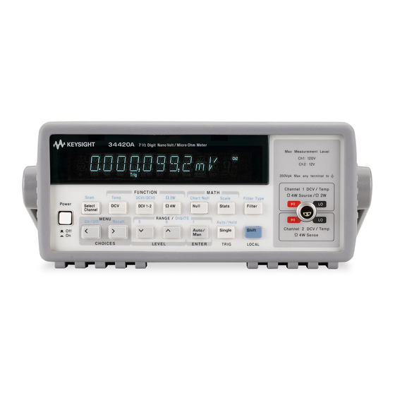
- Page 3 The 34420A is a 7 digit, high performance nanovolt, micro-ohm 1 /2 meter. Its combination of bench-top and system features makes this meter a versatile solution for your testing requirements now and in the future. Convenient bench-top features Built-in math operations including thermistor, thermocouple and RTD temperature measurements Two channel input allows ratio and difference functions for voltage measurements...
- Page 4 The Front-Panel at a Glance 1 Input channel select 5 Menu operation keys 2 Measurement function keys 6 Range/number of digits displayed keys 3 Math operation keys 7 Single trigger/autotrigger/auto hold key 4 Filter select key 8 Shift / local key...
- Page 5 The Front-Panel Menu at a Glance The menu is organized in a top-down tree structure with three levels. To turn on menu press: To move left/right To move up/down To enter a command press: A: MEASurement MENU Ø Ø Ø Ø...
- Page 6 Display Annunciators Turns on during a measurement. Meter is addressed to listen or talk over the HP-IB interface. Adrs Meter is in remote mode (using remote interface). Meter is using manual ranging (autorange is disabled). Meter is waiting for a single trigger or external trigger. Trig Offset compensation is turned off.
-
Page 7: The Rear Panel At A Glance
The Rear Panel at a Glance 1 Chassis ground 5 Voltmeter complete output terminal 2 Power-line fuse-holder assembly 6 External trigger input terminal 3 Power-line voltage setting 7 GPIB (IEEE-488) interface connector 4 Chart recorder output terminal 8 RS-232 interface connector (Analog out) Use the front-panel Input / Output Menu to: Select the GPIB or RS-232 interface... -
Page 8: In This Book
Specifications Chapter 8 lists the meter’s specifications and describes how to interpret these specifications. If you have questions relating to the operation of the meter, call 1-800-452-4844 in the United States, or contact your nearest Agilent Technologies Sales Office. -
Page 9: Table Of Contents
Contents Chapter 1 Quick Start To Prepare the Meter For Use 13 If the Meter Does Not Turn On 14 To Adjust the Carrying Handle 16 To Make Input Connections 17 To Measure Voltage 19 To Measure Resistance 20 To Measure Temperature With Thermistors 21 To Measure Temperature With RTDs 21 To Measure Temperature With Thermocouples 22 To Select a Range 23... - Page 10 Contents Chapter 3 Features and Functions (continued) Math Operations 74 Null (Relative) Operation 77 Reading Hold 79 Triggering 80 Trigger Source Choices 82 The Wait-for-Trigger State 85 Halting a Measurement in Progress 85 Number of Samples 86 Number of Triggers 86 Trigger Delay 87 Automatic Trigger Delays 89 System-Related Operations 90...
- Page 11 Contents Chapter 4 Remote Interface Reference (continued) Null (Relative) Commands 145 Input Filter Commands 146 Math Operation Commands 148 Statistics operation commands (AVERage) 149 Scale operation commands 150 Triggering 151 The Wait-for-Trigger State 153 Triggering Commands 154 Chart Output (Analog Out) Commands 156 System-Related Commands 157 The SCPI Status Model 159 What is an Event Register? 159...
- Page 12 Contents Chapter 5 Error Messages Execution Errors 201 Self-Test Errors 208 Calibration Errors 210 Chapter 6 ApplicationPrograms HP BASIC Language Programs 215 GPIB HP BASIC / HP-IB Program Example 1 215 GPIB HP BASIC / HP-IB Program Example 2 216 GPIB GPIB HP BASIC / HP-IB Program Example 3 218...
-
Page 13: Chapter 1 Quick Start
Quick Start... -
Page 14: Quick Start
Quick Start This chapter helps you prepare the meter for use and contains exercises designed to get you started with the meter, its menus, and the front panel. The front panel has two rows of keys to select various functions and operations. -
Page 15: To Prepare The Meter For Use
The following steps help you verify that the meter is ready for use. Check the list of supplied items. Verify that you have received the following items with your meter. If any Agilent Technologies Sales Office. item is missing, contact your nearest Hewlett-Packard Sales Office. One low thermal input cable. -
Page 16: If The Meter Does Not Turn On
Chapter 1 Quick Start If the Meter Does Not Turn On If the Meter Does Not Turn On Use the following steps to help solve problems you might experience when turning on the meter. If you need more help, see the Service Guide Agilent for service. - Page 17 Chapter 1 Quick Start If the Meter Does Not Turn On 1 Remove the power cord. Remove 2 Install the fuse. Remove the the fuse holder assembly from the rear line-voltage selector from the assembly. 250 mAT fuse (250V) 3 Rotate the line-voltage selector until 4 Replace the fuse-holder assembly in the the correct voltage appears in the window.
-
Page 18: To Adjust The Carrying Handle
Chapter 1 Quick Start To Adjust the Carrying Handle To Adjust the Carrying Handle To adjust the position, grasp the handle by the sides and pull outward. Then, rotate the handle to the desired position. Carrying Position Bench-top viewing positions... -
Page 19: To Make Input Connections
WHITE The connector and cable are an integral part of the measurement system. For the highest accuracy, use the copper cable and connectors supplied Agilent Technologies. by Hewlett-Packard. The conductors may require occasional cleaning to remove oxides. Cleaning the conductors is described on page 271. - Page 20 Chapter 1 Quick Start To Make Input Connections Using a Custom Cable Channel 1 – Source + Source – 4-Wire Source and Sense + Source and Sense – 2-Wire Thermistor Source and Sense + Source and Sense – Earth Ground (shell) Channel 2 –...
-
Page 21: To Measure Voltage
Chapter 1 Quick Start To Measure Voltage To Measure Voltage Channel 1 Ranges: 1 mV, 10 mV, 100 mV, 1 V, 10 V, 100 V Maximum resolution: 0.1 nV (on 1 mV range) Channel 2 Ranges: 1 mV, 10 mV, 100 mV, 1 V, 10 V Maximum resolution: 0.1 nV (on 1 mV range) Independent NULL for each channel Channel 1 LO to Channel 2 LO isolated to 150 Vpeak. -
Page 22: To Measure Resistance
Chapter 1 Quick Start To Measure Resistance To Measure Resistance , 1 k , 10 k , 100 k , 1 M Ranges: 1 , 10 , 100 Maximum resolution: 0.1 (on 1 ohm range) See also Resistance Measurements on page 68. (SOURCE) GREEN 4-WIRE... -
Page 23: To Measure Temperature With Thermistors
Chapter 1 Quick Start To Measure Temperature With Thermistors To Measure Temperature With Thermistors Thermistor type: 5 k BLACK GREEN OPEN WHITE To Measure Temperature With RTDs 4-wire, type: = .00385 (DIN/IEC 751) or = .00391 = 4.9 to 2.1 k (SOURCE) GREEN (SENSE) -
Page 24: To Measure Temperature With Thermocouples
Chapter 1 Quick Start To Measure Temperature With Thermocouples To Measure Temperature With Thermocouples Thermocouple types: B, E, J, K, N, R, S, T Reference: external thermistor, external fixed value, or internal thermistor. Channel 2 only. ISOTHERMAL BLOCK REFERENCE BLACK THERMISTOR GREEN EXTERNAL... -
Page 25: To Select A Range
Chapter 1 Quick Start To Select a Range To Select a Range You can let the meter automatically select the range using autoranging or you can select a fixed range using manual ranging. Toggles between autoranging and manual ranging Selects a higher range and disables autoranging Man annunciator is on when Selects a lower range... -
Page 26: To Set The Number Of Digits
Chapter 1 Quick Start To Set the Number of Digits To Set the Number of Digits You can set the display to show 4 , or 7 digits. In this book, the most significant digit (leftmost on the display) is referred to as the “... -
Page 27: To Set The Integration Time
Chapter 1 Quick Start To Set the Integration Time To Set the Integration Time Integration time is specified in Number of Power Line Cycles (NPLC). You can set the NPLC to 0.02, 0.2, 1, 2, 10, 20, 100, or 200. You can set the integration time to one of three fixed values by choosing the number of digits displayed, see page 24. -
Page 28: Front-Panel Display Formats
Chapter 1 Quick Start Front-Panel Display Formats Front-Panel Display Formats Negative sign or blank (positive) "1/2" digit (0 or 1) H.DDD,DDD,D EFF Numeric Digits Exponent (m,k,M) Measurement units Front-panel display format. 6 digits This is the 1 V range, 1.021,651 digits are displayed. -
Page 29: To Rack Mount The Meter
Chapter 1 Quick Start To Rack Mount the Meter To Rack Mount the Meter You can mount the meter in a standard 19-inch rack cabinet using one of three optional kits available. Instructions and mounting hardware are included with each rack-mounting kit. Any System II instrument of the same size can be rack-mounted beside the 34420A meter. - Page 30 Chapter 1 Quick Start To Rack Mount the Meter To rack mount a single instrument, order adapter kit 5063-9240. To rack mount two instruments side-by-side, order lock-link kit 5061-9694 and flange kit 5063-9212. To install one or two instruments in a sliding support shelf, order shelf 5063-9255, and slide kit 1494-0015 (for a single instrument, also order filler panel 5002-3999).
- Page 31 Front-Panel Operation...
- Page 32 Front-Panel Operation This chapter assumes you are familiar with the meter and menu operations. You should also understand how to make connections for the various types of measurements. If you are not familiar with this information, please read chapter 1, "Quick Start", starting on page 11. This chapter does not give a detailed description of every front-panel key or menu operation.
-
Page 33: Chapter 2 Front-Panel Operation Front-Panel Menu Reference
Chapter 2 Front-Panel Operation Front-Panel Menu Reference Front-Panel Menu Reference A: MEASurement MENU Ø Ø Ø Ø Ø 1: DIG FILTER 2: INTEGRATE 3: OCOMP 4: LOW POWER 5: LOW VOLT 6: LoV LIMIT Selects the digital filter speed. Can be set to FAST, MEDIUM, or SLOW. 1: DIG FILTER Sets the measurement integration time. - Page 34 Chapter 2 Front-Panel Operation Front-Panel Menu Reference E: SYStem MENU Ø Ø Ø Ø Ø Ø 1: RDGS STORE 2: SAVED RDGS 3: ERROR 4: TEST 5: CHART OUT 6: CHART SPAN Ø Ø Ø Ø 7: CHART NULL 8: DISPLAY 9: COMMA 10: PRESET 11: REVISION...
-
Page 35: A Front-Panel Menu Tutorial
Chapter 2 Front-Panel Operation A Front-Panel Menu Tutorial A Front-Panel Menu Tutorial This section is a step-by-step tutorial which shows how to use the front-panel menu. We recommend that you spend a few minutes with this tutorial to get comfortable with the structure and operation of the menu. The menu is organized in a top-down tree structure with three levels (menus, commands, and parameters). - Page 36 Chapter 2 Front-Panel Operation A Front-Panel Menu Tutorial Messages Displayed During Menu Use TOP OF MENU -You pressed while on the menus level; this is the top level of the menu and you cannot go any higher. To turn off the menu, press (Menu On/Off).
- Page 37 Chapter 2 Front-Panel Operation A Front-Panel Menu Tutorial Menu Example 1 The following steps show you how to turn on the menu, move up or down between levels, move across the choices on each level, and turn off the menu. In this example, you will turn off the display comma separator.
- Page 38 Chapter 2 Front-Panel Operation A Front-Panel Menu Tutorial > > > > Move across to the COMMA command on the commands level. > > > > There are eleven command choices available in the SYS MENU. Each choice on this level has a number prefix for easy identification ( , etc.).
- Page 39 Chapter 2 Front-Panel Operation A Front-Panel Menu Tutorial Menu Example 2 The following exercise demonstrates how to use the menu recall feature as a shortcut to set the COMMA command back to its original setting. You must perform the steps in Menu Example 1 before you start this example.
- Page 40 Chapter 2 Front-Panel Operation A Front-Panel Menu Tutorial Menu Example 3 Some commands in the menu require that you enter a numeric parameter value. The following steps show you how to enter a number in the menu. For this example, you will set the null value for channel 1 to –30 millivolts.
- Page 41 Chapter 2 Front-Panel Operation A Front-Panel Menu Tutorial Move down to edit the parameter. NULL VALUE The null value should be 0.000000 V when you come to this point in the menu for the first time. For this example, you will first set the null value to –0.300000 volts.
- Page 42 Chapter 2 Front-Panel Operation A Front-Panel Menu Tutorial > > > > Move the flashing cursor over to the units location. > > > Notice that the units are flashing on the right side of the display. – 0.300,000,0 10 Decrease the displayed number by a factor of 10. Notice that the position of the decimal point changes and the displayed number increases by a factor of 10 and the mV annunciator is on.
-
Page 43: To Select An Input Channel
Chapter 2 Front-Panel Operation To Select an Input Channel To Select an Input Channel For voltage measurements, you have two independent input channels. DC Voltage Channel 1 BLACK GREEN Channel 2 DC Voltage WHITE TOGGLES MEASUREMENT CHANNEL (SCAN) ALTERNATING MEASUREMENT CHANNELS Channel Pressing toggles the display between Channel 1 and... -
Page 44: To Select A Range
Chapter 2 Front-Panel Operation To Select a Range To Select a Range You can let the meter automatically select the range using autoranging or you can select a fixed range using manual ranging. Toggles between autoranging and manual ranging Selects a higher range and disables autoranging Man annunciator is on when Selects a lower range... -
Page 45: To Set Or Change The Number Of Digits
Chapter 2 Front-Panel Operation To Set or Change the Number of Digits To Set or Change the Number of Digits You can set the display to show 4 , or 7 digits. In this book, the most significant digit (leftmost on the display) is referred to as the “... -
Page 46: To Set The Integration Time
Chapter 2 Front-Panel Operation To Set the Integration Time To Set the Integration Time Integration time is specified in Number of Power Line Cycles (NPLC). You can set the NPLC to 0.02, 0.2, 1, 2, 10, 20, 100, or 200. Also see "Integration Time"... -
Page 47: To Make Null (Relative) Measurements
Chapter 2 Front-Panel Operation To Make Null (Relative) Measurements To Make Null (Relative) Measurements Each null measurement, also called relative, is the difference between a stored null value and the input signal. See page 77. Enables null operation; Null annunciator is on when Press again to disable null operation is enabled Reading = measurement –... -
Page 48: To Store Minimum And Maximum Readings (Stats)
Chapter 2 Front-Panel Operation To Store Minimum and Maximum Readings (Stats) To Store Minimum and Maximum Readings (Stats) You can store the minimum and maximum readings during a series of measurements. The following discussion shows how to read the minimum, maximum, average, peak-to-peak, standard deviation, and reading count. -
Page 49: To Trigger The Meter
Chapter 2 Front-Panel Operation To Trigger the Meter To Trigger the Meter You can trigger the meter from the front panel using single trigger or autotrigger. Toggles between autotrigger Trig annunciator is on when the meter and reading hold is waiting for single trigger (autotrigger disabled) Enables single trigger (sample) annunciator is on... -
Page 50: To Use Reading Hold
Chapter 2 Front-Panel Operation To Use Reading Hold To Use Reading Hold The reading hold feature allows you to capture and hold a stable reading on the display. When a stable reading is detected, the meter emits a beep and holds the value on the display. Toggles between autotrigger (sample) annunciator is on and reading hold... -
Page 51: To Make Voltage Ratio And Difference Measurements
Chapter 2 Front-Panel Operation To Make Voltage Ratio and Difference Measurements To Make Voltage Ratio and Difference Measurements To calculate a voltage ratio, the meter measures the voltages applied to the Channel 1 input terminals and Channel 2 input terminals. The calculation is as follows: Difference = ((Ch 1 voltage Ch 1 Null ) -
Page 52: To Use Reading Memory
Chapter 2 Front-Panel Operation To Use Reading Memory To Use Reading Memory The meter can store up to 1024 readings in internal memory. The following steps demonstrate how to store readings and retrieve them. Select the function. Select any measurement function. You can change the function at any time during reading memory. - Page 53 Chapter 2 Front-Panel Operation To Use Reading Memory > Move down a level and then across to the “ON” choice. Auto/Man Save the change and exit the menu. ENTER Notice that the Mem (memory) annunciator turns on to indicate that the meter is ready to store readings.
- Page 54 Chapter 2 Front-Panel Operation To Use Reading Memory 10 Move down a level to view the first stored reading. Reading memory is automatically turned off when you go to the “parameter” level in the menu. The first reading displayed is the first reading that was stored (FIFO). If no readings are stored in memory, “EMPTY”...
- Page 55 Features and Functions...
-
Page 56: Features And Functions
Features and Functions You will find that this chapter makes it easy to look up all the details about a particular feature of the meter. Whether you are operating the meter from the front panel or from the remote interface, this chapter will be useful. -
Page 57: Chapter 3 Features And Functions General Measurement Configuration
Chapter 3 Features and Functions General Measurement Configuration General Measurement Configuration This section contains information to help you configure the meter for making measurements. You may never have to change any of the measurement parameters discussed here, yet they are provided to give you the flexibility you might need. - Page 58 Chapter 3 Features and Functions General Measurement Configuration Shift Filter Front Panel operation: Press and scroll to one of DIGITAL, ANALOG, or ANA + DIG . Press Enter to enable the Filter filter type. Press the key to turn the filter on or off. To set the digital filter averaging, use the MEASurement menu 1: DIG FILTER command.
- Page 59 Chapter 3 Features and Functions General Measurement Configuration Digital Filter The digital filter is a moving average (boxcar) filter. Equal weighting is applied to all readings to calculate the displayed reading. Three digital filters are available: SLOW (average last 100 readings), MEDIUM (average last 50 readings), or FAST (average last 10 readings) When the digital filter is enabled, the ‘Filt’...
-
Page 60: Integration Time
Chapter 3 Features and Functions General Measurement Configuration Integration Time Integration time is the period during which the meter’s analog-to-digital (A/D) converter samples the input signal for a measurement. Integration time affects the measurement resolution (for better resolution, use a longer integration time), and measurement speed (for faster measurements, use a shorter integration time). - Page 61 Chapter 3 Features and Functions General Measurement Configuration Front Panel operation: Integration time can be set indirectly when you select the number of digits (See page 43). You can also set the integration time in the MEASurement menu with the 2: INTEGRATE command. Remote operation: Refer to the table on page 129.
-
Page 62: Reducing Measurement Noise
Chapter 3 Features and Functions General Measurement Configuration Reducing Measurement Noise At high resolutions and low measurement levels, measurement noise can become an important factor in the accuracy of your measurements. One possible source of measurement noise is the wiring and cabling in the test setup. - Page 63 Chapter 3 Features and Functions General Measurement Configuration 30 minute measurement, ±0.5° C, zero input, rms noise (typical) nV rms Noise Equivalent NPLC Approximate Reading Rate Readings per minute Readings per second Minutes per reading Front Panel operation: Integration time can be set indirectly when you select the number of digits (See page 43).
-
Page 64: Number Of Digits Displayed
Chapter 3 Features and Functions General Measurement Configuration Number of Digits Displayed Front Panel operation only. See also “Integration Time,” on page 58. You can set the number of digits shown in the display to 4, 5, 6, or 7 full digits, plus a “... - Page 65 Chapter 3 Features and Functions General Measurement Configuration 7 digits This is the 1 ohm range, 0.003,256,4 digits are displayed. " " digit 6 digits This is the 1 mV range, 0.216,569 digits are displayed. " " digit 5 digits This is the 100 mV range, 045.231 digits are displayed.
-
Page 66: Ranging
Chapter 3 Features and Functions General Measurement Configuration Ranging You can let the meter automatically select the range using autoranging or you can select a fixed range using manual ranging. Autoranging is convenient because the meter automatically selects the appropriate range for each measurement. -
Page 67: Overload Detection
Chapter 3 Features and Functions General Measurement Configuration Overload Detection The 34420A uses both an analog and digital method to generate an overload condition and display the OVLD message. An understanding of the cause of the overload can help you make more accurate measurements. -
Page 68: Voltage Measurement Configuration
Chapter 3 Features and Functions Voltage Measurement Configuration Voltage Measurement Configuration Input Channels The meter has two independent input channels for measuring dc Volts. You can make measurements on either or both channels, measure the difference between the channels, or measure the ratio between the channels. - Page 69 Chapter 3 Features and Functions Voltage Measurement Configuration Remote operation: The CONFigure and MEASure subsystems use an optional parameter to specify the input channel as either 1 or 2: CONF:VOLT:DC DEF, DEF,(@FRONTl) Channel 1 operation CONF:VOLT:DC DEF, DEF,(@FRONT2) Channel 2 operation The SENSe subsystem uses a keyword modification to indicate the channel: SENS1:VOLT:DC:RANG:AUTO...
-
Page 70: Resistance Measurement Configuration
Chapter 3 Features and Functions Resistance Measurement Configuration Resistance Measurement Configuration The meter can make 2-wire or 4-wire ohms measurements. The meter can compensate for voltages in the resistive circuit being measured using offset compensation. You can also choose to either limit the power applied or limit the open circuit voltage applied during a resistance measurement. - Page 71 Chapter 3 Features and Functions Resistance Measurement Configuration Offset Compensated Measurements Offset compensation removes the effect of any voltages in the circuit being measured. The technique involves taking two measurements, one with the current source turned on, and one with the current source turned off and computing the difference.
- Page 72 Chapter 3 Features and Functions Resistance Measurement Configuration Voltage Limited Measurements Voltage limited resistance measurements clamp the open circuit voltage to predefined limits. Voltage limits apply only to 4-wire ohms measurements. Voltage limited resistance measurements are only available on the 10 and 100 ranges.
-
Page 73: Temperature Measurement Configuration
Chapter 3 Features and Functions Temperature Measurement Configuration Temperature Measurement Configuration This section contains information to help you configure the meter for making temperature measurements. To measure temperature, you will need a temperature transducer. Transducer descriptions and specific comments about their usage are given on page 263. The meter supports three general categories of transducer: RTD (Resistive Temperature Device) THERM (Thermistor) -
Page 74: Rtd Measurements
Chapter 3 Features and Functions Temperature Measurement Configuration RTD Measurements The meter supports RTDs with = 0.00385 (DIN/IEC 751) or ) must be in the range = 0.00391. The nominal value of the RTD (R of 4.9 to 2.1 k . RTD Connections are shown on page 21. The meter makes a 4-wire measurement for RTD’s. -
Page 75: Thermocouple Measurements
Chapter 3 Features and Functions Temperature Measurement Configuration Thermocouple Measurements The thermocouple must be connected to the Channel 2 inputs. Be sure to observe the correct polarity. Thermocouple connections are shown on page 22. Thermocouple measurements require a reference junction temperature. -
Page 76: Math Operations
Chapter 3 Features and Functions Math Operations Math Operations There are two math operations available, only one of which can be enabled at a time. You can choose to either scale the readings as they are taken, or keep statistics on a group of readings. The selected math operation remains in effect until you disable it, change functions, turn off the power, or perform a remote interface reset. - Page 77 Chapter 3 Features and Functions Math Operations Statistics After you enable statistics, the first reading that the meter takes is stored as both the minimum and maximum value. The minimum is replaced with any subsequent value that is less. The maximum is replaced with any subsequent value that is greater.
- Page 78 Chapter 3 Features and Functions Math Operations Remote operation: the math operations and registers are controlled using math operation commands. First, select the math operation you want to use CALCulate:FUNCtion AVERage Then, enable the selected math function by turning the math state on: CALCulate:STATe ON When you have finished collecting readings, obtain the desired statistics: CALCulate:AVERage...
-
Page 79: Null (Relative) Operation
Chapter 3 Features and Functions Null (Relative) Operation Null (Relative) Operation When making null measurements, also called relative, each reading is the difference between the input signal and a stored null value. You could, for example, make a more accurate two-wire ohms measurement by Null shorting the test leads and pressing to remove the test lead... - Page 80 Chapter 3 Features and Functions Null (Relative) Operation Front-panel operation: After enabling null, you can edit the stored Shift > null value by pressing (Menu Recall). Any previously stored value is replaced with the new value. Turning on the menu does not disable the null operation;...
-
Page 81: Reading Hold
Chapter 3 Features and Functions Reading Hold Reading Hold The reading hold feature allows you to capture and hold a stable reading on the front-panel display. This is especially useful in situations where you want to take a reading, remove the test probes, and have the reading remain on the display. -
Page 82: Triggering
Chapter 3 Features and Functions Triggering Triggering The meter’s triggering system allows you to generate triggers either manually or automatically, take multiple readings per trigger, and insert a delay before each reading. Normally, the meter will take one reading each time it receives a trigger, but you can specify multiple readings (up to 50,000) per trigger. - Page 83 Chapter 3 Features and Functions Triggering Initiate Triggering MEASure? READ? Idle INITiate State Trigger Source TRIGger:SOURce IMMediate TRIGger:SOURce EXTernal Wait-for- TRIGger:SOURce BUS Trigger front-panel "Single" key State Trigger Delay TRIGger:DELay Delay Sample (*) Annunciator Measurement Sample Sample Trigger Count >1 Count >1 Triggering the meter is a multi-step process.
-
Page 84: Trigger Source Choices
Chapter 3 Features and Functions Triggering Trigger Source Choices You must specify the source from which the meter will accept a trigger. The trigger source is stored in volatile memory; the source is set to autotrigger (front panel) or immediate (remote interface) when power has been off or after a remote interface reset. - Page 85 Chapter 3 Features and Functions Triggering External Triggering In the external trigger mode, the meter will accept a hardware trigger applied to the Ext Trig terminal. The meter takes one reading, or the specified number of readings (sample count), each time Ext Trig receives a low-true pulse. See also “External Trigger Terminal,”...
- Page 86 Chapter 3 Features and Functions Triggering Internal Triggering In the internal trigger mode (remote interface only), the trigger signal is always present. When you place the meter in the wait-for-trigger state, the trigger is issued immediately. This is the power-on trigger source for remote interface operation. To select the internal trigger source, send the following command.
-
Page 87: The Wait-For-Trigger State
Chapter 3 Features and Functions Triggering The Wait-for-Trigger State After you have configured the meter and selected a trigger source, you must place the meter in the wait-for-trigger state. A trigger will not be accepted until the meter is in this state. If a trigger signal is present, and if meter is in the “wait-for-trigger”... -
Page 88: Number Of Samples
Chapter 3 Features and Functions Triggering Number of Samples Normally, the meter takes one reading (or sample) each time it receives a trigger from the selected trigger source (if the meter is in the wait-for-trigger state). You can, however, instruct the meter to take multiple readings for each trigger received. -
Page 89: Trigger Delay
Chapter 3 Features and Functions Triggering Trigger Delay You can insert a delay between the trigger signal and each sample that follows. This may be useful in applications where you want to allow the input to settle before taking a reading, or for pacing a burst of readings. If you do not specify a trigger delay, the meter automatically selects a delay for you. - Page 90 Chapter 3 Features and Functions Triggering Front Panel operation (continued) To set the delay to 0 seconds, select the “parameter” level of the TRIG DELAY command. Move the flashing cursor to the “units” location on the right side of the display. Press until Enter ZERO DELAY is reached, then press...
-
Page 91: Automatic Trigger Delays
Chapter 3 Features and Functions Triggering Automatic Trigger Delays If you do not specify a trigger delay, the meter selects an automatic delay for you. The delay is determined by function, range, and integration time. DC voltage : < ³ Range NPLC NPLC... -
Page 92: System-Related Operations
Chapter 3 Features and Functions System-Related Operations System-Related Operations This section gives information on topics such as reading memory, errors, self-test, and front-panel display control. This information is not directly related to making measurements but is an important part of operating the meter. - Page 93 Chapter 3 Features and Functions System-Related Operations Front-panel operation: enable readings storage under the 1: RDGS STORE command in the SYStem menu. The ‘Mem’ annunciator lights in the display. Recall the stored readings under the 2: SAVED RDGS command in the SYStem menu.
-
Page 94: Error Conditions
Chapter 3 Features and Functions System-Related Operations Error Conditions ERROR’ When the front-panel ‘ annunciator turns on, one or more command syntax or hardware errors have been detected. A record of up to 20 errors is stored in the meter’s error queue. See chapter 5, “Error Messages,”... -
Page 95: Self-Test
Chapter 3 Features and Functions System-Related Operations Self-Test A power-on self-test occurs automatically when you turn on the multimeter. This limited test assures you that the meter is operational. This self-test does not perform the extensive set of tests that are included as part of the complete self-test described below. -
Page 96: Display Control
Chapter 3 Features and Functions System-Related Operations Display Control To speed up your measurement rate, or for security reasons, you may want to turn off the front-panel display. From the remote interface, you can also display a 11-character message on the front panel. See page 43 for information about the number of digits displayed. -
Page 97: Comma Separators
Chapter 3 Features and Functions System-Related Operations Comma Separators The meter can display readings on the front panel with or without a comma separator. This feature is available only from the front panel. See “Menu Example 1” on page 35. 08.241,53 08.24153 With comma separator... -
Page 98: Scpi Language Version
Chapter 3 Features and Functions System-Related Operations SCPI Language Version The meter complies with the rules and regulations of the present version (Standard Commands for Programmable Instruments). You can SCPI determine the version with which the meter is in compliance by SCPI sending a command from the remote interface. -
Page 99: Voltmeter Complete Terminal
Chapter 3 Features and Functions Voltmeter Complete Terminal Voltmeter Complete Terminal The rear-panel VM Comp (voltmeter complete) terminal provides a low-true pulse after the completion of each measurement. Voltmeter complete and external trigger (see below) implement a standard hardware handshake sequence between measurement and switching devices. -
Page 100: Chart Output (Analog Output)
Chapter 3 Features and Functions Chart Output (Analog Output) Chart Output (Analog Output) You can use the Chart Output (Analog Output) connector on the rear panel to run a strip chart recorder or similar instrument. The connector provides an output voltage proportional to the measured voltage. The output can range from –3.00 V to +3.00 V. - Page 101 Chapter 3 Features and Functions Chart Output (Analog Output) 2) To set the chart output voltage to ±3.0 V to correspond to an input temperature range of 5° C to 45° C with a mid temperature of 25° C (chart output is 0 V at 25° C). chart null ) chart null span...
-
Page 102: Chart Rollover
Chapter 3 Features and Functions Chart Output (Analog Output) Chart Rollover To prevent the loss of data, the chart output will "rollover" if a measurement would cause the chart output to exceed the limits (± 3 V). This feature is especially useful with strip chart recorders. Rollover can be used to increase the resolution of the chart since smaller values of span can be specified. -
Page 103: Remote Interface Configuration
Chapter 3 Features and Functions Remote Interface Configuration Remote Interface Configuration This section gives information on configuring the remote interface. For programming information, see Chapter 4, “Remote Interface Reference,” starting on page 115. Remote Interface Selection GPIB The meter is shipped with both a ) interface and an HP-IB IEEE-488... -
Page 104: Gpib
Chapter 3 Features and Functions Remote Interface Configuration GPIB HP-IB Address GPIB Each device on the ) interface must have a unique HP-IB IEEE-488 address. You can set the meter’s address to any value between 0 and 31. The address is set to “22” when the meter is shipped from the factory. GPIB address is displayed when you turn on the meter. -
Page 105: Baud Rate Selection
Chapter 3 Features and Functions Remote Interface Configuration Baud Rate Selection ( RS-232 You can select one of six baud rates for operation. The rate is set RS-232 to 9600 baud when the meter is shipped from the factory. Select one of the following: 300, 600, 1200, 2400, 4800, or 9600 baud (factory setting). -
Page 106: Parity Selection
Chapter 3 Features and Functions Remote Interface Configuration Parity Selection ( RS-232 You can select the parity for operation. The meter is configured for RS-232 even parity with 7 data bits when shipped from the factory. Select one of the following: None (8 data bits), Even (7 data bits), or Odd (7 data bits). -
Page 107: Programming Language Selection
Chapter 3 Features and Functions Remote Interface Configuration Programming Language Selection You can select one of two languages to program the meter from the selected remote interface. The programming language is SCPI when the meter is shipped from the factory. Select one of the following: SCPI or 181 (Keithley). -
Page 108: Connection To A Terminal Or Printer (Rs-232)
Chapter 3 Features and Functions Remote Interface Configuration Connection to a Terminal or Printer (RS-232) The RS-232 connector on the meter’s rear panel is a 9-pin connector (DB-9, male connector). You can connect the meter to any terminal or printer with a properly configured DTE connector (DB-25). You can use a standard serial interface cable and the 34399A Adapter Kit to make connections. -
Page 109: Calibration
Chapter 3 Features and Functions Calibration Calibration This section gives a brief introduction to the calibration features of the meter. For a more detailed discussion of the calibration procedures, see Chapter 4 in the Service Guide. Calibration Security This feature allows you to enter a security code to prevent accidental or unauthorized calibrations of the meter. - Page 110 Chapter 3 Features and Functions Calibration To Unsecure for Calibration You can unsecure the meter for calibration either from the front panel or remote interface. The meter is secured when shipped from the factory, and the security code is set to “HP034420”.
- Page 111 Chapter 3 Features and Functions Calibration To Secure Against Calibration You can secure the meter against calibration either from the front panel or remote interface. The meter is secured when shipped from the factory, and the security code is set to “HP034420”.
-
Page 112: Calibration Count
Chapter 3 Features and Functions Calibration To Change the Security Code To change the security code, you must first unsecure the meter, and then enter a new code. Make sure you have read the security code rules on page 107 before attempting to secure the meter. -
Page 113: Calibration Message
Chapter 3 Features and Functions Calibration Calibration Message You can use the calibration message feature to record calibration information about your meter. For example, you can store such information as the last calibration date, the next calibration due date, the meter’s serial number, or even the name and phone number of the person to contact for a new calibration. -
Page 114: Defaults, Power-On And Reset States
Chapter 3 Features and Functions Defaults, Power-On and Reset States Defaults, Power-On and Reset States The meter stores settings in either volatile or non-volatile memory. Settings stored in volatile memory are returned to default settings at power-on or after a remote reset. Settings stored in non-volatile memory are not changed by power-on or a remote reset (*RST), CONFigure, or MEASure command. - Page 115 Chapter 3 Features and Functions Defaults, Power-On and Reset States Non-volatile memory settings can be returned to their factory defaults. Front Panel operation: return the settings to factory defaults under the 11: PRESET command in the SYStem menu. Remote operation: use the SYStem:PRESet command to return the meter to the factory defaults.
- Page 116 Chapter 3 Features and Functions Defaults, Power-On and Reset States Independent vs. common settings: Some settings are independent to the channel or function being used and some are common to multiple channels or functions: Voltage Resistance Temperature Channel 1 Channel 2 2-Wire 4-Wire Null (On/Off)
-
Page 117: Chapter 4 Remote Interface Reference
Remote Interface Reference... - Page 118 Remote Interface Reference This chapter is divided into the following sections: Command Summary, page 117 Simplified Programming Sequence, page 126 The MEASure? and CONFigure Commands, page 134 Setting the Function, Range, and Resolution, page 137 Selecting the Input Channel, page 140 Special Resistance Measurement Commands, page 141 Temperature Measurement Commands, page 142 Null (Relative) Commands, page 145...
-
Page 119: Command Summary
Chapter 4 Remote Interface Reference Command Summary Command Summary This section summarizes the (Standard Commands for SCPI Programmable Instruments) commands available to program the meter. Refer to the later sections in this chapter for more complete details on each command. Throughout this manual, the following conventions are used for SCPI command syntax. - Page 120 Chapter 4 Remote Interface Reference Command Summary Voltage Measurement Configuration Commands MEASure [:VOLTage][:DC]? [{< range > | AUTO | MIN | MAX | DEF}][,{< resolution > | MIN | MAX | DEF}][,(@< channel >)] [:VOLTage][:DC]:RATio? [{< range > | AUTO | MIN | MAX | DEF}][,{< resolution > | MIN | MAX | DEF}] [:VOLTage][:DC]:DIFFerence? [{<...
- Page 121 Chapter 4 Remote Interface Reference Command Summary Resistance Measurement Configuration Commands MEASure :FRESistance? [{< range > | AUTO | MIN | MAX | DEF}][,{< resolution > | MIN | MAX | DEF}] :RESistance? [{< range > | AUTO | MIN | MAX | DEF}][,{< resolution > | MIN | MAX | DEF}] CONFigure :FRESistance | :RESistance [{<...
- Page 122 Chapter 4 Remote Interface Reference Command Summary Temperature Measurement Configuration Commands MEASure :TEMPerature? [{TC | THER | FRTD | DEF}][,{< type > | DEF}][, 1, {< resolution > | MAX | MIN | DEF}] CONFigure :TEMPerature [{TC | THER | FRTD | DEF}][,{< type > | DEF}][, 1, {< resolution > | MAX | MIN | DEF}] [SENSe:] FUNCtion "TEMPerature"...
- Page 123 Chapter 4 Remote Interface Reference Command Summary General Measurement Configuration Commands CONFigure? [SENSe:]NULL [{OFF | ON | ONCE}] INPut:FILTer :STATe {OFF | ON} :STATe? :TYPE {ANALog | DIGital | BOTH} :TYPE? :DIGital:RESPonse {SLOW | MEDium | FAST} :DIGital:RESPonse? :DIGital:PRECharge:AUTO {ON | OFF} :DIGItal:PRECharge:AUTO? ROUTe:TERMinals {FRONt | FRONt1 | FRONt2} ROUTe:TERMinals?
- Page 124 Chapter 4 Remote Interface Reference Command Summary Triggering Commands INITiate READ? TRIGger :SOURce {BUS | IMMediate | EXTernal} :SOURce? TRIGger :DELay {< seconds > | MIN | MAX} :DELay? [MIN | MAX] :DELay:AUTO {OFF | ON} :DELay:AUTO? TRIGger :COUNt {< value > | MIN | MAX | INFinity} :COUNt? [MIN | MAX] SAMPle :COUNt {<...
- Page 125 Chapter 4 Remote Interface Reference Command Summary System-Related Commands (continued) DISPlay[:STATe] {OFF | ON} DISPlay? DISPlay :TEXT < quoted string > :TEXT? :TEXT:CLEar SYSTem:ERRor? SYSTem:PRESet SYSTem:VERSion? *RST *TST? *IDN? Status Reporting Commands SYSTem:ERRor? STATus :OPERation:CONDition? :OPERation:ENABle < enable value > :OPERation:ENABle? :OPERation[:EVENt]? :QUEStionable:CONDition?
- Page 126 Chapter 4 Remote Interface Reference Command Summary Calibration Commands CALibration? CALibration:COUNt? CALibration :ICURrent? CALibration :OUTPut {ZERO | GAIN} :OUTPut? CALibration :SECure:CODE < new code > :SECure:STATe {OFF | ON} [,< code >] :SECure:STATe? CALibration :STRing < quoted string > :STRing? CALibration :VALue <...
- Page 127 Chapter 4 Remote Interface Reference Command Summary IEEE-488.2 Common Commands *CLS *ESE < enable value > *ESE? *ESR? *IDN? *OPC *OPC? *PSC {0 | 1} *PSC? *RST *SRE < enable value > *SRE? *STB? *TRG *TST? *WAI...
-
Page 128: Simplified Programming Sequence
Chapter 4 Remote Interface Reference Simplified Programming Sequence Simplified Programming Sequence You can program the meter to take measurements from the remote interface using the following seven-step sequence. Throughout this manual, the following conventions are used for SCPI command syntax. Square brackets ( [] ) indicate optional keywords or parameters. - Page 129 Chapter 4 Remote Interface Reference Simplified Programming Sequence MEASure? and CONFigure Defaults Setting SCPI Command System Defaults Used Input Channel ROUTe:TERMinals Channel 1 Digital Filter INPut:FILTer Digital Filter Precharge INPut:FILTer Last value set Analog Filter INPut:FILTer Common Trigger Source TRIGger:SOURce Immediate to all Trigger Delay...
-
Page 130: Using The Measure? Command
Chapter 4 Remote Interface Reference Simplified Programming Sequence Using the Command MEASure? The easiest way to program the meter for measurements is by using the MEASure? command. However, this command does not offer much flexibility. When you execute the command, the meter uses defaults for the requested configuration and immediately performs the measurement. -
Page 131: Using The Range And Resolution Parameters
Chapter 4 Remote Interface Reference Simplified Programming Sequence Using the range and resolution Parameters With the MEASure? and CONFigure commands, you can select the measurement function, range, and resolution all in one command. Use the range parameter to specify a fixed range larger than the expected value of the input signal. -
Page 132: Using The Read? Command
Chapter 4 Remote Interface Reference Simplified Programming Sequence Using the READ? Command The READ? command changes the state of the trigger system from the “idle” state to the “wait-for-trigger” state. Measurements will begin when the specified trigger conditions are satisfied following the receipt of the READ? command. -
Page 133: Using The Initiate And Fetch? Commands
Chapter 4 Remote Interface Reference Simplified Programming Sequence Using the INITiate and FETCh? Commands The INITiate and FETCh? commands provide the lowest level of control (with the most flexibility) of measurement triggering and reading retrieval. Use the INITiate command after you have configured the meter for the measurement. - Page 134 Chapter 4 Remote Interface Reference Simplified Programming Sequence MEASure? The following program segment shows how to use the MEASure? command to make a measurement. This example configures the meter for Example voltage measurements on channel 1 using autoranging on the input signal, automatically places the meter in the “wait-for-trigger”...
- Page 135 Chapter 4 Remote Interface Reference Simplified Programming Sequence CONFigure The following program segment is similar to the example above but it uses INITiate to place the meter in the “wait-for-trigger” state. The Example 2 INITiate command places the meter in the “wait-for-trigger” state, takes a reading when the Ext Trig terminal is pulsed, and sends the reading to the meter’s internal memory.
-
Page 136: The Measure? And Configure Commands
Chapter 4 Remote Interface Reference The MEASure? and CONFigure Commands The MEASure? and CONFigure Commands See also “General Measurement Configuration,” starting on page 55 in chapter 3. Both the MEASure? and CONFigure commands reset measurement parameters to defaults. See page 127. For the range parameter, MIN selects the lowest range for the selected function;... - Page 137 Chapter 4 Remote Interface Reference The MEASure? and CONFigure Commands MEASure[:VOLTage][:DC]:DIFFerence? [{< range > | AUTO | MIN | MAX | DEF}][,{< resolution > | MIN | MAX | DEF}] This command presets and makes a difference measurement with the specified range and resolution.
- Page 138 Chapter 4 Remote Interface Reference The MEASure? and CONFigure Commands CONFigure[:VOLTage][:DC]:DIFFerence [{< range > | AUTO | MIN | MAX | DEF}][,{< resolution > | MIN | MAX | DEF}] This command presets and configures the meter for difference measurements with the specified range and resolution. This command does not initiate the measurement.
-
Page 139: Setting The Function, Range, And Resolution
Chapter 4 Remote Interface Reference Setting the Function, Range, and Resolution Setting the Function, Range, and Resolution See also “General Measurement Configuration,” starting on page 55 in chapter 3. [SENSe:]FUNCtion "< function >" Select a measurement function. The function must be enclosed in quotes in the command string (for example, FUNC "VOLT:DC"). - Page 140 Chapter 4 Remote Interface Reference Setting the Function, Range, and Resolution [{SENSe1: | SENSe2:}]VOLTage[:DC]:RANGe:AUTO {OFF | ON} [SENSe:] FRESistance | RESistance :RANGe:AUTO {OFF | ON} This command disables or enables autoranging for the function. Autorange thresholds: Down range at <10% of range; Up range at >120% of range.
- Page 141 Chapter 4 Remote Interface Reference Setting the Function, Range, and Resolution [SENSe1: | SENSe2:]VOLTage[:DC]:NPLCycles {0.02 | 0.2 | 1 | 2 | 10 | 20 | 100 | 200 | MIN | MAX} [SENSe:] FRESistance | RESistance :NPLCycles {0.02 | 0.2 | 1 | 2 | 10 | 20 | 100 | 200 | MIN | MAX} [SENSe:]TEMPerature:NPLCycles {0.02 | 0.2 | 1 | 2 | 10 | 20 | 100 | 200 | MIN | MAX} This command selects the integration time in number of power line cycles for the present function (the default is 10 PLC).
-
Page 142: Selecting The Input Channel
Chapter 4 Remote Interface Reference Selecting the Input Channel Selecting the Input Channel The correct input channel is automatically selected for resistance and temperature measurement functions. For voltage measurements, you must select the input channel. The easiest, but least flexible, method to specify the input channel is by using the channel parameter in the MEASure? or CONFigure commands. -
Page 143: Special Resistance Measurement Commands
Chapter 4 Remote Interface Reference Special Resistance Measurement Commands Special Resistance Measurement Commands The following commands provide offset compensation and low power or voltage limited resistance measurement capability. [SENSe:] FRESistance | RESistance :OCOMpensated {OFF | ON} :OCOMpensated? This command enables or disables the offset compensated resistance measurements (see page 69). -
Page 144: Temperature Measurement Commands
Chapter 4 Remote Interface Reference Temperature Measurement Commands Temperature Measurement Commands See "Temperature Measurement Configuration" on page 71 in Chapter 3. The meter stores the last settings used for temperature measurements in non-volatile memory and uses these values as the default for future measurements. - Page 145 Chapter 4 Remote Interface Reference Temperature Measurement Commands [SENSe:]TEMPerature:TRANsducer:TYPE {TC | THER | FRTD | DEF} This command sets the type of temperature transducer to use for temperature measurements. Choose TC (thermocouples), THER (thermistors), or FRTD (four-wire RTD). DEF sets FRTD. [SENSe:]TEMPerature:TRANsducer:TYPE? This command queries for the current temperature measurement transducer type.
- Page 146 Chapter 4 Remote Interface Reference Temperature Measurement Commands [SENSe:]TEMPerature:TRANsducer:FRTD:TYPE {85 | 91} This command sets the four-wire RTD type. The alpha is entered as either 85 (for = .000385) or 91 (for = .000391). [SENSe:]TEMPerature:TRANsducer:FRTD:TYPE? This command queries for the type of RTD being used. Returns either +91 or +85.
-
Page 147: Null (Relative) Commands
Chapter 4 Remote Interface Reference Null (Relative) Commands Null (Relative) Commands The meter uses independant null values for channel 1 and channel 2 voltage measurements, resistance measurements, and temperature measurements. See page 77 in Chapter 3. [SENSe:] | SENSe1: | SENSe2 VOLTage[:DC]:NULL[:STATe] {OFF | ON} VOLTage[:DC]:NULL[:STATe]? VOLTage[:DC]:NULL:VALue {<... -
Page 148: Input Filter Commands
Chapter 4 Remote Interface Reference Input Filter Commands Input Filter Commands See also page 55 in Chapter 3. Using the input filters from the remote interface is not recommended. To use the filters with the remote interface be aware of the following: The digital filter is a moving average (boxcar) filter. - Page 149 Chapter 4 Remote Interface Reference Input Filter Commands INPut:FILTer :STATe {OFF | ON} :STATe? These commands enable or disable the filter state and query the filter state. INPut:FILTer :TYPE {ANALog | DIGital | BOTH} :TYPE? These commands set the filter type and query the filter type. BOTH enables the digital and analog filters.
-
Page 150: Math Operation Commands
Chapter 4 Remote Interface Reference Math Operation Commands Math Operation Commands See also “Math Operations,” starting on page 74 in chapter 3. There are two main math operations available; stats and scale, only one of which can be enabled at a time. Stats performs mathematical operations on a series of readings. -
Page 151: Statistics Operation Commands (Average)
Chapter 4 Remote Interface Reference Math Operation Commands Statistics operation commands (AVERage) You must have set CALC:FUNC AVER and CALC ON to use these commands. CALCulate:AVERage:MINimum? This command returns the minimum value found during a math average operation. The meter clears the value when math is turned on, when power has been off, or after a remote interface reset. -
Page 152: Scale Operation Commands
Chapter 4 Remote Interface Reference Math Operation Commands DATA:FEED RDG_STORE, {"CALCulate" | " "} This command selects whether readings taken using the INITiate command are stored in the meter’s internal memory (default) or not stored at all. In the default state (DATA:FEED RDG_STORE, "CALC"), up to 1024 readings are stored in memory when INITiate is executed. -
Page 153: Triggering
Chapter 4 Remote Interface Reference Triggering Triggering See also “Triggering,” starting on page 80 in chapter 3. The meter’s triggering system allows you to generate triggers either manually or automatically, take multiple readings per trigger, and insert a delay before each reading. Normally, the meter will take one reading each time it receives a trigger, but you can specify multiple readings (up First time SCPI users, to 50,000) per trigger. - Page 154 Chapter 4 Remote Interface Reference Triggering Initiate Triggering MEASure? READ? Idle INITiate State Trigger Source TRIGger:SOURce IMMediate TRIGger:SOURce EXTernal Wait-for- TRIGger:SOURce BUS Trigger front-panel "Single" key State Trigger Delay TRIGger:DELay Delay Sample (*) Annunciator Measurement Sample Sample Trigger Count >1 Count >1 Triggering the meter is a multi-step process.
-
Page 155: The Wait-For-Trigger State
Chapter 4 Remote Interface Reference Triggering The Wait-for-Trigger State After you have configured the meter and selected a trigger source, you must place the meter in the wait-for-trigger state. A trigger will not be accepted until the meter is in this state. If a trigger signal is present, and if the meter is in the “wait-for-trigger”... -
Page 156: Triggering Commands
Chapter 4 Remote Interface Reference Triggering Commands Triggering Commands See also “Triggering,” starting on page 80 in chapter 3. INITiate This command changes the state of the triggering system from the “idle” state to the “wait-for-trigger” state. Measurements will begin when the specified trigger conditions are satisfied after the INITiate command is received. - Page 157 Chapter 4 Remote Interface Reference Triggering Commands TRIGger:DELay {< seconds > | MIN | MAX} This command inserts a trigger delay between the trigger signal and each sample that follows. If you do not specify a trigger delay, the meter automatically selects a delay for you (see page 89).
-
Page 158: Chart Output (Analog Out) Commands
Chapter 4 Remote Interface Reference Chart Output (Analog Out) Commands Chart Output (Analog Out) Commands See also "Chart Output", starting on page 98 in chapter 3. OUTPut [:STATe] {OFF | ON} [:STATe]? These commands enable or disable the chart output (analog output) and query the output state. -
Page 159: System-Related Commands
Chapter 4 Remote Interface Reference System-Related Commands System-Related Commands See also “System-Related Operations,” starting on page 90 in chapter 3. FETCh? This command transfers readings stored in the meter’s internal memory by the INITiate command to the meter’s output buffer where you can read them into your bus controller. - Page 160 Chapter 4 Remote Interface Reference System-Related Commands SYSTem:ERRor? This command queries the meter’s error queue. Up to 20 errors can be stored in the queue. Errors are retrieved in first-in-first out ( ) order. FIFO Each error string may contain up to 80 characters. SYSTem:VERSion? This command queries the meter to determine the present version.
-
Page 161: The Scpi Status Model
Chapter 4 Remote Interface Reference The SCPI Status Model The SCPI Status Model instruments implement status registers in the same way. The SCPI status system records various instrument conditions in four register groups: the Status Byte register, the Standard Event register, The Operational Status register, and the Questionable Data register. -
Page 162: Scpi Status System
Chapter 4 Remote Interface Reference The SCPI Status Model SCPI Status System + See page 169 for information on the use of this bit. -
Page 163: The Status Byte
Chapter 4 Remote Interface Reference The SCPI Status Model The Status Byte The status byte summary register reports conditions from other status registers. Query data that is waiting in the meter’s output buffer is immediately reported through the “message available” bit (bit 4). Bits in the summary registers are not latched. -
Page 164: Using Service Request ( Srq ) And Serial Poll
Chapter 4 Remote Interface Reference The SCPI Status Model The status byte summary register is cleared when: You execute a *CLS (clear status) command. Querying the standard event and questionable data registers will clear only the respective bits in the summary register. The status byte enable register (request service) is cleared when: You turn on the power and you have previously configured the meter using the *PSC 1 command. -
Page 165: Using *Stb? To Read The Status Byte
Chapter 4 Remote Interface Reference The SCPI Status Model Using to Read the Status Byte *STB? The *STB? (status byte query) command is similar to a serial poll except it is processed like any other instrument command. The *STB? command returns the same result as an serial poll except that the IEEE-488... -
Page 166: How To Use The Message Available Bit
Chapter 4 Remote Interface Reference The SCPI Status Model How to Use the Message Available Bit ( You can use the status byte “message available” bit (bit 4) to determine when data becomes available to read into your bus controller. The meter sets bit 4 when the first reading trigger occurs (which can be TRIGger:SOURce:IMMediate). - Page 167 Chapter 4 Remote Interface Reference The SCPI Status Model The Standard Event Register The standard event register reports the following types of instrument events: power-on detected, command syntax errors, command execution errors, self-test or calibration errors, query errors, or when an *OPC command is executed. Any or all of these conditions can be reported in the standard event summary bit through the enable register.
- Page 168 Chapter 4 Remote Interface Reference The SCPI Status Model The standard event register is cleared when: You send a *CLS (clear status) command. You query the event register using the *ESR? (event status register) command. The standard event enable register is cleared when: You turn on the power and you have previously configured the meter using the *PSC 1 command.
- Page 169 Chapter 4 Remote Interface Reference The SCPI Status Model The Questionable Data Register The questionable data register provides information about the quality of the meter’s measurement results. Overload conditions can be reported in the questionable data summary bit through the enable register. You must write a decimal value using the STATus:QUEStionable:ENABle command to set the enable register mask.
- Page 170 Chapter 4 Remote Interface Reference The SCPI Status Model The questionable data event register is cleared when: You execute a *CLS (clear status) command. You query the event register using STATus:QUEStionable:EVENt?. The questionable data enable register is cleared when: You turn on the power (*PSC does not apply). You execute the STATus:PRESet command.
-
Page 171: The Operational Status And Condition Registers
Chapter 4 Remote Interface Reference The SCPI Status Model The Operational Status and Condition Registers The operation status register provides information about the operation of the meter. Bits in the operational status event register are latched from changes in the bits in the operational status condition register. The meter only uses a single bit (bit 8) in these registers. - Page 172 Chapter 4 Remote Interface Reference The SCPI Status Model Bit Definitions — Operational Status Register Decimal Value Definition Not Used Always set to 0 Filter Settled Digital filter is settled. Not Used Always set to 0. The operational status event register is cleared when: You execute a *CLS (clear status) command.
-
Page 173: Status Reporting Commands
Chapter 4 Remote Interface Reference Status Reporting Commands Status Reporting Commands SYSTem:ERRor? This command queries the meter’s error queue. Up to 20 errors can be stored in the queue. Errors are retrieved in first-in-first out ( ) order. FIFO Each error string may contain up to 80 characters. STATus:QUEStionable:CONDition? This command queries the questionable status condition register. - Page 174 Chapter 4 Remote Interface Reference Status Reporting Commands STATus:OPERation:EVENt? This command queries the Questionable Data event register. The meter returns a decimal value which corresponds to the binary-weighted sum of all bits set in the register. Only bit 8 (decimal 256) is used and latches the digital filter settled state of the condition register.
- Page 175 Chapter 4 Remote Interface Reference Status Reporting Commands *PSC {0 | 1} (Power-on status clear.) This command clears the Status Byte and Standard Event register enable masks when power is turned on (*PSC 1). When *PSC 0 is in effect, the Status Byte and Standard Event register enable masks are not cleared when power is turned on.
-
Page 176: Calibration Commands
Chapter 4 Remote Interface Reference Calibration Commands Calibration Commands See the Service Guide for a more detailed description of the meter’s calibration procedures. CALibration? This command performs a calibration using the specified calibration value (CALibration:VALue command). CALibration:COUNt? This command queries the meter to determine the number of times it has been calibrated. - Page 177 Chapter 4 Remote Interface Reference Calibration Commands CALibration:STRing <quoted string> This command records calibration information about your meter. For example, you can store such information as the last calibration date or the next calibration due date. The calibration message may contain up to 40 characters.
-
Page 178: Rs-232 Interface Configuration
Chapter 4 Remote Interface Reference RS-232 Interface Configuration RS-232 Interface Configuration See also “Remote Interface Configuration,” on page 101 in chapter 3. You connect the meter to the RS-232 interface using the 9-pin (DB-9) serial connector on the rear panel. The meter is configured as a DTE (Data Terminal Equipment) device. -
Page 179: Rs-232 Data Frame Format
Chapter 4 Remote Interface Reference RS-232 Interface Configuration RS-232 Data Frame Format A character frame consists of all the transmitted bits that make up a single character. The frame is defined as the characters from the start bit to the last stop bit, inclusively. Within the frame, you can select the baud rate, number of data bits, and parity type. - Page 180 Chapter 4 Remote Interface Reference RS-232 Interface Configuration Refer to the cable and adapter diagrams below to connect the meter to most computers or terminals. If you configuration is different than those described, order the 34399A Adapter Kit. This kit contains adapters for connection to other computers, terminals, and modems.
-
Page 181: Connection To A Printer
Chapter 4 Remote Interface Reference RS-232 Interface Configuration Connection to a Printer To connect to a printer you must use a DTE to DCE (Data Communications Equipment) cable. GPIB Set the meter to the TALK ONLY mode by setting the HP-IB address to 31 from the front panel. - Page 182 Chapter 4 Remote Interface Reference RS-232 Interface Configuration The meter sets the DTR line FALSE in the following cases: When the meter’s input buffer is full (when approximately 100 characters have been received), it sets the DTR line FALSE (pin 4 on the RS-232 connector).
-
Page 183: Rs-232 Troubleshooting
Chapter 4 Remote Interface Reference RS-232 Interface Configuration RS-232 Troubleshooting Here are a few things to check if you are having problems using the RS-232 interface. If you need additional help, refer to the documentation that came with your computer. Verify that the meter and your computer are configured for the same baud rate, parity, and number of data bits. -
Page 184: Rs-232 Interface Commands
Chapter 4 Remote Interface Reference RS-232 Interface Commands RS-232 Interface Commands SYSTem:LOCal This command places the meter in the local mode during RS-232 operation. All keys on the front panel are fully functional. SYSTem:REMote This command places the meter in the remote mode during RS-232 operation. -
Page 185: An Introduction To The Scpi Language
Chapter 4 Remote Interface Reference An Introduction to the SCPI Language An Introduction to the SCPI Language Standard Commands for Programmable Instruments ( ) defines how SCPI you communicate with an instrument from a bus controller. The SCPI language uses a hierarchical structure similar to the file systems used by many bus controllers. - Page 186 Chapter 4 Remote Interface Reference An Introduction to the SCPI Language Using “ ? ” Commands The bus controller may send commands at any time, but a instrument may only send responses when specifically SCPI instructed to do so. Only query commands (commands that end with a “?”) will instruct the instrument to send a response message.
-
Page 187: Scpi Data Types
Chapter 4 Remote Interface Reference An Introduction to the SCPI Language SCPI Data Types language defines different data formats for use in program SCPI messages and response messages. Instruments are flexible listeners and can accept commands and parameters in various formats. However, SCPI instruments are precise talkers. -
Page 188: Input Message Terminators
Chapter 4 Remote Interface Reference Input Message Terminators Input Message Terminators Program messages sent to a instrument must terminate with a SCPI <newline> character. The (end or identify) signal is IEEE-488 EOI interpreted as a <newline> character and may also be used to terminate a message in place of the <newline>... -
Page 189: Using Device Clear To Halt Measurements
Chapter 4 Remote Interface Reference Using Device Clear to Halt Measurements Using Device Clear to Halt Measurements Device clear is an low-level bus message which can be used to IEEE-488 halt measurements in progress. Different programming languages and interface cards provide access to this capability through their IEEE-488 own unique commands. -
Page 190: To Set The Hp-Ib Address
Chapter 4 Remote Interface Reference To Set the GPIB Address GPIB To Set the HP-IB Address GPIB Each device on the ) interface must have a unique HP-IB IEEE-488 address. You can set the meter’s address to any value between 0 and 31. The address is set to “22”... -
Page 191: To Select The Remote Interface
Chapter 4 Remote Interface Reference To Select the Remote Interface To Select the Remote Interface GPIB The meter is shipped with both a ) interface and an HP-IB IEEE-488 GPIB interface. Only one interface can be enabled at a time. The RS-232 HP-IB interface is selected when the meter is shipped from the factory. -
Page 192: To Set The Baud Rate
Chapter 4 Remote Interface Reference To Set the Baud Rate To Set the Baud Rate You can select one of six baud rates for operation. The rate is set RS-232 to 9600 baud when the meter is shipped from the factory. See also “Baud Rate Selection,”... -
Page 193: To Set The Parity
Chapter 4 Remote Interface Reference To Set the Parity To Set the Parity You can select the parity for operation. The meter is configured for RS-232 even parity with 7 data bits when shipped from the factory. See also “Parity Selection,” on page 104. On/Off Shift <... -
Page 194: To Select The Programming Language
Chapter 4 Remote Interface Reference To Select the Programming Language To Select the Programming Language You can select one of three language to program the meter from the selected remote interface. The language is when the meter is SCPI shipped from the factory. The languge setting is stored in non-volatile memory and does not change with power off or reset. -
Page 195: Alternate Programming Language Compatibility
Chapter 4 Remote Interface Reference Alternate Programming Language Compatibility Alternate Programming Language Compatibility You can configure the 34420A to accept and execute the commands of the the Keithley 181 meter. Remote operation will only allow you to access the functionality of the meter language selected. You can take advantage of the full functionality of the 34420A only through the programming language. -
Page 196: Scpi Compliance Information
Chapter 4 Remote Interface Reference SCPI Compliance Information SCPI Compliance Information The following commands are device-specific to the 34420A. They are not included in the 1994.0 version of the standard. However, these SCPI commands are designed with the format in mind and they follow all SCPI of the syntax rules of the standard. - Page 197 Chapter 4 Remote Interface Reference SCPI Compliance Information INPut :FILTer[:LPASS]:DIGital:PREcharge {ON | OFF} :FILTer[:LPASS]:DIGital:PREcharge? :FILTer[:LPASs]:DIGital:RESPonse { SLOW | MEDium | FAST } :FILTer[:LPASs]:DIGital:RESPonse? :FILTer[:LPASs]:TYPE { ANAlog | DIGital | BOTH } :FILTer[:LPASs]:TYPE? OUTPut :REFerence:OFFSet { <offset> | MINimum | MAXimum } :REFerence:OFFSet? [ MINimum | MAXimum ] :REFerence:OFFSet:NULL [ONCE]...
- Page 198 Chapter 4 Remote Interface Reference SCPI Compliance Information [SENSe:] TEMPerature :NULL[:STATe] { OFF | ON | 0 | 1 } :NULL[:STATe]? :NULL:VALue { <value> | MINimum | MAXimum } :NULL:VALue? :NPLCycles { <value> | MINimum | MAXimum } :NPLCycles? [ MINimum | MAXimum ] :TRANsducer:TYPE { DEFault | TCouple | THERmistor | FRTD} :TRANsducer:TYPE?
-
Page 199: Ieee-488 Compliance Information
Chapter 4 Remote Interface Reference IEEE-488 Compliance Information IEEE-488 Compliance Information Dedicated Hardware Lines Addressed Commands Attention Device Clear Interface Clear End or Identify Remote Enable Group Execute Trigger Service Request Interrupt Go to Local Local Lock Out Selected Device Clear Derial Poll disable Serial Poll Enable IEEE-488.2 Common Commands... -
Page 200: Chapter 5 Error Messages
Error Messages... -
Page 201: Error Messages
Error Messages When the front-panel ERROR annunciator turns on, one or more command syntax or hardware errors have been detected. A record of up to 20 errors is stored in the meter’s error queue. Errors are retrieved in first-in- first-out (FIFO) order. See also “Error Conditions,” on page 92. Front-Panel operation: Use the SYStem menu command: 3: ERROR Shift >... -
Page 202: Execution Errors
Chapter 5 Error Messages Execution Errors Execution Errors -101 Invalid character An invalid character was found in the command string. You may have inserted a character such as #, $, or % in the command header or within a parameter. Example: CONF:VOLT#DC Syntax error -102 Invalid syntax was found in the command string. - Page 203 Chapter 5 Error Messages Execution Errors -112 Program mnemonic too long A command header was received which contained more than the maximum 11 characters allowed. Example: CONFIGURATION:VOLT:DC -113 Undefined header A command was received that is not valid for this meter. You may have misspelled the command or it may not be a valid command.
- Page 204 Chapter 5 Error Messages Execution Errors -141 Invalid character data -144 Character data too long -148 Character data not allowed A discrete parameter was received but a character string or a numeric parameter was expected. Check the list of parameters to verify that you have used a valid parameter type.
- Page 205 Chapter 5 Error Messages Execution Errors -221 Settings conflict This error can be generated in one of the following situations: You sent a CONFigure or MEASure command with autorange enabled and with a fixed resolution. Example: CONF:VOLT:DC DEF,0.1 You turned math on (CALC:STAT ON) and then changed to a math operation that was not valid with the present measurement function.
- Page 206 Chapter 5 Error Messages Execution Errors -350 Queue overflow The error queue is full because more than 20 errors have occurred. No additional errors are stored until you remove errors from the queue. The error queue is cleared when power has been off, or after a *CLS (clear status) command has been executed.
- Page 207 Chapter 5 Error Messages Execution Errors RS-232 framing error RS-232 overrun error RS-232 parity error Command allowed only with RS-232 There are three commands which are only allowed with the RS-232 interface: SYSTem:LOCal, SYSTem:REMote, and SYSTem:RWLock. Input buffer overflow Output buffer overflow Insufficient memory There is not enough memory to store the requested number of readings in internal memory using the INITiate command.
- Page 208 Chapter 5 Error Messages Execution Errors Invalid channel name The meter received a MEAS or CONF command with an invalid channel specifier. Invalid or unsupported transducer type An invalid transducer type was detected as a parameter. Temperature out of range for specified transducer 1000 Settings conflict;...
-
Page 209: Self-Test Errors
Chapter 5 Error Messages Self-Test Errors Self-Test Errors The following errors indicate failures that may occur during a self-test. Refer to the Service Guide for more information. Front panel does not respond RAM read/write failed A/D sync stuck A/D slope convergence failed Cannot calibrate rundown gain Rundown gain out of range Rundown too noisy... - Page 210 Chapter 5 Error Messages Self-Test Errors Ohms 5 uA source failed Ohms 10 uA source failed Ohms 100 uA source failed Ohms 1 mA source failed Ohms 10 mA source failed Ohms 20 mV voltage clamp failed Ohms 100 mV voltage clamp failed Ohms 500 mV voltage clamp failed Low Impedance DC gain X100 failed High Impedance DC gain X100 failed...
-
Page 211: Calibration Errors
Chapter 5 Error Messages Calibration Errors Calibration Errors The following errors indicate failures that may occur during a calibration. Refer to the Service Guide for more information. Cal security disabled by jumper The calibration security feature has been disabled with a jumper inside the meter. - Page 212 Chapter 5 Error Messages Calibration Errors Cal DCV offset out of range Cal RES offset out of range Cal FRES offset out of range Precharge DAC convergence failed A/D turnover correction out of range Bias current selfcal failed Charge compensation selfcal failed Injected current selfcal failed Cal checksum failed, secure state Cal checksum failed, string data...
- Page 213 Application Programs...
-
Page 214: Rs-232 Operations With Quickbasic
Application Programs This chapter contains several remote interface application programs to help you develop programs for your measurement application. Chapter 4, "Remote Interface Reference", starting on page 115, lists the syntax for the SCPI (Standard Commands for Programmable Instruments) commands available to program the the meter. This chapter is divided into the following sections: HP BASIC Language Programs, page 215 RS-232 Operations with QuickBASIC, page 222... -
Page 215: Chapter 6 Applicationprograms
Chapter 6 Application Programs HP BASIC Language Programs HP BASIC Language Programs All of the HP BASIC examples in this chapter were developed and tested GPIB on an HP 9000 Series 300 controller. Each device on the HP-IB (IEEE-488) interface must have a unique address. You can set the meter’s address to any value between 0 and 30. -
Page 216: Hp Basic / Hp-Ib Program Example 2
Chapter 6 Application Programs HP BASIC Language Programs GPIB HP BASIC / HP-IB Program Example 2 This program example demonstrates how two input channels can be independently configured and used. ! This program configures the meter for voltage measurements on two ! input channels. - Page 217 Chapter 6 Application Programs HP BASIC Language Programs ... continued PRINT ;Null_ch1 ! Print nulled reading OUTPUT @Meter;"ROUT:TERM FRON2" ! Select channel 2 OUTPUT @Meter;"READ?" ! Take reading; send to output buffer ENTER @Meter;Rdg_ch2 ! Enter reading 310 ! OUTPUT @Meter;"SENS2:VOLT:DC:NULL ON" ! Enable null on channel 2 OUTPUT @Meter;"SENS2:VOLT:DC:NULL:VAL ";Rdg_ch2 ! Store value in register 340 !
-
Page 218: Hp Basic / Hp-Ib Program Example 3
Chapter 6 Application Programs HP BASIC Language Programs GPIB HP BASIC / HP-IB Program Example 3 This program example demonstrates the use of an SRQ to indicate when measurements are complete. The meter is set to use external triggering. Math scaling is also demonstrated. ! This program configures the meter to make multiple dc voltage measurements ! using an external trigger. - Page 219 Chapter 6 Application Programs HP BASIC Language Programs ... continued 230 ! 240 ! Configure the GPIB interrupt system to generate an SRQ 250 ! Hpib=7 ! HP-IB select code is "7" ON INTR Hpib CALL Read_data ! Call subprogram when operation complete Mask=2 ! Bit 1 is SRQ ENABLE INTR Hpib;Mask...
- Page 220 Chapter 6 Application Programs HP BASIC Language Programs ... continued 450 ! 460 ! Wait for "Operation Complete" 470 ! Task=1 WHILE Task=1 DISP "Reading..." WAIT .5 DISP " " WAIT .5 END WHILE 550 ! OFF INTR Hpib ! Disable interrupts 580 ! 590 ! After SRQ is generated, transfer the readings to the output buffer and print 600 !
-
Page 221: Hp Basic / Hp-Ib Program Example 4
Chapter 6 Application Programs HP BASIC Language Programs GPIB HP BASIC / HP-IB Program Example 4 This program example demonstrates how data can be formatted and put in a file. The program also shows how to use math operations (stats) to average data. - Page 222 Chapter 6 Application Programs HP BASIC Language Programs ... continued !************************************************************************ 290 Getdata: DEF FNGetdata(Address) REPEAT UNTIL BIT(SPOLL(Address),5) !Bit 5 is Standard Event Reg OUTPUT Address;"*CLS" !Clear status OUTPUT Address;"CALC:AVER:AVER?" !Get average ENTER Address;Result OUTPUT Address;"CALC:FUNC AVER" !Resets average to 0 OUTPUT Address;"*OPC"...
-
Page 223: Gpib
Chapter 6 Application Programs RS-232 Operations with QuickBASIC RS-232 Operations with QuickBASIC This program example uses QuickBASIC and the 82335B GPIB HP-IB Interface Card and command library for IBM® PC compatibles. LOCATE 1, 1 DIM cmd$(100), resp$(1000) ’ Set up serial port for 9600 baud, even parity, 7 bits; ’... -
Page 224: Microsoft Visual Basic Language Program
Chapter 6 Application Programs Microsoft Visual Basic Language Program Microsoft Visual Basic Language Program ® This example was created in Microsoft Visual Basic for Windows . The GPIB example uses the 82335B and HP-IB control library. You must set up the GLOBAL.BAS to provide access to the HP-IB.DLL. -
Page 225: Errnum% = Hpiboutputs(Hhpib%, Device&, Route$, Len(Route$))
Chapter 6 Application Programs Microsoft Visual Basic Language Program ... continued Rem Channel 1 measurement conf1$ = "CONF:VOLT:DC 1,0.01,(@FRON1)" errnum% = HpibOutputS(hHpib%, device&, conf1$, Len(conf1$)) Call check_srq conf2$ = "CONF:VOLT:DC 0.001,MAX,(@FRON2); " errnum% = HpibOutputS(hHpib%, device&, conf2$, Len(conf2$)) Call check_srq route$ = "ROUT:TERM FRONT1"... -
Page 226: Errnum% = Hpiboutputs(Hhpib%, Device&, Null_Stmt$, Len(Null_Stmt$))
Chapter 6 Application Programs Microsoft Visual Basic Language Program ... continued Rem Nulled Channel 2 Measurement null_stmt$ = "SENS2:VOLT:DC:NULL ON" errnum% = HpibOutputS(hHpib%, device&, null_stmt$, Len(null_stmt$)) Call check_srq null_stmt$ = "SENS2:VOLT:DC:NULL " + Str$(reading2!) errnum% = HpibOutputS(hHpib%, device&, null_stmt$, Len(null_stmt$)) Call check_srq errnum% = HpibOutputS(hHpib%, device&, reed$, Len(reed$)) errnum% = HpibEnter(hHpib%, device&, reading!) - Page 227 Chapter 6 Application Programs Microsoft Visual Basic Language Program ... continued Rem Set up the meter errnum% = HpibOpen(isc&, hHpib%) Call check_srq errnum% = HpibReset(hHpib%, isc&) Call check_srq errnum% = HpibTimeout(hHpib%, isc&, TimeVal#) Call check_srq rst$ = "*RST; *CLS; *SRE 32; *ESE 61" errnum% = HpibOutputS(hHpib%, device&, rst$, Len(rst$)) Call check_srq Rem Measurement Setup...
- Page 228 Chapter 6 Application Programs Microsoft Visual Basic Language Program ... continued Rem Need to set timeout so that sampling and averaging can complete. Rem This assumes triggers occur at a rate high enough to be a Rem negligible factor. errnum% = HpibTimeout(hHpib%, isc&, samp_count% * nplc% / 20) Call check_srq Rem Use "INIT"...
- Page 229 Chapter 6 Application Programs Microsoft Visual Basic Language Program ... continued The following subroutine may be included in the GLOBAL.BAS file. ’ HPIB.DLL Access ’ Put into your GLOBAL.BAS file Global isc As Long Global device As Long Global hHpib As Integer Global errnum As Integer Sub check_srq () condition = 1...
- Page 230 Chapter 6 Application Programs Microsoft Visual Basic Language Program ... continued The following function is used by the check_srq subroutine. Function HpibErrStr$ (errorcode As Integer) Select Case errorcode Case NOERR Msg$ = " No error " Case EUNKNOWN Msg$ = " Unknown error " Case ESEL Msg$ = "...
-
Page 231: C Language Programs
Chapter 6 Application Programs C Language Programs C Language Programs All of the C language example programs in this chapter are written for GPIB GPIB the 82335 HP-IB Interface Card using the HP-IB Command Library for C. Unless otherwise noted, the library functions used in the example programs are compatible with the ANSI C standard. - Page 232 Chapter 6 Application Programs C Language Programs To compile Microsoft® QuickC® programs from the DOS command line (using the "large" memory model), execute the following: qcl /AL < path...\program.C > < path... \clhpib.lib> For example, qcl /AL b:\meter.c c:\qc2\lib\clhpib.lib Change the "/AL" parameter to the appropriate setting when compiling in the smaller memory models (see your C Language manual for more information).
-
Page 233: C / Hp-Ib Example 1
Chapter 6 Application Programs C Language Programs GPIB C / HP-IB Example 1 This example demonstrates the general sequence of programming and the use of the MEASure? command to set and obtain a 4-wire Ohms measurement. /*************************************************************************** This program configures the meter for a 4-wire ohms measurement on Channel 1 using the MEAS command. - Page 234 Chapter 6 Application Programs C Language Programs ... continued /**************************************************************************/ void meter_meas(void) /* Configure the meter for 4-wire ohms measurements on channel 1 (default channel). The measurement is made on the 10 ohm range with the least resolution. */ float ohm_rdg; IOOUTPUTS(ADDR, "MEAS:FRES? 10, MAX", 18);...
-
Page 235: C / Hp-Ib Example 2
Chapter 6 Application Programs C Language Programs GPIB C / HP-IB Example 2 This program example demonstrates two input channels can be independently configured and used. /*************************************************************************** This program configures the meter for voltage measurements on two input channels. The channels are set to different ranges and resolutions to show the independence of the settings for each channel. - Page 236 Chapter 6 Application Programs C Language Programs ... continued /**************************************************************************/ void meter_meas(void) /* Configure channel 1 for dc voltage measurements on the 1 volt range with 10 mV resolution. Configure channel 2 for dc voltage measurements on the 1 mV range with the least resolution. */ float rdg_ch1, rdg_ch2, null_ch1, null_ch2;...
- Page 237 Chapter 6 Application Programs C Language Programs ... continued /* Channel 2: Turn null on */ IOOUTPUTS(ADDR, "SENS2:VOLT:DC:NULL ON", 21); /* Place the null reading into the Null Register. To do this, suppress the carriage return (CR) and line feed (LF) before sending the null reading.
- Page 238 Chapter 6 Application Programs C Language Programs ... continued /**************************************************************************/ void command_exe(char *commands[], int length) /* Execute one command string at a time using a loop */ int loop; for (loop = 0; loop length; loop++) IOOUTPUTS(ADDR, commands[loop], strlen(commands[loop])); /**************************************************************************/ void check_error(char *func_name) /* Read error queue to determine if errors have occurred */ char message[80];...
-
Page 239: C / Hp-Ib Program Example 3
Chapter 6 Application Programs C Language Programs GPIB C / HP-IB Program Example 3 This program example demonstrates the use of an SRQ to indicate when measurements are complete. The meter is set to use external triggering. Math scaling is also demonstrated. /*************************************************************************** This program configures the meter to make multiple dc voltage measurements using an external trigger. - Page 240 Chapter 6 Application Programs C Language Programs ... continued /**************************************************************************/ void rst_clear(void) /* Reset the meter, clear the error queue, and wait for commands to complete. A "1" is sent to the output buffer from the *OPC? command when *RST and *CLS are completed. */ float value;...
- Page 241 Chapter 6 Application Programs C Language Programs ... continued /**************************************************************************/ void meter_meas(void) /* Configure the meter for dc voltage measurements on channel 1 (default channel). The measurement is set up on the 10 volt range with an integration time of 10 PLCs. */ float readings[5];...
- Page 242 Chapter 6 Application Programs C Language Programs ... continued /* Use Serial Poll to read the Status Byte and clear all bits */ IOSPOLL(ADDR, &stat_cond); /* Call the function to check for errors */ check_error("meter_meas"); /**************************************************************************/ void command_exe(char *commands[], int length) /* Execute one command string at a time using a loop */ int loop;...
-
Page 243: Gpib Gpib Gpib
Chapter 6 Application Programs Microsoft Excel Macro Example Microsoft Excel Macro Example You can use Windows Dynamic Data Exchange (DDE) to send commands to the meter and return measurement results directly into a Microsoft® Excel spreadsheet. "Instrument Tools for Windows" This example uses the Hewlett-Packard "Instrument Tools for Windows"... -
Page 244: Macro Comments
Chapter 6 Application Programs Microsoft Excel Macro Example Macro Comments For simplicity, this macro is designed to output and enter data directly onto the macro sheet. You may wish to output and enter data on a worksheet. The macro sheet is divided into the following columns: contains the variable names used in the macro contains the macro commands contains comments about the macro commands... - Page 245 Chapter 6 Application Programs Microsoft Excel Macro Example...
- Page 246 Chapter 6 Application Programs Microsoft Excel Macro Example...
-
Page 247: Chapter 7 Measurement Tutorial
Measurement Tutorial... -
Page 248: Measurement Tutorial
Measurement Tutorial The 34420A is capable of making highly accurate voltage, resistance or temperature measurements. In order to achieve the greatest accuracy, you must take the necessary steps to eliminate potential measurement errors. This chapter is divided into two sections. The first section discusses the causes of measurement errors. -
Page 249: Measurement Techniques And Sources Of Error
Chapter 7 Measurement Tutorial Measurement Techniques and Sources of Error Measurement Techniques and Sources of Error Voltage Measurements The following table shows voltage measurement error sources. Each of these sources of error is described in more detail in the sections that follow. Error Source Correction Page... - Page 250 Chapter 7 Measurement Tutorial Measurement Techniques and Sources of Error Radio Frequency Interference Most voltage measuring instruments can generate false readings in the presense of large high frequency fields. Possible sources of such fields could include radio, television, communication transmitters, and portable telephones.
- Page 251 Chapter 7 Measurement Tutorial Measurement Techniques and Sources of Error Thermal EMF Errors Thermoelectric voltages are the most common source of error in low-level dc voltage measurements. Thermoelectric voltages are generated when you make circuit connections using dissimilar metals at different temperatures.
- Page 252 Chapter 7 Measurement Tutorial Measurement Techniques and Sources of Error Rejecting Power-Line Noise Voltages A desirable characteristic of integrating analog-to-digital (A/D) converters is their ability to reject spurious signals. Integrating techniques reject power-line related noise present with dc signals on the input.
- Page 253 Chapter 7 Measurement Tutorial Measurement Techniques and Sources of Error Noise Caused by Ground Loops When measuring voltages in circuits where the meter and the device-under-test are both referenced to a common earth ground, a “ground loop” is formed. As shown below, any voltage difference between ) causes a current to flow the two ground reference points (V ground...
- Page 254 Chapter 7 Measurement Tutorial Measurement Techniques and Sources of Error Common Mode Rejection (CMR) Ideally, a meter is completely isolated from earth-referenced circuits. However, there is finite resistance and capacitance between the meter’s input LO terminal and earth ground. If the input terminals are both driven by an earth referenced signal, V , then a current will flow through and create a voltage drop V...
- Page 255 Chapter 7 Measurement Tutorial Measurement Techniques and Sources of Error Loading Errors Due to Input Resistance (dc volts) Measurement loading errors occur when the resistance of the device- under-test ( ) is an appreciable percentage of the meter’s own input resistance.
- Page 256 Chapter 7 Measurement Tutorial Measurement Techniques and Sources of Error Loading Errors Due to Input Bias Current (Leakage Current) The semiconductor devices used in the input circuits of the meter have slight leakage currents, called bias currents. The effect of the input bias current is an loading error at the meter’s input terminals.
- Page 257 Chapter 7 Measurement Tutorial Measurement Techniques and Sources of Error Noise Caused by Injected Current Residual capacitances in the power transformer cause small currents to flow from the LO of the meter to earth ground. The frequency of the "injected current" is the power line frequency or possibly power line frequency harmonics.
-
Page 258: Resistance Measurements
Chapter 7 Measurement Tutorial Measurement Techniques and Sources of Error Resistance Measurements Specific resistance measurement techniques are discussed in the following sections. You should also consider the techniques and errors discussed earlier in this chapter. The 4-wire ohms method provides the most accurate way to measure small resistances. - Page 259 Chapter 7 Measurement Tutorial Measurement Techniques and Sources of Error Offset Compensation A resistance measurement involves measuring a voltage (E) induced across the resistance by a known current source. Ideal Meter Thermal EMF caused by dissimilar metals can create a parasitic voltage in the measurement circuit (V ).
- Page 260 Chapter 7 Measurement Tutorial Measurement Techniques and Sources of Error In the power-on state of the meter, offset compensation is enabled. In some circumstances it may be desirable to turn offset compensation off. For example if the resistor being measured does not respond quickly to changes in current, offset compensation will not produce an accurate measurement.
- Page 261 Chapter 7 Measurement Tutorial Measurement Techniques and Sources of Error Output Clamping (Dry Circuit Testing) Resistance measurements on certain types of contacts may require a limitation on the voltage levels used to make the measurement. Both the open circuit and the measurement voltage should be considered. The need for voltage limitation arises from the possibility that oxidation on the contact surfaces may increase the resistance reading.
- Page 262 Chapter 7 Measurement Tutorial Measurement Techniques and Sources of Error Settling Time Effects The meter has the ability to insert automatic measurement settling delays. These delays are adequate for resistance measurements with less than 200 pF of combined cable and device capacitance. This is particularly important if you are measuring resistances above 100 k .
-
Page 263: Temperature Measurements
Chapter 7 Measurement Tutorial Measurement Techniques and Sources of Error Temperature Measurements A temperature measurement is either a resistance measurement or a voltage measurement, converted to a temperature mathematically inside the meter. The mathematical conversions requires the knowledge of specific properties of specific transducer types. The conversion routines used are compatible with ITS-90. - Page 264 Chapter 7 Measurement Tutorial Measurement Techniques and Sources of Error RTDs An RTD uses a metal (typically platinum) that changes resistance with a change in temperature. Your meter can measure this resistance and by knowing the characteristics of the RTD, calculate the temperature. RTDs have the highest stability of the temperature transducers.
- Page 265 Chapter 7 Measurement Tutorial Measurement Techniques and Sources of Error Thermocouples A thermocouple converts temperature to voltage. When two wires, composed of dissimilar metals, are joined, an open circuit voltage is generated. The voltage is a function of the the junction temperature and the types of metals in the wire.
- Page 266 Chapter 7 Measurement Tutorial Measurement Techniques and Sources of Error An ice bath is used to create a known reference temperature (0° C). Once the reference temperature and thermocouple type are known, the temperature of the measurement thermocouple can be calculated. Meter Ice Bath The type T thermocouple is a unique case since one of the conductors (copper)
- Page 267 Chapter 7 Measurement Tutorial Measurement Techniques and Sources of Error To make a more accurate measurement, the copper test leads of the meter should be extended closer to the measurement and the connections to the thermocouple be held at the same temperature. Meter Ice Bath REFERENCE THERMOCOUPLE...
- Page 268 Chapter 7 Measurement Tutorial Measurement Techniques and Sources of Error In some measurement situations, however, it would be nice to remove the need for an ice bath (or other fixed external reference). To do this, an isothermal block is used to make the connections. An isothermal block is an electrical insulator, but a good heat conductor.
- Page 269 Chapter 7 Measurement Tutorial Measurement Techniques and Sources of Error Temperature Probe Type + lead - lead Comments Range Accuracy 250 to 1820 High Temperature. Beware Platinum – 30% Platinum– 60% ° ± ° U.S. of contamination. Do not Rhodium Rhodium British Gray...
- Page 270 Chapter 7 Measurement Tutorial Measurement Techniques and Sources of Error Thermocouple Measurement Errors The meter allows you to use one of three types of temperature reference for thermocouple measurements: Fixed Reference value (entered). The fixed reference is the most accurate, and is the type of thermocouple measurement described earlier using isothermal blocks and an external known reference temperature.
-
Page 271: Cleaning The Connector Contacts
Chapter 7 Measurement Tutorial Cleaning the Connector Contacts Cleaning the Connector Contacts Because the meter uses connector contacts that are almost pure copper, they are subject to oxidation. Oxidation can cause measurement errors. See page 251. To help prevent the formation of oxides on the connector contacts, keep the connector engaged whenever possible. -
Page 272: Input Connector
Chapter 7 Measurement Tutorial Input Connector Input Connector WIRE: 22 - 28 guage copper Torque 5 to 7 in-lb Align keys Wrap cable shield (makes earth ground) Rubber Grommet Channel 1 – Source + Source – 4-Wire Source and Sense + Source and Sense –... -
Page 273: Obtaining Parts For The Input Connector
Chapter 7 Measurement Tutorial Obtaining Parts For the Input Connector Obtaining Parts For the Input Connector Use the following Agilent Technologies part numbers to obtain replacement input connectors and cables. Contact your nearest Agilent Technologies Sales Office for replacement. Part Number... -
Page 274: Chapter 8 Specifications
Specifications... -
Page 275: Accuracy Specifications
Chapter 8 Specifications 34420A Nano Volt/Micro Ohm Meter ACCURACY SPECIFICATIONS ± (% of reading + % of range) Temperature Maximum Coefficient Test 24 Hour 90 Day 1 Year Per Lead Function Range 23°C ± 1°C 23°C ± 5°C 23°C ± 5°C Current 0°C - 18°C Resistance... -
Page 276: Measurement Characteristics
Chapter 8 Specifications 34420A Nano Volt/Micro Ohm Meter DC Voltage Noise Specifications * MEASUREMENT CHARACTERISTICS DC Voltage Observation Period Measurement Method Continuously Integrating 2-Minute 2-Minute 24-Hour Multi-slope III A-D Converter A-D Linearity 0.00008% of reading + 0.00005% of range Peak-Peak Peak-Peak Range Noise... -
Page 277: Operating Characteristics
Chapter 8 Specifications 34420A Nano Volt/Micro Ohm Meter Temperature OPERATING CHARACTERISTICS Thermocouple Type B, E, J, K, N, R, S, T Range: -210° C to 1820° C Integration Function Digits Readings/s Time Thermistor DCV, 200 plc .15 (.125) Range: -80° C to 150° C Thermocouple 7 100 plc .3 (.25) - Page 278 Chapter 8 Specifications 34420A Nano Volt/Micro Ohm Meter Triggering and Memory Standard Programming Languages Reading HOLD Sensitivity 10%, 1%, 0.1%, or 0.01% of range SCPI (IEEE 488.2), Keithley 181 Samples/Trigger 1 to 50,000 Accessories Included Trigger Delay 0 to 3600s; 10 s step size 4 ft low thermal cable with copper spade lugs, 4-wire shorting plug, user’s manual, service manual, contact cleaner, test External Trigger Delay...
- Page 279 Chapter 8 Specifications 34420A Nano Volt/Micro Ohm Meter Dimensions...
-
Page 280: To Calculate Total Measurement Error
Chapter 8 To Calculate Total Measurement Error To Calculate Total Measurement Error Each specification includes correction factors which account for errors present due to operational limitations of the meter. This section explains these errors and shows how to apply them to your measurements. Refer to "Interpreting Meter Specifications,"... -
Page 281: Accuracy Specifications
Chapter 8 To Calculate Total Measurement Error Understanding the " % of range" Error. The range error compensates for inaccuracies that result from the function and range you select. The range error contributes a constant error, expressed as a percent of range, independent of the input signal level. -
Page 282: Accuracy Specifications
Chapter 8 To Calculate Total Measurement Error Difference Error This example demonstrates how to compute the total measurement error when using the Difference Function. Assume a difference measurement Example is made with the following conditions: Channel 1, 1 V input on the 1 Volt range Channel 2, 1.2 V input on the 10 Volt range To compute the total measurement error using the 90-day accuracy specifications for the error:... - Page 283 Chapter 8 To Calculate Total Measurement Error Ratio Error This example demonstrates how to compute the total measurement error when using the Ratio Function. Assume a ratio measurement is made Example with the following conditions: Channel 1, 5 V input on the 10 Volt range Channel 2, 10 mV input on the 10 mV range To compute the total measurement error using the 90-day accuracy specifications:...
-
Page 284: Interpreting Meter Specifications
Chapter 8 Interpreting Meter Specifications Interpreting Meter Specifications This section is provided to give you a better understanding of the terminology used and will help you interpret the meter’s specifications. Number of Digits and Overrange The number of digits specification is the most fundamental, and sometimes, the most confusing characteristic of a meter. -
Page 285: Resolution
Chapter 8 Interpreting Meter Specifications Resolution Resolution is the numeric ratio of the maximum displayed value divided by the minimum displayed value on a selected range. Resolution is often expressed in percent, part-per-million (ppm), counts, or bits. For example, a 6 1/2-digit meter with 20% overrange capability can display a measurement with up to 1,200,000 counts of resolution. -
Page 286: 24-Hour Accuracy
Chapter 8 Configuring for Highest Accuracy Measurements 24-Hour Accuracy The 24-hour accuracy specification indicates the meter’s relative accuracy over its full measurement range for short time intervals and within a stable environment. Short-term accuracy is usually specified for a 24-hour period and for a ± 1° C temperature range. 90-Day and 1-Year Accuracy These long-term accuracy specifications are valid for a 23°... -
Page 287: Index
Index If you have questions related to the operation of this meter, call 1-800-452-4844 in the United States, or contact your nearest Agilent Technologies Sales Office. * commands, 184 C (continued) *STB?, 163 cable colors 1/2 digit, 24, 43, 62, 285... - Page 288 Index C (continued) D (continued) E (continued) conformity, declaration, 295 delay examples connections, 17 - 18 trigger, 87 BASIC programming, 215 - 221 2-wire ohms, 20 delays c programming, 230 - 241 4-wire ohms, 20 settling, 262 chart output rollover, 100 cleaning, 271 DeoxIT cleaner, 271 chart output span, 98...
- Page 289 Index F (continued) I (continued) front panel IEEE-488 compliance information, 197 magnetic loops comma separator, 95 induced voltages, 251 noise, 251 display format, 26 infinity trigger count, 85 manual range, 23, 42, 64 enable/disable, 94 INITiate command, 131 math operations, 74 - 76 front panel message, 94 injected current noise, 257 scaling, 74...
- Page 290 Index M (continued) Microsoft offset rack cabinet, 27 Excel, 242 - 246 chart output, 98 - 100 rack mounting, 27 - 28 QuickC, 230 - 241 offset compensation, 69, 259 range Visual Basic, 223 - 229 commands, 141 front-panel keys, 23, 42 Microsoft Excel, 242 - 246 offset voltage, 253 parameters, 129...
- Page 291 Index R (continued) S (continued) S (continued) resolution, 24, 43 sensitivity band status register 1/2 digit, 24, 26, 43 reading hold, 48, 79 condition, 159, 169 front-panel keys, 24, 43 serial poll, 162 condition register, 159 half digit, 24, 43 service request, 162 enable register, 159 parameters, 129...
- Page 292 Index T (continued) thermocouple, 73 unsecuring for calibration, 108 color code, 269 connections, 22 described, 265 Visual Basic examples, 223 - 229 errors, 251, 270 VM Comp terminal, 97 external reference, 270 volatile memory, 112 fixed reference, 270 voltage internal reference, 270 connections, 19 types supported, 269 difference measurements, 49...
-
Page 293: Declaration Of Conformity
UL 3111-1: 1994 18 July 2001 Date Ray Corson Product Regulations Program Manager For further information, please contact your local Agilent Technologies sales office, agent or distributor. Authorized EU-representative: Agilent Technologies Deutschland GmbH, Herrenberger Stra e 130, D 71034 Böblingen, Germany...