
Related Manuals for Agilent Technologies L34410A


Summary of Contents for Agilent Technologies L34410A
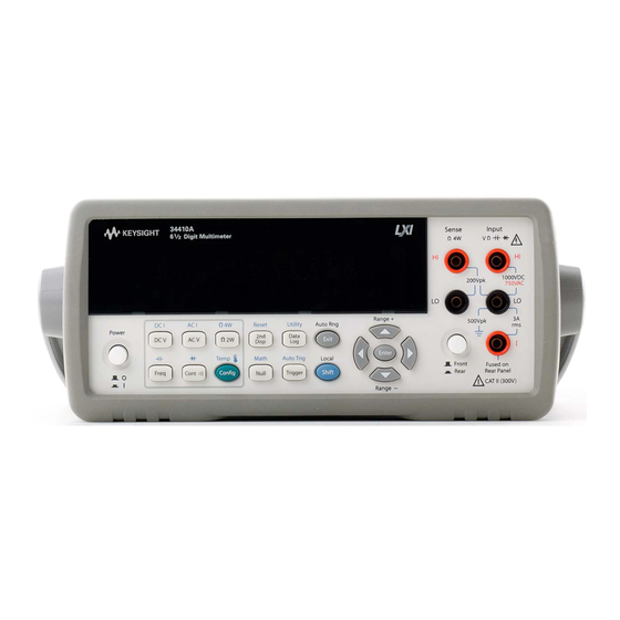
- Page 1 Agilent 34410A/11A 6 ½ Digit Multimeter (includes the L4411A 1U DMM) User’s Guide Agilent Technologies...
-
Page 2: Restricted Rights Legend
Notices Warranty Safety Notices © Agilent Technologies, Inc. 2005-2012 No part of this manual may be reproduced in The material contained in this docu- any form or by any means (including elec- ment is provided “as is,” and is sub-... -
Page 3: Safety Information
Safety Information Do not defeat power cord safety ground fea- WARN IN G WARN IN G ture. Plug in to a grounded (earthed) outlet. Do not use product in any manner not speci- Main Power and Test Input Dis- IEC Measurement Category II. The fied by the manufacturer. - Page 4 Protection Limits Input Terminal Protection Note: The 200 Vpk limit on the sense termi- nals is the Protection Limit. Operational Limits The Agilent 34410A/11A and L4411A Digital voltages in resistance measurements are Multimeters provide protection circuitry to much lower — less than 10 V in normal Protection Limits are defined for the input prevent damage to the instrument and to operation.
- Page 5 Additional Notices Waste Electrical and Agilent 34138A Test Lead Set Electronic Equipment (WEEE) The Agilent 34410A/11A is provided with Directive 2002/96/EC an Agilent 34138A Test Lead Set, described below. This product complies with the WEEE Direc- Test Lead Ratings tive (2002/96/EC) marking requirement. The affixed product label (see below) indi- Test Leads - 1000V, 15A cates that you must not discard this electri-...
- Page 6 This DoC applies to above-listed products placed on the EU market after: 17 January 2007 Date David L. Kepler Quality Manager For further information, please contact your local Agilent Technologies sales office, agent or distributor, or Agilent Technologies Deutschland GmbH, Herrenberger Straße 130, D 71034 Böblingen, Germany. 34410A/11A/L4411A User’s Guide...
- Page 7 Agilent 34410A/11A/L4411A at a Glance The Agilent 34410A, 34411A, and L4411A multimeters provide 6½-digit, high-performance dc and ac measurements. • Voltage and Current Measurements. DC and AC (true-rms). • Resistance Measurements. 2-wire and 4-wire. • Continuity and Diode Testing. • Frequency and Period Measurements. •...
- Page 8 The Front Panel at a Glance (34410A/11A) 1 On/Off Switch 8 Exit Key (Auto Range) 2 Measurement Function Keys 9 Shift Key (Local) 3 Configuration Key 10 Menu Navigation Keypad (Range) 4 Second Display Key (Reset) 11 Front/Rear Switch 5 Null Key (Math Functions) 12 HI and LO Sense Terminals (4-wire measurements) 6 Data Logger Key (Utility) 13 HI and LO Input Terminals (all functions except current)
- Page 9 The Rear Panel at a Glance (34410A/11A) 1 Current Input Fuse (front and rear) 2 HI and LO Sense Terminals (4-wire resistance and temperature) 3 HI and LO Input Terminals (voltage, resistance, and other functions) 4 Current Input Terminal (ac current and dc current only) 5 External Trigger Input (BNC) 6 Voltmeter Complete Output (BNC) 7 LAN Interface Connector...
- Page 10 The Display at a Glance (34410A/11A) Alphanumeric Displays: 1 Primary display line 2 Secondary display line Annunciators: Annunciators: (measurement in progress) 12 Shift (shift key just pressed) Hi-Z (high input impedance, Vdc only) 13 Math (dB or dBm function enabled) OComp (offset compensation) 14 Stats (statistics functions enabled) 6 ManRng (manual ranging)
-
Page 11: In This Guide
In This Guide… Quick Start In this chapter you prepare the multimeter for use and become familiar with the most common front-panel operations. Features and Functions In this chapter you will find a detailed description of the multimeter’s capabilities and operation. This chapter presents both front-panel and remote interface operation of the instrument. - Page 12 34410A/11A/L4411A User’s Guide...
-
Page 13: Table Of Contents
To Make a 4-Wire Temperature Measurement To Test Continuity To Check Diodes Other Basics of Operation If the Multimeter Does Not Turn On To Replace the Power-Line Fuse (34410A/11A) To Adjust the Carrying Handle To Rack Mount the Multimeter (34410A/11A) Agilent Technologies... -
Page 14: Basic Multimeter Operations
Quick Start Basic Multimeter Operations This section introduces the basics of the 34410A/11A multimeter, and how to use it. For basic information unique to the L4411A, refer to the L4411A Getting Started Guide N O TE (p/n L4411-90001). Preparing the Multimeter for Use To verify that your 34410A or 34411A multimeter is ready for use: 1 Check the list of supplied items. -
Page 15: Using The Front Panel (34410A/11A)
Quick Start Using the Front Panel (34410A/11A) This section introduces the 34410A/11A multimeter front panel. Front-Panel Keys The front panel provides keys to select various functions and operations. Pressing a measurement function key (e.g. ) selects that function. Press to enter the configuration menu for the selected measurement function. Most keys have a shifted function printed in blue above the key. -
Page 16: Front-Panel Display Shortcuts
Quick Start Front Panel Display Shortcuts Direct front panel shortcuts are provided for three commonly used display functions: ranging, digit masking, and integration time. Ranging. The multimeter’s manual range can be set directly from the navigation keypad. To manually change the current multimeter range, press . -
Page 17: Making Basic Measurements (34410A/11A)
Quick Start Making Basic Measurements (34410A/11A) This section introduces the many types of measurements that you can make with your 34410A/11A multimeter, and how to make connections for each measurement. Most basic measurements can be taken using the factory default settings. A more complete description of all multimeter functions, measurement parameter configuration and remote interface operation is provided in Chapter 2. -
Page 18: To Measure Dc Voltage
Quick Start To Measure DC Voltage Press to select the dc voltage function. • Ranges: 100 mV, 1 V, 10 V, 100 V, 1000 V • Configurable parameters: INTEGRATION, RANGE, INPUT Z (input impedance), AUTO ZERO, NULL, and NULL VALUE Connect test leads as shown: DC Voltage To Measure AC Voltage... -
Page 19: To Measure Dc Current
Quick Start To Measure DC Current Press to select the dc current function. • Ranges: 100 mA, 1 mA, 10 mA, 100 mA, 1 A, 3 A • Configurable parameters: INTEGRATION, RANGE, AUTO ZERO, NULL, and NULL VALUE Connect test leads as shown: DC Current To Measure AC Current Press... -
Page 20: To Make A 2-Wire Resistance Measurement
Quick Start To Make a 2-Wire Resistance Measurement Press to select the 2-wire resistance function. • Ranges: 100Ω, 1 kΩ, 10 kΩ , 100 kΩ , 1 MΩ, 10 MΩ, 100 MΩ , 1 GΩ • Configurable parameters: INTEGRATION, RANGE, OFFSET COMP, AUTO ZERO, NULL, and NULL VALUE Connect test leads as shown: Resistance... -
Page 21: To Measure Frequency
Quick Start To Measure Frequency Press to select the frequency function. • Measurement band: 3 Hz to 300 kHz • Input signal range: 100 mVAC to 750 VAC • Technique: reciprocal counting • Configurable parameters: GATE TIME, RANGE, AC FILTER, NULL and NULL VALUE Connect test leads as shown: AC Signal To Measure Period... -
Page 22: To Measure Capacitance
Quick Start To Measure Capacitance Press to select the capacitance function. • Ranges: 1 nF, 10 nF, 100 nF, 1 mF, 10 mF • Configurable parameters: RANGE, NULL, and NULL VALUE Connect test leads as shown: Capacitance To null–out the test lead capacitance: 1 Disconnect the + lead’s probe end from the test circuit, and leave open. -
Page 23: To Make A 2-Wire Temperature Measurement
Quick Start To Make a 2-Wire Temperature Measurement Press to select the temperature function. Then press and select RTD-2W or THERMISTOR-2W from the menu. • Probe types: 2.2 kΩ, 5 kΩ, 10 kΩ thermistors; 0.00385/°C RTD • Configurable parameters: PROBE TYPE, THERMISTOR or RTD value, AUTO ZERO, OFFSET COMP (RTD probes only), INTEGRATION, UNITS, NULL, and NULL VALUE Connect test leads as shown: Thermistor or RTD... -
Page 24: To Test Continuity
Quick Start To Test Continuity Press to select the continuity function. • Test current source: 1 mA • Beeper Threshold: beeps below 10Ω Connect test leads as shown: Open or Closed Circuit To Check Diodes Press to select the diode test function. •... -
Page 25: Other Basics Of Operation
Quick Start Other Basics of Operation This section covers basic troubleshooting and general use. If the Multimeter Does Not Turn On Use the following steps to help solve problems you might encounter when turning on the multimeter. If you need more help, see the Service Guide for instructions on returning the multimeter to Agilent for service. -
Page 26: To Replace The Power-Line Fuse (34410A/11A)
Quick Start To Replace the Power-Line Fuse (34410A/11A) Remove power cord first. Then follow these steps: Depress tab (1) and pull fuse holder (2) from Remove line-voltage selector from fuse rear panel. holder assembly. Agilent Part Number 2110-0817 (250 mA, 250V, slow-blow, 5x20mm) Rotate line-voltage selector and reinstall so Replace fuse holder assembly in rear panel. -
Page 27: To Adjust The Carrying Handle
Quick Start To Adjust the Carrying Handle To adjust the position, grasp the handle by the sides and pull outward. Then, rotate the handle to the desired position. Bench-Top Viewing Positions Carrying Position 34410A/11A/L4411A User’s Guide... -
Page 28: To Rack Mount The Multimeter (34410A/11A)
Quick Start To Rack Mount the Multimeter (34410A/11A) You can mount the 34410A/11A in a standard 19–inch rack cabinet using the available rack–mount kits. Instructions and mounting hardware are included with each kit. Any Agilent System II (half-width, 2U height) instrument of either the 272.3 mm or the 348.3 mm depth can be rack mounted side–by–side with the 34410A/11A. - Page 29 Contents Quick Start Basic Multimeter Operations Preparing the Multimeter for Use Using the Front Panel (34410A/11A) Front-Panel Keys 15 Front-Panel Display Shortcuts 16 Making Basic Measurements (34410A/11A) To Measure DC Voltage To Measure AC Voltage To Measure DC Current To Measure AC Current To Make a 2-Wire Resistance Measurement To Make a 4-wire Resistance Measurement To Measure Frequency...
- Page 30 Contents Features and Functions SCPI Commands Front Panel Features (34410A/11A) Front Panel Display Displayed Messages Self–Guiding Menus Annunciators Second Display Options Turning the Display Off Front–Panel Display Shortcuts Front Panel Alphanumeric Character Entry Front Panel Measurement Configuration Menus Configuring DC Voltage and DC Current Measurements Configuring AC Voltage and Current Measurements Configuring Resistance Measurements Configuring Frequency and Period Measurements...
- Page 31 Contents Auto Zero Ranging Null Measurements Miscellaneous Configuration Settings Radix Character (34410A/11A) Thousands Separator (34410A/11A) Beeper (34410A/11A) Math Functions dB Measurements dBm Measurements Using Statistics Limit Testing Triggering the Multimeter Selecting a Trigger Source Auto Triggering (34410A/11A) Single Triggering (34410A/11A) Reading Hold (34410A/11A) Immediate Triggering Software (Bus) Triggering...
- Page 32 Contents Remote Interface Configuration Configuring the GPIB Interface Configuring the USB Interface Configuring the LAN Interface Configuring LAN Parameters DHCP Auto–IP IP Address Subnet Mask Default Gateway Host Name DNS Server Web Password Instrument Unexpectedly Goes into Remote Setting up a LAN connection from the Front Panel Setting up a LAN connection from the Remote Interface Agilent 34410A/11A Web Interface Measurement Tutorial...
- Page 33 Contents True RMS AC Measurements True RMS Accuracy and High–Frequency Signal Content Estimating High–Frequency (Out–of–Band) Error Other Primary Measurement Functions Frequency and Period Measurement Errors DC Current Measurements Capacitance Measurements Temperature Measurements Probe Type Choice 2–Wire vs. 4–Wire Measurements Auto Zero On/Off Integration Offset Compensation NULL Reading...
- Page 34 Contents Specifications DC Characteristics AC Characteristics Frequency and Period Characteristics Capacitance Characteristics Temperature Characteristics Additional 34411A/L4411A Specifications Measurement and System Speeds System Speeds Data From Memory General Specifications (34410A/11A) General Specifications (L4411A) Triggering and Memory Dimensions To Calculate Total Measurement Error Interpreting Accuracy Specifications Transfer Accuracy 24–Hour Accuracy...
-
Page 35: Features And Functions
Configuring Frequency and Period Measurements Configuring Temperature Measurements Configuring Capacitance Measurements Continuity and Diode Tests Advanced Configuration Options Multimeter State Storage Accessing Reading Memory Front/Rear Input Terminal Switching (34410A/11A) Multimeter Reset DC Measurements Integration Time and Resolution DC Input Impedance Agilent Technologies... - Page 36 Features and Functions AC Measurements AC Filter Gate Time Auto Zero Ranging Null Measurements Miscellaneous Configuration Settings Radix Character (34410A/11A) Thousands Separator (34410A/11A) Beeper (34410A/11A) Math Functions dB Measurements dBm Measurements Using Statistics Limit Testing Triggering the Multimeter Selecting a Trigger Source Auto Triggering (34410A/11A) Single Triggering (34410A/11A) Reading Hold (34410A/11A)
-
Page 37: Scpi Commands
Features and Functions SCPI Commands The Agilent 34410A/11A/L4411A complies with the syntax rules and conventions of SCPI (Standard Commands for Programmable Instruments). For complete SCPI command syntax information, refer to the Agilent 34410A/11A/L4411A N O TE Programmer’s Reference Help. This is a standard Windows help system, provided on the Agilent 34410A/11A/L4411A Product Reference CD-ROM that came with your instrument. -
Page 38: Front Panel Features (34410A/11A)
Features and Functions Front Panel Features (34410A/11A) Front Panel Display The Agilent 34410A/11A provides a two–line, alphanumeric display, with annunciators to indicate certain non–default instrument states. Displayed Messages While taking measurements, the primary display line shows the current reading, with units (for example: “-0.001,02 VDC”). For some functions the second display line can be enabled to display a secondary measurement. - Page 39 Features and Functions • If the multimeter is in the remote interface mode (Remote annunciator is lit), pressing once returns the multimeter to local (front panel) (Local) operation. • Once you have entered a menu, use the keys to view and select a menu item from those displayed on the second line.
-
Page 40: Annunciators
Features and Functions Annunciators There are several annunciators, mostly in a line at the top of the display. Each annunciator lights to indicate a particular non–default meter state: • A measurement is in progress (the “sample annunciator”). • Hi–Z For DC voltage measurements in the 100 mV, 1 V or 10 V ranges, an input impedance of >10 GΩ... -
Page 41: Second Display Options
Features and Functions Second Display Options Many measurement functions allow a secondary measurement to be displayed simultaneously on the second display line: Primary Function Second Display Function – – DC V, DC I, AC V, AC I Peak Peak value Freq AC Voltage Temp... -
Page 42: Front-Panel Display Shortcuts
Features and Functions Front Panel Display Shortcuts – Direct front–panel shortcuts are provided for three commonly used display functions: ranging, digit masking, and integration time. These shortcuts are available only when you are not in a menu. Ranging. The meter range can be set directly from the navigation keypad. •... -
Page 43: Front Panel Alphanumeric Character Entry
Features and Functions • If the multimeter is configured to take the measurement using an aperture integration time, press to display APERTURE, with the current setting on the second line (for example, 101.005mSEC). You can then use the navigation keypad to change the aperture setting. The keys have their usual functions. -
Page 44: Front Panel Measurement Configuration Menus
Features and Functions Front Panel Measurement Configuration Menus Each measurement function is configured separately, except for Ω 2W and Ω 4W (which are partially inter–dependent), and frequency and period, (which share a configuration menu). The configuration settings (for example, integration, and range) for each measurement function are retained when switching between functions. -
Page 45: Configuring Ac Voltage And Current Measurements
Features and Functions Configuring AC Voltage and Current Measurements For ac voltage and ac current measurements, your menu selections are: AC FILTER, RANGE, NULL and NULL VALUE. • AC FILTER: Allows you to select one of three choices (3 HZ : SLOW, 20 HZ : MEDIUM, 200 HZ : FAST). -
Page 46: Configuring Frequency And Period Measurements
Features and Functions Configuring Frequency and Period Measurements For frequency and period measurements, your menu selections are: CONFIGURE, GATE TIME, RANGE, AC FILTER, NULL and NULL VALUE. • CONFIGURE: Allows you to select either FREQUENCY or PERIOD as the primary measurement. -
Page 47: Configuring Capacitance Measurements
Features and Functions • NULL: Allows you to enable (ON) or disable (OFF) the null measurement feature, which measures the difference between a stored null value and the input signal. • NULL VALUE: Allows you to view and edit the null value (if enabled). •... -
Page 48: Advanced Configuration Options
Features and Functions Advanced Configuration Options The Remote Interface Operation segments within the following topics describes how the N O TE instrument feature is used/accessed from a (remote) programming environment. For the L4411A, this represents the only method of accessing the instrument. See the L4411A Getting Started Guide for details. -
Page 49: Accessing Reading Memory
Features and Functions • Remote Interface Operation: Refer to the MEMory command subsystem in the Agilent 34410A/11A/L4411A Programmer’s Reference Help for a complete description and syntax of the commands that store, recall, and name multimeter states from the remote interface. Accessing Reading Memory Reading memory is accessed directly from the remote interface only. -
Page 50: Multimeter Reset
Features and Functions • Remote Interface Operation: The Front/Rear switch is manually switchable only, and cannot be controlled from the remote interface. The following query returns the current switch setting: ROUTe:TERMinals? The query returns either “FRON” or “REAR” Multimeter Reset The reset function resets most multimeter settings to their factory settings, except if the power–on state has been manually set to a stored state (see “Multimeter State Storage”... -
Page 51: Dc Measurements
Features and Functions DC Measurements Integration Time and Resolution For dc voltage, dc current, resistance, and temperature measurements, the multimeter provides two ways to set integration time, both of which affect the measurement resolution. These are in the number of power–line cycles (NPLCs) and aperture (settable in seconds). - Page 52 Features and Functions • Remote Interface Operation: The following commands set the integration time in NPLC: [SENSe:]VOLTage[:DC]:NPLC {< PLCs >>MIN>MAX>DEF} [SENSe:]CURRent[:DC]:NPLC {< PLCs >>MIN>MAX>DEF} [SENSe:]RESistance:NPLC {< PLCs >>MIN>MAX>DEF} [SENSe:]FRESistance:NPLC {< PLCs >>MIN>MAX>DEF} [SENSe:]TEMPerature:NPLC {< PLCs >>MIN>MAX>DEF} Each of these commands also has a query form. Refer to the Agilent 34410A/11A/L4411A Programmer’s Reference Help for a complete description and syntax for these commands.
-
Page 53: Dc Input Impedance
Features and Functions The following command (similar queries for current, resistance and temperature) returns whether aperture mode is enabled: [SENSe:]VOLTage[:DC]:APERture:ENABled? This query returns a “0” (disabled) or “1” (enabled). Refer to the Agilent 34410A/11A/L4411A Programmer’s Reference Help for a complete description and syntax for these commands. DC Input Impedance Applies to dc voltage measurements only. -
Page 54: Ac Measurements
Features and Functions AC Measurements AC Filter Applies to ac voltage, ac current, frequency, and period measurements only. The multimeter provides three bandwidth (ac signal filter) selections. Set the bandwidth for the lowest frequency you expect to encounter. Note that a lower bandwidth setting results in longer settling times, as shown in the table below. -
Page 55: Gate Time
Features and Functions Gate Time Applies to frequency and period measurements only. The multimeter provides four choices of gate time (also called aperture) for frequency or period measurements. The gate time selection affects resolution as shown below. Gate Time Resolution 1 ms 100 ppm x Range 10 ms... -
Page 56: Auto Zero
Features and Functions Auto Zero Auto zero is selectable for dc voltage, dc current, 2–wire resistance, and 2-wire temperature measurements only. Auto zero is always enabled for 4–wire resistance or 4–wire temperature measurements. When auto zero is ON (default) the multimeter internally disconnects the input signal immediately following each measurement, and takes a zero reading. -
Page 57: Ranging
Features and Functions Ranging Applies to all measurements except continuity and diode test, which use a fixed range. Temperature measurements always use autoranging. You can let the multimeter automatically select the range using autoranging, or you can select a fixed range using manual ranging. Autoranging is convenient because the multimeter automatically selects the appropriate range for sensing and displaying each measurement. - Page 58 Features and Functions • Remote Interface Operation: Autoranging may be enabled or disabled for the specified function using the following command: SENSe: <function> :RANGe:AUTO {OFF>ONCE>0>ON>1} where < function > = VOLTage:DC, VOLTage:AC, CURRent:DC, CURRent:AC, RESistance, FRESistance, or CAPacitance For < function > = FREQuency or PERiod, the range commands affect the ac signal input voltage range.
-
Page 59: Null Measurements
Features and Functions The first four readings are taken on the 1 Vdc range, but the autoranging feature switches to the 10 Vdc range for the final reading, which is a 20 percent overload for the 1 Vdc range. This is a typical 6½ digit behavior. For frequency measurements only, the 34410A/11A/L4411A is capable of displaying a full seven digits (for example, “999.980,3 HZ”). -
Page 60: Miscellaneous Configuration Settings
Features and Functions The following command queries the null measurement feature setting: SENSe:< function >:NULL[:STATe]? This query returns a “0” (OFF) or “1” (ON). The following command stores a null value for the specified function: SENSe:< function >:NULL[:VALue] {< value >>MIN>MAX} The following command queries the null value: SENSe:<... -
Page 61: Beeper (34410A/11A)
Features and Functions Beeper (34410A/11A) Normally, the multimeter emits a tone from the front panel whenever certain conditions are met (for example, the multimeter beeps when a stable reading is captured in reading hold mode). The beeper is factory set to ON, but may be disabled or enabled manually. -
Page 62: Math Functions
Features and Functions Math Functions In addition to providing a separate null–per–function measurement capability, the multimeter provides four math functions: dB measurements (dB), dBm measurements (dBm), statistics for accumulated readings (STATS), and limit testing (LIMITS). Only one of these math functions can be enabled at a time (in addition to the null measurement), and remains in effect until you turn it off or change it. -
Page 63: Db Measurements
Features and Functions dB Measurements Applies to ac voltage and dc voltage measurements only. Each dB measurement is the difference between the input signal and a stored relative value, with both values converted to dBm. dB = reading in dBm – relative value in dBm •... -
Page 64: Dbm Measurements
Features and Functions dBm Measurements Applies to ac voltage and dc voltage measurements only. The dBm function is logarithmic, and is based on a calculation of power delivered to a reference resistance, relative to 1 milliwatt. dBm = 10 x log (reading / reference resistance / 1 mW ) •... -
Page 65: Using Statistics
Features and Functions Using Statistics Applies to all measurement functions except continuity and diode test. From the front panel, you can view the following statistical data for any set of readings: average or mean (AVG), maximum (MAX), minimum (MIN), standard deviation (SDEV), and number of samples taken (COUNT). -
Page 66: Limit Testing
Features and Functions Limit Testing Applies to all measurement functions except continuity and diode test. The limit test function (LIMITS) enables you to perform pass/fail testing to upper and lower limits that you specify. You can set the upper and lower limits to any value between 0 and ±120% of the highest range, for the present function. -
Page 67: Triggering The Multimeter
Features and Functions Triggering the Multimeter The 34410A/11A/L4411A triggering system allows you to generate triggers either manually or automatically, take multiple readings per trigger, and insert a delay before each reading. The 34411A/L4411A also allows you to set a level for internal triggering, and to set up pre-triggering. -
Page 68: Auto Triggering (34410A/11A)
Features and Functions Auto Triggering (34410A/11A) This mode is available from the front panel only. The power–on trigger default mode for the multimeter is front panel operation, in auto trigger mode. • Auto triggering takes continuous readings at the fastest rate possible for the specified measurement configuration (function, range, resolution, and so forth). -
Page 69: Reading Hold (34410A/11A)
Features and Functions Reading Hold (34410A/11A) This mode is available from the front panel only. The reading hold mode allows you to capture and hold a stable reading on the front panel display. This is useful in situations when you want to take a reading, remove the test probes, and have the reading remain on the display. -
Page 70: Software (Bus) Triggering
Features and Functions Software (Bus) Triggering This mode is available from the remote interface only. The bus trigger mode corresponds in function to pressing the key from the front panel, except that the trigger is initiated by sending a bus trigger command, after selecting BUS as the trigger source. -
Page 71: Number Of Samples Per Trigger
Features and Functions Number of Samples per Trigger By default, when the multimeter is in the wait–for–trigger state, it takes one reading (or sample) each time you trigger the multimeter. You can, however, instruct the multimeter to take up to 50,000 readings (up to 1 million for the 34411A/L4411A) each time a trigger is initiated, whether from the front panel or remote interface. -
Page 72: Trigger Delay
Features and Functions • Remote Interface Operation: The following commands set the sample count (must be >1) and pre–trigger sample count: SAMPle:COUNt {<count>|MIN|MAX|DEF} SAMPle:COUNt:PRETrigger {<PT count >>MIN>MAX|DEF} Refer to the Agilent 34410A/11A/L4411A Programmer’s Reference Help for a complete description and syntax for this command. Trigger Delay You can manually specify a delay between the trigger signal and the first sample that follows. -
Page 73: Automatic Trigger Delay
Features and Functions If the multimeter is configured to take more than one sample per trigger, the effect of the trigger delay on subsequent samples depends on the sample source setting. Refer to the SAMPle:SOURce command description in the Agilent 34410A/11A/L4411A Programmer’s Reference Help for a detailed description. - Page 74 Features and Functions 2–wire Resistance Measurements: Range Trigger Delay Trigger Delay Trigger Delay (for ≤ 0.02 PLC) (for ≥ 1 PLC) (for 0.06 or 0.2 PLC) 100 Ω 80 μs 100 μs 130 μs 110 μs 130 μs 160 μs 1 kΩ...
-
Page 75: External Triggering
Features and Functions Temperature is measured using the 2–wire or 4–wire resistance function. The above tables N O TE for resistance apply to temperature, but all temperature measurements use autoranging. The range in use cannot be predicted; thus, nor can the delay. Use the TRIGger:DELay? command to query the actual trigger delay for a temperature measurement. - Page 76 Features and Functions • Front Panel Operation: The external trigger mode corresponds in function to pressing the key from the front panel, except that you apply the trigger signal to the Ext Trig connector. • Remote Interface Operation: The following command selects the trigger source from the external connector: TRIGger:SOURce EXTernal Refer to the Agilent 34410A/11A/L4411A Programmer’s Reference Help for...
-
Page 77: Trigger Slope
Features and Functions Trigger Slope You may select whether the multimeter uses the rising edge (POS) or falling edge (NEG) of the external trigger signal to trigger a reading, or (independently) for the voltmeter complete output signal. The default for both is NEG. -
Page 78: Data Logging
Features and Functions Data Logging The Data Logger feature (34410A/11A only) provides a front–panel user interface that allows you to set up data logging into the instrument’s non–volatile memory without programming, and without a connection to a computer. Once you have finished collecting data, you can view it from the front panel, or you can then connect your computer and import the data. - Page 79 Features and Functions • After the specified delay, the main display will show the data as it is collected, while the second display line shows a progress bar and the current count (down). • The multimeter will continue taking readings until the specified count or duration has been reached, unless the data logger is stopped manually.
- Page 80 Features and Functions • Web Interface Operation: To access the data in the multimeter’s non–volatile memory, launch the 34410A/11A Web Interface (see “Agilent 34410A/11A Web Interface” on page 98): Click on Browser Web Control to display the Control DMM dialog box: 34410A/11A/L4411A User’s Guide...
- Page 81 Features and Functions Now click on View Data. In the dialog, select Non–volatile Memory Readings and then click on Get Data to view the logged data: From this window, you can select and copy (see Web Interface Help) the data into another application using the Microsoft®...
-
Page 82: System-Related Operations
Features and Functions System-Related Operations The utility menu accesses the following system–related operations: self–test, display of error conditions, calibration, and instrument information. These features are described in the subsections that follow. The utility menu is also used to access the following three menus: •... -
Page 83: Error Conditions
Features and Functions Error Conditions When the front panel ERROR annunciator turns on (34410A/11A), one or more command syntax or hardware errors have been detected. A record of up to 20 errors can be stored in the instrument’s error queue. •... -
Page 84: Reading The Error Queue
Features and Functions Reading the Error Queue You can read the error queue either from the front panel, or from the remote interface. • Front Panel Operation: Press UTILITY MENU > SCPI ERRORS Scroll through the errors using the navigation keypad. Press to clear all errors from the queue. -
Page 85: Power-On And Reset State
Features and Functions Power-On and Reset State The tables that follow show the factory defaults for various instrument settings. The parameters marked with a bullet ( ● ) are stored in non–volatile memory, and are not affected by power–on or a system reset. For those parameters, the initial factory settings are shown. - Page 86 Features and Functions System–Related Operations Factory Setting ● ● Thousands Separator (34410A/11A) Display State (34410A/11A) Reading Memory Cleared – Error Queue Cleared at Power Not cleared by a front panel or remote interface Reset command ● ● Stored States No change ●...
-
Page 87: Remote Interface Configuration
Setting up a LAN connection from the Front Panel Setting up a LAN connection from the Remote Interface Agilent 34410A/11A Web Interface For remote interface configuration information specific to the L4411A, refer to the L4411A N O TE Getting Started Guide (p/n L4411-90001). Agilent Technologies... - Page 88 Remote Interface Configuration This chapter tells how to configure the Agilent 34410A/11A for remote interface communication. For additional information, refer to the: • Agilent USB/LAN/GPIB Connectivity Guide for interface configuration and troubleshooting information. This manual is found on the Agilent Automation–Ready CD–ROM or at www.agilent.com/find/connectivity.
-
Page 89: Configuring The Gpib Interface
Remote Interface Configuration Configuring the GPIB Interface Each device on the GPIB (IEEE–488) interface must have a unique address. You can set the multimeter’s address to any integral value between 0 and 30. The address is set to “22” when the instrument is shipped from the factory. •... -
Page 90: Configuring The Usb Interface
Remote Interface Configuration Configuring the USB Interface For the USB interface, no configuration parameters are required to set up the multimeter. Connect your multimeter to a USB port on your computer. Note that it may take several seconds for the computer to recognize and establish a connection to the multimeter. -
Page 91: Configuring The Lan Interface
Remote Interface Configuration Configuring the LAN Interface By default, LAN connectivity with DHCP (Dynamic Host Configuration Protocol) is enabled on the 34410A/11A. In many cases you can simply let DHCP assign the necessary parameters for a LAN connection. However, you can also turn off DHCP and set parameters manually. -
Page 92: Configuring Lan Parameters
Remote Interface Configuration Configuring LAN Parameters DHCP DHCP is a protocol for automatically assigning a dynamic IP address, subnet mask and default gateway to a device on a network, and is typically the easiest way to configure your multimeter for remote communication using the LAN interface. -
Page 93: Ip Address
Remote Interface Configuration IP Address An Internet Protocol (IP) Address is required for all IP and TCP/IP communications with the instrument. If DHCP is enabled (factory setting), the specified static IP address is not used. However, if the DHCP server fails to assign a valid IP address, or if DHCP and Auto–IP are both off, the currently configured static IP address will be used. -
Page 94: Default Gateway
Remote Interface Configuration Default Gateway A Default Gateway address allows the multimeter to communicate with systems that are not on the local subnet. Thus, this is the Default Gateway where packets are sent which are destined for a device not on the local subnet, as determined by the Subnet Mask setting. -
Page 95: Dns Server
Remote Interface Configuration DNS Server The Domain Name Service (DNS) is an Internet service that translates Domain names into IP addresses. Contact your network administrator to determine if DNS is being used and for the correct address. • If you change the DNS address, you must cycle power on the multimeter to activate the new setting. -
Page 96: Setting Up A Lan Connection From The Front Panel
Remote Interface Configuration Setting up a LAN connection from the Front Panel Press UTILITY MENU > REMOTE I/O > LAN > ENABLE LAN? > LAN SETTINGS > VIEW | MODIFY If you disable or re–enable the LAN interface, or any of the LAN services, you must cycle N O TE the power on the instrument to activate the new configuration. -
Page 97: Setting Up A Lan Connection From The Remote Interface
Remote Interface Configuration Setting up a LAN connection from the Remote Interface Use the following SCPI commands to configure the LAN interface. If you disable or re–enable the LAN interface, you must cycle the power for the change to N O TE take effect. -
Page 98: Agilent 34410A/11A Web Interface
Remote Interface Configuration Agilent 34410A/11A Web Interface The 34410A/11A provides a built–in Web Interface. You can use this interface over LAN for remote access and control of the multimeter using a Java–enabled Web browser, such as Microsoft® Internet Explorer. To access and use the 34410A/11A Web Interface: 1 Establish a LAN interface connection from your computer to the multimeter. -
Page 99: Measurement Tutorial
Noise Caused by Ground Loops Resistance Measurement Considerations 4–Wire Ohms Measurements Removing Test Lead Resistance Errors Minimizing Power Dissipation Effects Errors in High Resistance Measurements True RMS AC Measurements True RMS Accuracy and High–Frequency Signal Content Estimating High–Frequency (Out–of–Band) Error Agilent Technologies... - Page 100 Measurement Tutorial Other Primary Measurement Functions Frequency and Period Measurement Errors DC Current Measurements Capacitance Measurements Temperature Measurements Probe Type Choice 2–Wire vs. 4–Wire Measurements Auto Zero On/Off Integration Offset Compensation NULL Reading: High-Speed Measurements Making High–Speed AC Measurements Making High–Speed dc and Resistance Measurements Other Sources of Measurement Error Settling Time Effects Loading Errors (ac volts)
-
Page 101: Dc Measurement Considerations
Measurement Tutorial DC Measurement Considerations Thermal EMF Errors Thermoelectric voltages are the most common source of error in low–level dc voltage measurements. Thermoelectric voltages are generated when you make circuit connections using dissimilar metals at different temperatures. Each metal–to–metal junction forms a thermocouple, which generates a voltage proportional to the junction temperature. -
Page 102: Noise Rejection
Measurement Tutorial Noise Rejection Rejecting Power Line Noise Voltages – A desirable characteristic of integrating analog–to–digital (A/D) converters is their ability to reject power–line related noise present with dc input signals. This is called normal mode noise rejection, or NMR. The multimeter achieves NMR by measuring the average dc input by "integrating"... -
Page 103: Noise Caused By Magnetic Loops
Measurement Tutorial Noise Caused by Magnetic Loops If you are making measurements near magnetic fields, take caution to avoid inducing voltages in the measurement connections. You should be especially careful when working near conductors carrying large currents. Use twisted–pair connections to the multimeter to reduce the noise pickup loop area, or dress the test leads as close together as possible. -
Page 104: Resistance Measurement Considerations
Measurement Tutorial Resistance Measurement Considerations The multimeter offers two methods for measuring resistance: 2–wire and 4–wire ohms. For both methods, the test current flows from the input HI terminal and then through the resistor being measured. For 2–wire ohms, the voltage drop across the resistor being measured is sensed internal to the multimeter. -
Page 105: Removing Test Lead Resistance Errors
Measurement Tutorial Removing Test Lead Resistance Errors To eliminate offset errors associated with the test lead resistance in 2–wire ohms measurements, follow the steps below. 1 Short the ends of the test leads together. The multimeter displays the test lead resistance. 2 Press . -
Page 106: True Rms Ac Measurements
Measurement Tutorial True RMS AC Measurements True rms responding multimeters, like the Agilent 34410A/11A/L4411A, measure the "heating" potential of an applied voltage. Power dissipated in a resistor is proportional to the square of an applied voltage, independent of the waveshape of the signal. This multimeter accurately measures true rms voltage or current, as long as the wave shape contains negligible energy above the meter’s effective bandwidth. -
Page 107: True Rms Accuracy And High-Frequency Signal Content
Measurement Tutorial An ac–coupled true rms measurement is desirable when you are measuring small ac signals in the presence of large dc offsets. For example, this situation is common when measuring ac ripple present on dc power supplies. There are situations, however, where you might want to know the ac+dc true rms value. - Page 108 Measurement Tutorial On the following page, the first figure shows the Fourier Integral of two very μ μ different pulses: one of broad width (200 s); the other narrow (6.7 s). The second figure is an approximation of the shape of the input frequency response of the 34410A/11A/L4411A.
- Page 109 Measurement Tutorial 34410A/11A/L4411A User’s Guide...
-
Page 110: Estimating High-Frequency (Out-Of-Band) Error
Measurement Tutorial Estimating High Frequency (Out Band) Error – – – A common way to describe signal waveshapes is to refer to their “Crest Factor”. Crest factor is the ratio of the peak value to rms value of a waveform. For a pulse train, for example, the crest factor is approximately equal to the square root of the inverse of the duty cycle. - Page 111 Measurement Tutorial The following table shows the typical error for various pulse waveforms as a function of input pulse frequency: Typical error for square wave, triangular wave, and pulse trains of CF=3, 5, or 10 square wave triangle wave CF=3 CF=5 CF=10 –...
-
Page 112: Other Primary Measurement Functions
Measurement Tutorial Other Primary Measurement Functions Frequency and Period Measurement Errors The multimeter uses a reciprocal counting technique to measure frequency and period. This method generates constant measurement resolution for any input frequency. The multimeter's ac voltage measurement section performs input signal conditioning. -
Page 113: Capacitance Measurements
Measurement Tutorial Capacitance Measurements The multimeter implements capacitance measurements by applying a known current to the capacitor as shown below: An Illustration of the response curve while charging is shown below: Capacitance is calculated by measuring the change in voltage (DV) that occurs over a “short aperture”... - Page 114 Measurement Tutorial The measurement cycle consists of two parts: a charge phase (shown in the graph) and a discharge phase. The time–constant during the discharge phase is longer, due to a 100 kΩ protective resistor in the measurement path. This time–constant plays an important role in the resultant reading rate (measurement time).
-
Page 115: Temperature Measurements
Measurement Tutorial Temperature Measurements The multimeter allows the measurement of temperature by measurement of the temperature sensitive resistance of two different "Probe" types: the resistance temperature detector (RTD) of 0.00385/ C; and thermistors of 2.2 KΩ , 5 KΩ, or 10 KΩ). There are a number of measurement parameter and technique choices available to you, and these affect various aspects of the measurement: •... -
Page 116: Auto Zero On/Off
Measurement Tutorial Auto Zero On/Off Enabling the auto zero feature (ON) provides greater accuracy; however, the additional measurement (of zero) reduces the reading speed. Integration There are two methods of integrating the sampled data taken in the measurement, NPLC's and Aperture. NPLC's sets the number of power line cycles in the gating of the measurement. -
Page 117: High-Speed Measurements
Measurement Tutorial High-Speed Measurements Making High Speed AC Measurements – The multimeter's ac voltage and ac current functions implement three low–frequency filters. These filters allow you to trade–off minimum measured frequency for faster reading speed. The FAST filter settles in 0.025 seconds, and is useful for frequencies above 200 Hz. -
Page 118: Making High-Speed Dc And Resistance Measurements
Measurement Tutorial For ac voltage, additional settling time may be required when the dc level varies from sample to sample. The default sample delays allow for a dc level change of 3% of range for all filters. If the dc level change exceeds these levels, additional settling time is required. -
Page 119: Other Sources Of Measurement Error
Measurement Tutorial Other Sources of Measurement Error Settling Time Effects The multimeter has the ability to insert automatic measurement settling delays. These delays are adequate for resistance measurements with less than 200 pF of combined cable and device capacitance. This is particularly important if you are measuring resistances above 100 kΩ. -
Page 120: Measurements Below Full Scale
Measurement Tutorial Measurements Below Full Scale You can make the most accurate ac measurements when the multimeter is at or near the full scale of the selected range. Autoranging occurs at 10% (down–range) and 120% (up–range) of full scale. This enables you to measure some inputs at full scale on one range and 10% of full scale on the next higher range. - Page 121 Measurement Tutorial susceptible to noise pickup than a low–impedance source. You can reduce the high–frequency impedance of a source by placing a capacitor in parallel with the multimeter's input terminals. You may have to experiment to determine the correct capacitor value for your application. Most extraneous noise is not correlated with the input signal.
-
Page 122: Common Mode Errors
Measurement Tutorial Common Mode Errors Errors are generated when the multimeter's input LO terminal is driven with an ac voltage relative to earth. The most common situation where unnecessary common mode voltages are created is when the output of an ac calibrator is connected to the multimeter "backwards."... -
Page 123: Specifications
DC Characteristics AC Characteristics Frequency and Period Characteristics Capacitance Characteristics Temperature Characteristics Additional 34411A/L4411A Specifications Measurement and System Speeds General Specifications (34410A/11A) General Specifications (L4411A) Dimensions To Calculate Total Measurement Error Interpreting Accuracy Specifications Configuring for Highest Accuracy Measurements Agilent Technologies... - Page 124 Specifications These specifications apply when using the 34410A/11A/L4411A multimeter in an environment that is free of electromagnetic interference and electrostatic charge. When using the multimeter in an environment where electromagnetic interference or significant electrostatic charge is present, measurement accuracy may be reduced. Particularly note: •...
-
Page 125: Dc Characteristics
Specifications DC Characteristics Accuracy Specifications ±( % of reading + % of range ) Function Range Test Current or 24 Hour 90 Day 1 Year Temperature Burden Voltage ± 1 °C ± 5 °C ± 5 °C Coefficient/°C 0 °C –... - Page 126 Specifications Performance Versus Integration Time – 60Hz (50Hz) Power line frequency RMS Noise Adder % range Integration Time Resolution NMR db Readings / Number of Power ppm Range Second 10, 1000 V 1, 100 V 0.1 V Line Cycles (NPLC) Resistance Resistance 100 ohm...
- Page 127 Specifications DC Voltage Measurement Method: Continuously integrating multi–slope IV A/D converter 10 VDC Linearity: 0.0002% of reading + 0.0001% of range Input Resistance: 0.1 V, 1 V, 10 V Ranges Selectable 10 MΩ or >10 GΩ (For these ranges, inputs beyond ±17 V are clamped through 100 kΩ...
-
Page 128: Ac Characteristics
Specifications AC Characteristics Accuracy Specifications ±( % of reading + % of range ) Function Range Frequency Range 24 Hour 90 Day 1 Year Temperature ± 1 °C ± 5 °C ± 5 °C Coefficient/°C 0 °C – 5 °C) + 5 °C) 55 °C True RMS AC... - Page 129 Specifications Voltage Transfer Accuracy ( typical ) Frequency Error 10 Hz to 300 kHz (24 hour % of range + % of reading)/5 Conditions: - Sinewave input only using slow filter. - Within 10 minutes and ±0.5 °C. - Within ±10% of initial voltage and ±1% of initial frequency. - Following a 2–hour warm–up.
-
Page 130: Frequency And Period Characteristics
Specifications Frequency and Period Characteristics [ 1, 3 ] Accuracy Specifications ±( % of reading ) Function Range Frequency Range 24 Hour 90 Day 1 Year Temperature C ± 1 °C ± 5 °C ± 5 °C Coefficient 0 °C –... - Page 131 Specifications Frequency and Period Measurement Type: Reciprocal–counting technique. AC–coupled input using the AC voltage measurement function. Input Impedance: 1 MΩ ±2%, in parallel with <150 pF Input Protection: 750 V rms all ranges Measurement Considerations All frequency counters are susceptible to error when measuring low–voltage, low–frequency signals. Shielding inputs from external noise pickup is critical for minimizing measurement errors.
-
Page 132: Capacitance Characteristics
Specifications Capacitance Characteristics Accuracy Specifications ±( % of reading + % of range ) Function Range Test Current 24 Hour/90 Day/ Temperature 1 Year Coefficient ± 5 °C 0 °C – 5 °C) + 5 °C) 55 °C Capacitance 1 nF 500 nA 0.50 + 0.50 0.05 + 0.05... -
Page 133: Additional 34411A/L4411A Specifications
Specifications Additional 34411A/L4411A Specifications Resolution See table on page 126 Overall Bandwidth, DCV and DCI 15 kHz typical @ 20 µs aperture (–3 dB) Triggering Pre or Post, Internal or External, Positive or Negative Timebase Resolution 19.9524 µs, 0.01% accuracy Trigger Jitter 2 µs(p-p), 20 µs(p-p) when pre-triggered External Trigger Latency... -
Page 134: Measurement And System Speeds
Specifications Measurement and System Speeds DMM Measurements Speeds Direct I/O Measurements Measurement Single Reading – Measure and I/O Time Into Memory (Readings/Sec) Function Resolution GPIB USB 2.0 LAN (VXI-11) LAN (Sockets) (VM Complete) (NPLC) DCV (10 V Range) 0.001 0.0026 0.0029 0.0046 0.0032... -
Page 135: System Speeds
Specifications Direct I/O Measurements (any remote interface) Sustained maximum reading rate to I/O, 32 bit BINARY data ("SAMP:COUN 50000;:R?") – Function Resolution (NPLC) rdgs/Sec 0.001 50000 (34411A/L4411A) 0.006 10000 Fast Filter 2–Wire Ω 0.001 50000 (34411A/L4411A) 0.006 10000 4–Wire Ω 0.001 1500 (34411A/L4411A) 0.006... -
Page 136: Data From Memory
Specifications Data From Memory Maximum reading rate out of memory (Sample count 50000, trigger count 1, "FETC?" or "R?") Readings GPIB USB 2.0 LAN (VXI-11) LAN (Sockets) rdg/Sec rdg/Sec rgs/Sec rdg/Sec ASCII 4000 8500 7000 8500 4–byte Binary 89,000 265,000 110,000 270,000 8–byte Binary... -
Page 137: General Specifications (L4411A)
Specifications General Specifications (L4411A) Power supply: Universal 100V to 240V ±10% Power line frequency: 45 Hz to 440 Hz +/- 10% automatically sensed Power consumption: 50 VA peak (18W average) Operating Environment: Full accuracy for 0 °C to 55 °C Full accuracy to 80% R.H. -
Page 138: Dimensions
Specifications Dimensions 212.3 40.9 All dimensions are shown in millimeters 34410A/11A/L4411A User’s Guide... -
Page 139: To Calculate Total Measurement Error
Specifications To Calculate Total Measurement Error The multimeter's accuracy specifications are expressed in the form: ( % of reading + % of range ). In addition to the reading error and range error, you may need to add additional errors for certain operating conditions. Check the list below to make sure you include all measurement errors for a given function. - Page 140 Specifications Understanding the " % of range " Error The range error compensates for inaccuracies that result from the function and range you select. The range error contributes a constant error, expressed as a percent of range, independent of the input signal level. The following table shows the range error applied to the multimeter's 24 hour dc voltage specification.
-
Page 141: Interpreting Accuracy Specifications
Specifications Interpreting Accuracy Specifications Transfer Accuracy Transfer accuracy refers to the error introduced by the multimeter due to noise and short term drift. This error becomes apparent when comparing two – nearly equal signals for the purpose of "transferring" the known accuracy of –... -
Page 142: Configuring For Highest Accuracy Measurements
Specifications Configuring for Highest Accuracy Measurements The measurement configurations shown below assume that the multimeter is in its power on or reset state. It is also assumed that auto–ranging is enabled – to ensure proper full scale range selection. DC Voltage, DC Current, and Resistance Measurements: •... -
Page 143: A Appendix: Firmware And Driver Updates
Downloading the Update Utility and Firmware Downloading IVI-COM Driver Updates For firmware and driver update information specific to the L4411A, refer to the L4411A N O TE Getting Started Guide (p/n L4411-90001). Agilent Technologies... -
Page 144: Downloading The Update Utility And Firmware
Appendix: Firmware and Driver Updates Downloading the Update Utility and Firmware Agilent 34410A/11A firmware updates are installed in the instrument using the Agilent Firmware Update Utility. The utility and firmware file can be found on the Web at: www.agilent.com/find/34410A www.agilent.com/find/34411A Once this page is displayed, click on ‘Technical Support’... - Page 145 Appendix: Firmware and Driver Updates Depending on the interface to the 34410A or 34411A, the firmware update utility N O TE will require the instrument’s LAN address, GPIB address, or USB address/alias. Note this address before starting the utility. 1. From the directory where the update utility was installed, start the utility by selecting FirmwareUpdateUtility.exe.
- Page 146 Appendix: Firmware and Driver Updates The ‘Applicable Model’ window lists the instruments which may be updated by N O TE the specified firmware (.xs) image. The window is not used to select the instrument receiving the firmware update. 3. Select the I/O interface to the instrument and then select ‘Next’. Enter the machine name, IP address, GPIB address, or Alias,...
-
Page 147: Downloading Ivi-Com Driver Updates
Appendix: Firmware and Driver Updates Downloading IVI-COM Driver Updates An IVI-COM driver for the 34410A/11A is provided on the Product Reference CD-ROM (p/n 34410-13601). Updates to the IVI-COM driver can be found on the Web at: www.agilent.com/find/34410A www.agilent.com/find/34411A Once this page is displayed, click on ‘Technical Support’ under the heading “More Details”. - Page 148 Appendix: Firmware and Driver Updates 34410A/11A/L4411A User’s Guide...
- Page 149 Index Numerics Beeper, DC Voltage Measurements Bumper Removal, Configuring, 1-Year Specifications, Burden Voltage, Configuring for Accuracy, 24-hour accuracy, Errors In, Bus Triggering, 34410A, Hih Speed, firmware updates, Integration Integration Time, 34411A, Loading Error, Cable Capacitance, firmware updates, Specifications, Calibration, 90-Day Specifications, Thermal EMF Error, Calibration Errors, DC Volts Measurement,...
- Page 150 Index Measurement Error, Below Full Scale, Factory Settings, Keys, 8, 10, Burden Voltage, firmware updates Common Mode, downloads, Ground Loops, installation, High Resistance Measurements, LAN Interface, 88, update utility, Leakage Current, Leakage Current, Frequency Measurements, Loading, Limit TEsting, Configuring, Loadiong Errors, Limit Testing, Configuring for Accuracy, Low Level Measurments,...
- Page 151 Index Sample Count, Samples per Trigger, Period Measurements, TCP/IP, SCPI Configuring, Temperature Coefficients (and Commands, Accuiracy), Configuring for Accuracy, Language Conventions, Temperature Measurements, Errors In, Language Version, Configuring, Specifications, Second Display, Power Dissipation, Errors In, Selecting Front or Rear Terminals, NPLC, Power LIne Noise, Rejecting, Self-Test,...
- Page 152 Index Waste Electrical and Electronic Equipment Directive, Web Browser, Web Password, 91, 34410A/11A/L4411A User’s Guide...