Table of Contents
Advertisement
Quick Links
Advertisement
Chapters
Table of Contents
Troubleshooting

Related Manuals for Ricoh fax3310l


Summary of Contents for Ricoh fax3310l
-
Page 1: Operating Instructions
Operating Instructions <Basic Features> Getting Started Faxing Registering Troubleshooting Type for 3725/F9103/LF310/3310L Printed in China For safety, please read this manual carefully before you use this product and keep it handy UE USA H555-8600 for future reference. - Page 2 Two kinds of size notation are employed in this manual. With this machine refer to the inch version. 7. If you cannot correct the problem, please contact the RICOH CORP. CUSTOMER SUPPORT DEPT. at 1-800-FASTFIX for repair or warranty information. If the equipment is causing harm to the telephone network, the telephone company may request you to disconnect the equipment For good copy quality, the supplier recommends that you use genuine toner from the supplier.
-
Page 3: Table Of Contents
TABLE OF CONTENTS NOTICE ......................1 Safety Information ..................3 Safety During Operation ................3 Important Safety Instructions..............5 Grounding ...................... 5 Important Safety Instructions ................. 5 Caution ......................5 Positions of Labels and Hallmarks for R R WARNING and R R CAUTION ... - Page 4 2. Faxing Transmission Modes................21 Switching between Memory Transmission and Immediate Transmission..22 Setting Originals..................23 Loading Originals in the Document Feeder..........24 Original Sizes Difficult to Detect..............24 Memory Transmission ................25 Canceling a Memory Transmission ............27 Before the Start Key is Pressed ..............27 While the Original is Being Scanned............
- Page 5 Speed Dial ....................52 Registering ....................52 Editing ......................54 Deleting ....................... 55 Groups....................... 57 Registering ....................57 Editing ......................60 Editing a Group Name ................60 Adding a Fax Number to a Group.............. 61 Deleting ......................63 To delete a destination from a group ............63 To delete an entire group................
-
Page 7: Notice
NOTICE R CAUTION: Use of controls, adjustments or performance of procedures other than those specified herein may result in hazardous radiation exposure. Shielded interconnect cables must be employed with this equipment to ensure compliance with the pertinent RF emission limits governing this device. Direct (or indirect reflected) eye contact with the laser beam may cause serious eye damage. - Page 8 Note to users in Canada - Note: This Class B digital apparatus complies with Canadian ICES-003. Remarque concernant les utilisateurs au Canada - Avertissement: Cet appareil numérique de la classe B est conforme à la norme NMB-003 du Can- ada. - Notice about the Telephone Consumer Protection Act (Valid in USA only).
-
Page 9: Safety Information
Safety Information When using this machine, the following safety precautions should always be fol- lowed. Safety During Operation In this manual, the following important symbols are used: R WARNING: Indicates a potentially hazardous situation which, if instructions are not followed, could result in death or serious injury. R CAUTION: Indicates a potentially hazardous situation which, if instructions are not followed, may result in minor or moderate injury or damage to property. - Page 10 R CAUTION: • Protect the machine from dampness or wet weather, such as rain and snow. • Unplug the power cord from the wall outlet before you move the machine. While moving the machine, you should take care that the power cord will not be damaged under the machine.
-
Page 11: Important Safety Instructions
Important Safety Instructions Grounding In order to prevent potentially hazardous electrical shock, provide means of connecting to the protective grounding conductor in the building, wiring those grounding conductors of power cable and 3 pins plug. Important Safety Instructions Caution When using your telephone equipment, basic safety precautions should always be followed to reduce the risk of fire, electric shock and injury to persons, includ- ing the following: •... -
Page 12: Positions Of Labels And Hallmarks For R
Positions of Labels and Hallmarks for R WARNING and R R CAUTION This machine has labels and hallmarks for RWARNING,RCAUTION at the positions shown below. For safety, please follow the instructions and handle the machine as indicated. The inside of the machine becomes very hot. Do not touch the inside. Doing so could result in a burn. -
Page 13: Energy Star Program
ENERGY STAR Program As an ENERGY STAR Partner, we have determined that this machine model meets the ENERGY STAR Guidelines for energy efficiency. The ENERGY STAR Guidelines intend to establish an international energy-saving system for developing and introducing energy-efficient office equipment to deal with environmental is- sues, such as global warming. -
Page 14: Energy Saving Modes
Energy Saving Modes Energy Saving mode enables you to avoid using unnecessary power and econo- mize on electricity. Although we recommend you use this mode from the view- point of environmental consciousness, you can also turn it off. When you install this machines for the first time, Energy Saving mode is turned on by default. -
Page 15: Recycled Paper
Note ❒ When you load paper in Energy Saving mode, no error will be displayed even if the cassette is not pushed right in. ❒ After loading paper, press the Energy Saver key and check that "READY” is shown on the display. The Manual Receive indicator goes out in Energy Saving mode even if Manual Receive is turned on. -
Page 16: How To Read This Manual
How to Read this Manual Symbols The following set of symbols is used in this manual. R WARNING: This symbol indicates a potentially hazardous situation that might result in death or serious injury when you misuse the machine without following the in- structions under this symbol. -
Page 17: Manuals For This Machine
Manuals for This Machine Two Facsimile Reference manuals are provided, the Basic Features manual and the Advanced Features manual. Please refer to the manual that suits your needs. Basic Features (this manual) The Basic Features manual explains the most frequently used fax functions and operations. - Page 18 ❖ ❖ ❖ ❖ Chapter 9 Maintaining Your Machine Explains about changing the paper size in the paper trays, cleaning the scan- ner and so on. ❖ ❖ ❖ ❖ Chapter 10 Installation Explains about installation considerations, connecting to a telephone line, and connecting the power.
-
Page 19: Getting Started
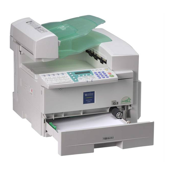
1. Getting Started Guide to Components Front View ADF Cover Front Cover Cover for the document feeder (ADF). Open this cover when changing the toner cassette and the photo conductor unit in- Release Button side the machine. Push this button to open the document Main Paper Tray feeder. -
Page 20: Side View
Getting Started Right Cover Original Tray Open this cover to remove jammed paper Place originals here for sending a fax and fed from the paper tray. copying. Original Output Tray Original guide Scanned originals are stacked here. Adjust the original guide to match the size of the originals. -
Page 21: Control Panel
Control Panel Control Panel User Function keys Add Toner indicator Each of these can be programmed for Blinks when toner is about to runout and rapid access to frequently used functions. lights continuously when toner has run out. ❖ ❖ ❖ ❖ Functions Programmed by Default Load Paper indicator Function Lights when a paper tray is empty or the... - Page 22 Getting Started { { { { On Hook Dial} } } } key Status Indicators Use to dial a number from the numeric These indicators keep you informed keypad without having to lift the hand- about the current status of the unit. set.
-
Page 23: Starting The Machine
Starting the Machine Starting the Machine To start the machine, turn on the Turning Off the Power power switch. Note Important ❒ This machine automatically enters ❒ Make sure that 100% is shown on Energy Saver mode if you do not the Fax standby display before you use the machine for a while. -
Page 24: Reading The Display
Getting Started Reading the Display The machine status and instructions are shown on the display. Note ❒ This machine automatically returns to the standby display if you do not use the machine for a certain period of time. You can select the period in Fax Reset Timer. -
Page 25: Communication Display
Reading the Display Communication Display Display Prompts While the machine is communicating, Depending on the situation, the ma- the status is displayed. chine will show various prompts on the display. ❖ ❖ ❖ ❖ Display during Memory Transmission ❖ ❖ ❖ ❖ Instructions and Requests or Reception: The destination's name or fax number appears on the top of the... - Page 26 Getting Started...
-
Page 27: Faxing
2. Faxing Transmission Modes ❖ ❖ ❖ ❖ Immediate Transmission There are two types of transmission. The machine dials immediately, ❖ ❖ ❖ ❖ Memory Transmission and transmits the fax while scan- When a fax document is stored in ning. memory, then transmission starts It is convenient when you would automatically. -
Page 28: Switching Between Memory Transmission And Immediate Transmission
Faxing Switching between Memory Transmission and Immediate Transmission Press the { { { { Memory Trans.} } } } key to switch between Memory Transmis- sion and Immediate Transmission. When the indicator of the { { { { Memory Trans.} } } } key is not lit, Immediate Transmission is selected. -
Page 29: Setting Originals
Setting Originals Setting Originals You can set your originals in the Doc- Note ument Feeder. ❒ When sending a fax, the image output at the other end depends on ❖ ❖ ❖ ❖ How to set A4, B5, A5, 5 "×... -
Page 30: Loading Originals In The Document Feeder
Faxing Note Loading Originals in the ❒ Set the originals gently. Document Feeder Reference Use the Document Feeder to scan in a For details about unsuitable stack of originals in one operation. originals, see p.127 “Originals The Document Feeder can handle sin- unsuitable for the Document gle-sided originals. -
Page 31: Memory Transmission
Memory Transmission Memory Transmission Memory Transmission is convenient Note because: ❒ Maximum number of Memory • Fax documents can be scanned Transmission files: 140 much more quickly. Your scanned ❒ Maximum number of destinations document is stored in the memory, per Memory Transmission: 140 an d t h en s en t aut o m at i c al l y, ❒... - Page 32 Faxing B B B B E E E E Press the { { { { Start} } } } key. Set the original. Note ❒ Do not open the Document Feeder while it is scanning in originals. Reference p.23 “Setting Originals” C C C C Select any scan settings you re- quire.
-
Page 33: Canceling A Memory Transmission
Canceling a Memory Transmission Canceling a Memory Transmission Before the Start Key is During Transmission Pressed Use this procedure to cancel a trans- mission after the original has been A A A A Press the { { { { Energy Saver / Clear scanned. -
Page 34: While The Original Is Awaiting Transmission
Faxing C C C C A A A A Press the { { { { Job Information} } } } key, Display the file you want to de- lete. and confirm that "1. Cancel TX / RX" is displayed. Enter the file number with the number keys, or search using 0 or D D D D Press the { { { { OK} } } } key. -
Page 35: Immediate Transmission
Immediate Transmission Immediate Transmission B B B B Immediate Transmission is conve- Set your original. nient when: Reference • You wish to send a document im- mediately as it is scanning. p.23 “Setting Originals” C C C C • You wish to quickly check whether Select any scan settings you re- you have successfully connected quire. - Page 36 Faxing Reference p.41 “Own Name/Fax Head- er/Own Fax Number” After transmission the machine will return to standby display.
-
Page 37: Canceling An Immediate Transmission
Canceling an Immediate Transmission Canceling an Immediate Transmission Before the Start key is Pressed A A A A Press the { { { { Energy Saver / Clear Modes} } } } key. Note ❒ When you have already set the original, you can also cancel the transmission by removing the original from the machine. -
Page 38: Scan Settings
Faxing Scan Settings ❖ ❖ ❖ ❖ Fine (8× × × × 15.4 lines/mm, 200× × × × 400dpi) You may wish to send many different types of fax messages. Some of these Select for originals with very fine may be difficult to reproduce at the details or when you require the other end. -
Page 39: Original Type
Scan Settings ❒ Usually, transmission takes short- Original Type er when Auto resolution is select- e d t h an D et a il r e so lu tion is If your original contains photographs selected. However, transmission or colored illustrations, select Half- for some originals containing nor- tone to optimize image clarity. -
Page 40: Dialing
Faxing Dialing There are four main ways to dial a Note number: ❒ If you make a mistake, press the { { { { Clear/Stop } } } } key and enter ❖ ❖ ❖ ❖ Entering Numbers Directly again. See p.34 “Entering Numbers Di- ❒... -
Page 41: Pause
Dialing Note Tone ❒ If a memory file is awaiting trans- This function allows a machine con- mission and the "Exceeded the message is dis- nected to a pulse dialing line to send Max.Cannot Add" played when dialing with the tone signals (for example if you want to use a special service on a tone dial- number keys, you cannot dial any... -
Page 42: Using Speed Dials
Faxing A A A A Make sure that the machine is in Using Speed Dials standby display. B B B B You can specify destinations simply Set your original and select any by pressing the { { { { Speed Dial} } } } key and a scan settings you require. -
Page 43: Using Groups
Dialing C C C C Press the { { { { Speed Dial} } } } key. Using Groups You can store multiple destinations as a single Group and simply specify a particular Group. You must store the destinations' fax number in a Group beforehand. -
Page 44: When Specifying A Group With A Quick Dial
Faxing When Specifying a Group with a Quick When Specifying a Group with the Group Dial Make sure that the Memory Trans- Make sure that the Memory Trans- mission indicator is lit, if not, press mission indicator is lit, if not, press the { { { { Memory Trans.} } } } key to light it. -
Page 45: Reception Modes
Reception Modes Reception Modes ❒ Set a smaller number of rings The machine can treat incoming fax messages and telephone calls in three for the telephone answering ways. machine than for the fax ma- chine. ❖ ❖ ❖ ❖ Manual Receive ❒... - Page 46 Faxing D D D D Press 0 0 0 0 or 1 1 1 1 until " 3. Setup " is displayed. E E E E Press the { { { { OK} } } } key. F F F F Press 0 0 0 0 or 1 1 1 1 until “...
-
Page 47: Own Name/Fax Header/Own Fax Number
3. Registering Own Name/Fax Header/Own Fax Number Make sure that all necessary settings Note are made before connecting your ma- ❒ In some areas, the Own Fax chine to the telephone line. Number is preprogrammed by your service representative, and ❖... -
Page 48: Registering
Registering F F F F Press 0 0 0 0 or 1 1 1 1 until "6. Fax Infor- Registering mation" is displayed. The following procedure describes how to make initial settings. A A A A Press the { { { { User Tools} } } } key. G G G G Press the { { { { OK} } } } key. - Page 49 Own Name/Fax Header/Own Fax Number L L L L Press the { { { { OK} } } } key. Note ❒ The format of the number is The programmed Own Name is normally as follows: Interna- displayed. tional Dial Prefix, Your Country Code, Your Area Code (do not insert a pause after your Area Code), followed by your tele-...
-
Page 50: Editing
Registering F F F F Press 0 0 0 0 or 1 1 1 1 until "6. Fax Infor- Editing mation" is displayed. The following procedure describes how to edit initial settings. A A A A Press the { { { { User Tools} } } } key. G G G G Press the { { { { OK} } } } key. -
Page 51: Deleting
Own Name/Fax Header/Own Fax Number F F F F Press 0 0 0 0 or 1 1 1 1 until "6. Fax Infor- Deleting mation" is displayed. The following procedure describes how to delete initial settings. A A A A Press the { { { { User Tools} } } } key. -
Page 52: Quick Dial
Registering Quick Dial To save time, you can program a fax Note number that you use often into a ❒ You can confirm fax numbers Quick Dial key. Then, whenever you stored in Quick Dials on the Quick are sending a message to that loca- Dial List. - Page 53 Quick Dial E E E E H H H H Press the { { { { OK} } } } key. Press the { { { { OK} } } } key. The fax number is programmed. F F F F Display the number of the Quick I I I I Dial key you want to register.
-
Page 54: Editing
Registering L L L L D D D D Press the { { { { OK} } } } key. Press the { { { { OK} } } } key. If you want to store another Quick Confirm that " 1. Prog. Quick Dial " Dial, go to step E. -
Page 55: Deleting
Quick Dial J J J J Press the { { { { Clear/Stop} } } } key, and Deleting th en r een ter th e des tination name. The following procedure describes how to delete fax numbers registered Note in Quick Dial keys. -
Page 56: Quick Dial Key Label (Dial Label)
Registering E E E E Press 0 0 0 0 or 1 1 1 1 until " 2. Del. Quick Quick Dial Key Label (Dial label) Dial " is displayed. You can print a template that can be used to make labels for Quick Dial keys. -
Page 57: Label Paper
Quick Dial Label paper AUG. 21. 2002 11:22AM... -
Page 58: Speed Dial
Registering Speed Dial A A A A Press the { { { { User Tools} } } } key. Registering If you register numbers in Speed Di- als, you can specify the fax number simply by pressing the { { { { Speed Dial} } } } key, and entering a two-digit Speed Dial number. - Page 59 Speed Dial G G G G J J J J Display the number of the Speed Enter the Destination name. Dial you want to register (00 to 49). Enter the Speed Dial number with the number keys, or search using 0 or 1.
-
Page 60: Editing
Registering F F F F Press the { { { { OK} } } } key. Editing The following procedure describes how to edit registered Speed Dial numbers. G G G G Display the number of the Speed A A A A Press the { { { { User Tools} } } } key. -
Page 61: Deleting
Speed Dial M M M M Press 0 0 0 0 or 1 1 1 1 to select "On" or Deleting "Off". The following procedure describes how to delete fax numbers in Speed Dials. Limitation Note ❒ If a registered Speed Dial is being ❒... - Page 62 Registering E E E E Press 0 0 0 0 or 1 1 1 1 until " 4. Del. Speed Dial " is displayed. F F F F Press the { { { { OK} } } } key. G G G G Display the Speed Dial number you want to delete (00 to 49).
-
Page 63: Groups
Groups Groups If you regularly broadcast documents Registering to the same set of destinations, you can combine these numbers into a You can register the following items group. Then just select the group and in a Group: each number will be dialed in se- quence automatically. - Page 64 Registering A A A A ❒ If you register a Group with the Press the { { { { User Tools} } } } key. number keys when a file is waiting to be transmitted, a message is shown. You sometimes cannot reg- ister any more destinations even when the number of specified des- tination is 68 or less.
- Page 65 Groups G G G G J J J J Press the 0 0 0 0 or 1 1 1 1 to select " Add " Display the number of the Group you want to register (1 to 5). or " Exit ". Enter the group number with the number keys, or search using 0 or K K K K...
-
Page 66: Editing
Registering R R R R C C C C Press the { { { { User Tools} } } } key to re- Press the { { { { OK} } } } key. turn to standby display. Editing Confirm that " 1. Program / Delete You can edit the group name or add "... -
Page 67: Adding A Fax Number To A Group
Groups K K K K Press the { { { { Clear/Stop} } } } key, and Adding a Fax Number to a Group then enter the new name. A A A A Press the { { { { User Tools} } } } key. Note ❒... - Page 68 Registering G G G G M M M M Display the number of the group Specify the destination using one to which you want to add a num- of the following three methods: ber (1 to 5). Enter the fax number with the Enter the group number with the number keys.
-
Page 69: Deleting
Groups R R R R Press the { { { { OK} } } } key. Deleting The following procedure describes how to delete a destination from a group. S S S S Press 0 0 0 0 or 1 1 1 1 to select "Yes" if the •... - Page 70 Registering E E E E L L L L Press 0 0 0 0 or 1 1 1 1 until " 5. Prog. Press the { { { { OK} } } } key. Group Dial " is displayed. M M M M Press 0 0 0 0 or 1 1 1 1 to display the desti- F F F F Press the { { { { OK} } } } key.
-
Page 71: To Delete An Entire Group
Groups S S S S B B B B Press the { { { { OK} } } } key. Press 0 0 0 0 or 1 1 1 1 until " 2. Fax Fea- tures " is displayed. If you selected "No", go to step U. C C C C Press the { { { { OK} } } } key. - Page 72 Registering - To change and delete Quick Dials programmed as groups: To store an entire group under a dif- ferent Quick Dial key, or to delete the group from the Quick Dial key alto- gether, perform the following proce- dure: Press the { { { { User Tools} } } } key.
-
Page 73: Entering Characters
Entering Characters Entering Characters This section describes how to enter characters. Available Characters • Letters: ABCDEFGHIJKLMNOPQRSTUVWXYZabcdefghijklmnopqrstuvwxyz • Symbols: – _ (space) . , ( ) / @ & $ ! ' # p % + : ; < = > ? ^ [ ] ` { | } ∼ •... -
Page 74: How To Enter Characters
Registering { { { { Clear/Stop} } } } key Deletes the character at the cursor posi- - Wild Cards tion. If the cursor is placed to the right of the last character at the right end of a line, When you register other parties' Own that character will be deleted. -
Page 75: Troubleshooting
4. Troubleshooting Loading Paper in the Main Paper Tray C C C C If there is no paper in the main paper Push the metal plate down, and tray, the B indicator on the control then square the paper and load it panel lights. -
Page 76: Adjusting Volume
Troubleshooting Adjusting Volume B B B B You can change the volume of the fol- Press 0 0 0 0 or 1 1 1 1 until " 2. Fax Fea- lowing sounds the machine makes. tures " is displayed. ❖ ❖ ❖ ❖ On Hook Sounds when you press the { { { { On Hook Dial} } } } key. - Page 77 Adjusting Volume H H H H Press 0 0 0 0 or 1 1 1 1 to adjust the vol- ume. I I I I Press the { { { { OK} } } } key. The volume is adjusted. If you want to adjust another item, repeat steps G to I.
-
Page 78: Clearing Original Jams
Troubleshooting Clearing Original Jams If an original is jammed, the hindica- C C C C Remove the original. tor on the Control Panel blinks and “ Clear Misfed Original (S) “ is dis- played. Perform the following procedure to clear the jammed original. A A A A Open the ADF cover. -
Page 79: Clearing A Copy, Fax, Or Print Jam
Clearing a Copy, Fax, or Print Jam Clearing a Copy, Fax, or Print Jam B B B B If a copy, fax, or printed paper is Open the blue cover. jammed, the hindicator on the Con- trol Panel blinks and “ Clear Misfed Paper “... -
Page 80: Error Messages
Troubleshooting Error Messages The following messages may appear while you are operating or programming the machine. Message Problem/Solution No Files Exist No polling reception operations have been programmed. There are no documents in memory waiting for transmis- sion. Incorrect file number. Check the file number and try again. Cannot Combine : (currently se- Appears when you attempt to select a function that cannot lected function) - Page 81 Error Messages Message Problem/Solution This Dial is in Use. Cannot Delete. This Quick Dial is being used (such as for a Send Later This Dial is in Use. Cannot Transmission). Change. Some Page(s) are Blank An almost entirely blank document was scanned. Check your document.
-
Page 82: When The Receive File Indicator Is Lit
Troubleshooting When the Receive File Indicator is Lit If the Receive File indicator is lit, a message has been received but could not be printed for some reason. The message was stored in memory (Substitute Recep- tion). When you solve the problem, the message will be automatically printed out. -
Page 83: Solving Problems
Solving Problems Solving Problems This table lists some common problems and their solutions. Problem Required Action Printed or sent image contains spots. The Document Feeder (ADF) or scanner is dirty. Clean them. Make sure that ink or correction fluid is dry before set- ting the original. -
Page 84: Index
INDEX Add Toner indicator , 15 Editing Fax Header , 44 ADF Cover , 13 Groups , 60 Adjusting Volume Alarm , 70 Own Fax Number , 44 Dialing , 70 Own Name , 44 Key Tone , 70 Quick Dial , 48 On Hook , 70 Speed Dial , 54 Reception , 70... - Page 85 Job Information key , 15 Quick Dial , 46 Deleting , 49 Dialing , 35 Dial label , 50 LCD display , 15 Editing , 48 Loading Paper , 69 Registering , 46 Load Paper Indicator , 15 Quick Dial keys , 16 Lower Right Cover , 13 Low-power Mode , 7 Receive File Indicator , 15 , 76...
- Page 86 Tone , 35 Transmission Modes , 21 Trans. Option key , 15 Troubleshooting , 69 Error Messages , 74 TTI→Fax Header , 41 User Function keys , 15 User Tools key , 16 Ventilation hole , 14 Volume , 70 Wild Cards , 68 USA H555...
- Page 87 Operating Instructions <Advanced Features> Transmission Options Job Information Other Transmission Features Reception Features Copying Facsimile User Tools Key Operator Settings Solving Operation Problems Maintaining Your Machine Installation Appendix Type for 3725/F9103/LF310/3310L Printed in China For safety, please read this manual carefully before you use this product and keep it handy UE USA H555-8700 for future reference.
- Page 88 Introduction In accordance with IEC 60417, this machine uses the following symbols for the main power switch: a means POWER ON. This manual contains detailed instructions on the operation and maintenance of this machine. To get b means POWER OFF. maximum versatility from this machine all operators should carefully read and follow the instructions in this manual.
- Page 89 TABLE OF CONTENTS How to Read this Manual ................1 Symbols ......................1 Manuals for This Machine................2 Advanced Features (this manual) ..............2 Basic Features ....................2 1. Transmission Options Sending at a Specific Time (Send Later) ..........3 Fax Header Print ..................
- Page 90 More Transmission Functions ..............29 If Memory Runs Out While Storing an Original ..........29 Checking the Transmission Result............... 29 Broadcasting Sequence ................30 Sending a Fax Message Immediately ............30 Broadcasting : Checking Progress............... 30 Automatic Redial ..................30 Batch Transmission..................
- Page 91 6. Facsimile User Tools Counters ....................45 Programs....................46 Storing a Program ..................46 Using a Program ..................47 Changing a Program ................... 47 Editing the Program Name................47 Deleting a Program ..................48 Storing an Often Used Document (Auto Document)......49 Storing an Auto Document ................
- Page 92 Energy Save Timer ..................83 User Parameters ..................85 Changing the User Parameters ..............89 Printing the User Parameter List..............90 Personal Codes.................... 91 Registering and Editing................91 Deleting...................... 92 Printing the Personal Code List ..............93 Restricted Access ..................94 ID Code ......................
- Page 93 10.Installation Before Installation .................. 121 Machine Environment ................122 Location...................... 122 Connecting the Power and Switching On ..........123 Connecting to a Telephone Line and an External Telephone .... 124 Connecting to a Telephone Line ..............124 Connecting an External Telephone............124 11.Appendix Specifications ..................
-
Page 95: How To Read This Manual
How to Read this Manual Symbols The following set of symbols is used in this manual. R WARNING: This symbol indicates a potentially hazardous situation that might result in death or serious injury when you misuse the machine without following the in- structions under this symbol. -
Page 96: Manuals For This Machine
Manuals for This Machine Two Facsimile Reference manuals are provided, the Basic Features manual and the Advanced Features manual. Please refer to the manual that suits your needs. Advanced Features (this manual) The Advanced Features manual describes more advanced functions and also ex- plains settings for key operators. -
Page 97: Transmission Options
1. Transmission Options Sending at a Specific Time (Send Later) F F F F Using the Send Later function, you Press 0 0 0 0 or 1 1 1 1 to select "On". can delay transmission of your fax message until a specified time. This allows you to take advantage of off- peak telephone line charges without having to be by the machine at the... - Page 98 Transmission Options L L L L Specify the destination. If you want to specify another des- tination, press the { { { { OK} } } } key and repeat step L. M M M M Press the { { { { Start} } } } key. Note ❒...
-
Page 99: Fax Header Print
Fax Header Print Fax Header Print H H H H N ormally, the Fax Header pro - Press the { { { { Trans. Option} } } } key. grammed in your machine is printed at the top of each of the pages you transmit when they are received at the other end. -
Page 100: Sending Confidential Messages
Transmission Options Sending Confidential Messages This feature is called Confidential Note Transmission. Use this feature if you ❒ A Confidential ID can be any 4- do not want your message to be digit number except 0000. picked up casually by anybody at the ❒... - Page 101 Sending Confidential Messages Confidential ID Override Option: A Press 0 0 0 0 or 1 1 1 1 to select "Over- ride". B Press the { { { { OK} } } } key. Confidential ID Override is set. C Enter the Confidential ID (4- digits) with the number keys.
-
Page 102: Label Insertion
Transmission Options Label Insertion With this function, you can have the Note receiver's name programmed in ❒ You can set this function for each Quick Dial or Speed Dial printed on destination. the message when it is received at the other end. -
Page 103: Calling To Request A Message (Polling Reception)
Calling to Request a Message (Polling Reception) Calling to Request a Message (Polling Reception) Use this function if you want to poll a Limitation message from another terminal. You ❒ Polling Reception requires that the can also poll documents from many other machine can perform Polling terminals. -
Page 104: File Reserve Report (Polling Rx)
Transmission Options F F F F I I I I Press the { { { { OK} } } } key. Specify the other party's fax num- ber. G G G G Select the type of Polling Recep- J J J J Press the { { { { Start} } } } key. -
Page 105: Communication Result Report (Polling Rx)
Calling to Request a Message (Polling Reception) Communication Result Report (Polling RX) This report is printed after a Polling Reception has been completed and shows the result of the Polling Recep- tion. You can check the date and time, Oth- er party's name and result with this report. - Page 106 Transmission Options...
-
Page 107: Job Information
2. Job Information Canceling Transmission or Reception B B B B Transmission files are originals that Press the { { { { Job Information} } } } key. have been stored in memory and are awaiting transmission. The functions that produce transmission files are Memory Transmission and Polling Reception. -
Page 108: Printing A List Of Files In Memory (Print File List)
Job Information Printing a List of Files in Memory (Print File List) Print this list if you wish to find out which files are stored in memory and what their file numbers are. Knowing the file number can be useful (for ex- ample when erasing files). -
Page 109: Printing A Stored Message (Print Tx File)
Printing a Stored Message (Print TX File) Printing a Stored Message (Print TX File) If you wish to check the contents of a fax that is stored in memory and has not been sent yet, use this procedure to print it out. A A A A Make sure that the machine is in Facsimile mode and the standby... -
Page 110: Printing A Confidential Fax Message
Job Information Printing a Confidential Fax Message A A A A This feature is designed to prevent Press the { { { { Job Information} } } } key. messages from being picked up casu- B B B B ally by anyone when they are re- Press 0 0 0 0 or 1 1 1 1 until "4. -
Page 111: Printing A Memory-Locked Message
Printing a Memory-locked Message Printing a Memory-locked Message D D D D This is a security function that pre- Press the { { { { OK} } } } key. vents unauthorized individuals from E E E E reading printed messages. If Memory Enter the Memory Lock ID (4 dig- Lock is switched on, all received mes- its) with the number keys. -
Page 112: Printing The Journal
Job Information Printing the Journal When automatic communication report printing is turned on, the Journal is printed automatically after every 50 communications (receptions + transmis- sions). You can also print a copy of the Journal at any time by following the pro- cedure below. -
Page 113: Report Formats
Printing the Journal Report Formats MAR. 10. 2002 11:07AM The Mode Column The Footnote on the Journal Codes and alphabet on this column in- Transmission counter: Total number of form the type of communication. These transmitted pages codes are explained on the bottom of the Reception counter: Total number of re- report. - Page 114 Job Information...
-
Page 115: Other Transmission Features
3. Other Transmission Features Handy Dialing Functions A A A A Set your original and select any Chain Dial scan settings you require. B B B B This function allows you to compose Press Quick Dial key { { { { 03} } } } . a telephone number from various parts, some of which may be regis- tered in Quick Dials or Speed Dials... -
Page 116: Telephone Directory
Other Transmission Features Telephone Directory Redial This function lets you find a regis- The machine can recall the last 10 des- tered Speed Dial quickly by just en- tinations that have been dialed. If you tering a single letter, for example, the wish to send a message to a destina- first letter of the name registered for tion which you faxed recently, the Re-... -
Page 117: On Hook Dial
On Hook Dial On Hook Dial D D D D You can send a fax message without When the line is connected and lifting the receiver, while still listen- you hear a high-pitched tone, ing to the dial tone. press the { { { { Start} } } } key. If the other party has a telephone fax Note machine, you can talk by lifting the... -
Page 118: Manual Dial
Other Transmission Features Manual Dial The external telephone is required. You can send a fax message using an external telephone. Note ❒ The result of transmission with manual dial is not mentioned in the Transmission Result Report (Immediate Transmission). A A A A Place your original, and then se- lect any scan settings you require. -
Page 119: Transmission Features
Transmission Features Transmission Features C C C C Press 0 0 0 0 or 1 1 1 1 until " 2. SEP " is SEP Code displayed. If you want to receive a message stored in the memory of another par- ty's fax machine, use this function. -
Page 120: Sub Code
Other Transmission Features H H H H ❒ You can store IDs in Quick Dials, Press 0 0 0 0 or 1 1 1 1 until " 4. Polling Speed Dials, and Groups. RX" is displayed. ❒ Messages you send using this function are marked "SUB"... -
Page 121: Closed Network Transmission
Transmission Features B Press 0 0 0 0 or 1 1 1 1 until " 3. SID " is Closed Network Transmission displayed. This function ensures that you do not send confidential messages to the wrong machine. The ID Codes of the C Press the { { { { OK} } } } key c o m m u n i c a t i n g m a c h i n e s a r e checked. -
Page 122: Scanner Cleaning Message
Other Transmission Features Scanner Cleaning Message If dirt is stuck to the scanner, the other party receives fax messages with black lines. When the scanner is dirty, the warning message "Scanner Needs Cleaning" is displayed. If this mes- sage is displayed, wipe the exposure glass and white strip to remove the dirt, and then press the { { { { OK} } } } key. -
Page 123: More Transmission Functions
More Transmission Functions More Transmission Functions If Memory Runs Out While Checking the Transmission Storing an Original Result A A A A • Turn on the printing of the Com- If you run out of memory while munication Result Report if you storing an original (free space want a report to be printed after r e a c h e s 0 % ) ,... -
Page 124: Broadcasting Sequence
Other Transmission Features Broadcasting Sequence Automatic Redial If you dial several destinations for the If a fax message could not be trans- same message (Broadcasting), the mitted because the line was busy or messages are sent in the order in an error occurred during transmis- which they were dialed. -
Page 125: Dual Access
More Transmission Functions ❒ Standard Memory Transmission is Dual Access used instead of Parallel Memory Transmission in the following cas- The machine can scan other messages into memory even while sending a • When the line is busy and could fax message from memory, receiving not be connected to a message into memory , or automat-... -
Page 126: Printed Reports
Other Transmission Features Printed Reports You can obtain reports from your ma- Communication Result Report chine either by having your machine print them out automatically, or by (Switch 03, Bit 0) printing them out yourself. This report is printed when a Memo- Note ry Transmission is completed so you ❒... -
Page 127: Transmission Result Report (Immediate Transmission) (Switch 03, Bit 5)
Printed Reports Transmission Result Report (Immediate Transmission) (Switch 03, Bit 5) If you turn on the printing of this re- port, a report will be printed after ev- ery Immediate Transmission so you have a record of whether the trans- mission was successful or not. - Page 128 Other Transmission Features...
-
Page 129: Reception Features
4. Reception Features General Immediate Reception Memory Reception Each page of a received fax message is The machine waits until all pages of printed as soon as it is received. This the message have been received into method is used for standard fax mes- memory before printing the message. -
Page 130: Printing Documents That Have Been Received Into Memory (Substitute Reception)
Reception Features ❒ If free memory reaches 0% during Note Substitute Reception, any further ❒ If the memory free space reaches reception becomes impossible and 0% during Memory Reception, the the current communication is ter- machine can no longer receive the minated. -
Page 131: Receiving Messages In Telephone Mode
General Important ❒ If a sender does not program their name or fax number, the machine may reject an impor- tant fax message. We recom- mend that you ask important senders to register their name or fax number in advance. ❖... -
Page 132: Printing Options
Reception Features Printing Options Center Mark Checkered Mark When this function is turned on, When this function is turned on, a marks are printed halfway down the checkered mark is printed on the first left side and at the top center of each page of fax messages to help you sep- page received. -
Page 133: Reception Time
Printing Options Reception Time Page Separation and Length Reduction When this function is turned on, you can have the date and time when a When the size of a received message message was received printed at the is longer than the paper loaded in the bottom of the received image. -
Page 134: When There Is No Paper Of The Correct Size
Reception Features When There is No Paper of the Correct Size If there is no paper in your machine that matches the size of a received message, the machine will choose a paper size based upon the paper you have available. For example, if your machine has A4L and 8 ”×11”L installed and you re- ceive a A5K size message, check the A5K column of the table below. - Page 135 Printing Options Note ❒ The paper size used to print a received message may be different from the size of the sent original. Reference p.39 “Page Separation and Length Reduction”...
- Page 136 Reception Features...
-
Page 137: Copying
5. Copying Copying A A A A If you need to make a copy and there Press the { { { { Copy} } } } key. is no copier available, use your fax machine. Just place your original in the feeder, and press the { { { { Copy} } } } key. -
Page 138: Copying On Special Paper
Copying F F F F Press the { { { { Start} } } } key. Copying starts. When copying has finished, the machine returns to standby dis- play. Note ❒ To stop copying while it is in progress, press the { { { { Stop} } } } key. Then open the right cover and remove any paper left. -
Page 139: Facsimile User Tools
6. Facsimile User Tools Counters E E E E This function allows you to check the Press the { { { { User Tools} } } } key. total number of transmitted, received, The machine returns to standby scanned, and printed pages on the display. -
Page 140: Programs
Facsimile User Tools Programs If you regularly send messages to Storing a Program particular destinations using the same features, you can save a lot of re- You can register the following items petitive keypad operation by storing in Keystroke Programs: these settings in a Keystroke Pro- gram. -
Page 141: Using A Program
Programs F F F F Press the { { { { OK} } } } key. Editing the Program Name "Programmed" is displayed on the screen and the original is scanned To edit the program name, perform the following procedure. A A A A If you only want to register the Press the { { { { User Tools} } } } key. -
Page 142: Deleting A Program
Facsimile User Tools I I I I C C C C Press the { { { { Clear/Stop} } } } key, and Press the { { { { OK} } } } key. then enter the program's name. Confirm that "1. Program / Delete" J J J J is displayed. -
Page 143: Storing An Often Used Document (Auto Document)
Storing an Often Used Document (Auto Document) Storing an Often Used Document (Auto Document) If you find that you often have to send To register a document in a Quick Di- a particular page to people (for exam- al, perform the following procedure. ple, a map, a standard attachment, or A A A A Set your document and select any... -
Page 144: Sending An Auto Document As An Attachment
Facsimile User Tools H H H H Display the number of the Quick Sending an Auto Document as Dial where you want to register an Attachment the document. Press the Quick Dial, or scroll using To send an Auto Document as an at- 0 or 1 and press the { { { { OK} } } } key. -
Page 145: Changing An Auto Document
Storing an Often Used Document (Auto Document) G G G G Display the number of the Quick Changing an Auto Document Dial whose name you want to ed- You can change an Auto Document Press the Quick Dial, or scroll us- registered in Quick Dial by deleting ing 0 or 1 and press the { { { { OK} } } } the Auto Document, and then regis-... -
Page 146: Deleting An Auto Document
Facsimile User Tools G G G G Display the number of the Quick Deleting an Auto Document Dial where the document you want to delete is registered. To delete an Auto Document, per- Press the Quick Dial, or scroll us- form the following procedure. -
Page 147: User Function Keys
User Function Keys User Function Keys You can program each of the User Function keys ({ { { { F1} } } } to { { { { F5} } } } ) with a function that you use frequently. When you wish to use that function, instead of having to search through several menus to find it, just press the appropriate User Func- tion key. -
Page 148: Making A User Function Key Assignment
Facsimile User Tools H H H H Press 0 0 0 0 or 1 1 1 1 to display the func- Making a User Function Key tion name you want to assign. Assignment A A A A Press the { { { { User Tools} } } } key. I I I I Press the { { { { OK} } } } key. -
Page 149: Deleting A User Function Key
User Function Keys I I I I Press 0 0 0 0 or 1 1 1 1 to display " None ". Deleting a User Function Key To delete a User Function key, per- form the following procedure. A A A A J J J J Press the { { { { User Tools} } } } key. -
Page 150: Printing Reports/Lists
Facsimile User Tools Printing Reports/Lists B B B B This function allows you to print the Press 0 0 0 0 or 1 1 1 1 until " 2. Fax Fea- following reports and lists manually. tures " is displayed. Select a report or list as needed. - Page 151 Printing Reports/Lists Printing the Quick Dial List Printing the Group Dial List A Press 0 0 0 0 or 1 1 1 1 until " 3. Dial List A Press 0 0 0 0 or 1 1 1 1 until " 3. Dial List "...
- Page 152 Facsimile User Tools C Scroll 0 0 0 0 or 1 1 1 1 , or press the Printing the Quick Dial Label Quick Dial key that contains the Auto Document Original A Press 0 0 0 0 or 1 1 1 1 until " 4. Quick you want to print.
-
Page 153: Adjusting The Display Contrast
Adjusting the Display Contrast Adjusting the Display Contrast Use this function to adjust the bright- ness of the display. A A A A Press the { { { { User Tools} } } } key. B B B B Press 0 0 0 0 or 1 1 1 1 until " 2. Fax Fea- tures "... -
Page 154: Setting The Date And Time
Facsimile User Tools Setting the Date and Time H H H H Use this function to set your ma- Use the number keys to enter the chine's internal clock to the current year. time and date. If the current date and time are wrong, use this procedure to correct them. -
Page 155: Setting The Auto Ring Time
Setting the Auto Ring Time Setting the Auto Ring Time H H H H In Auto Select mode, the machine Enter the new number using the rings a number of times to give you number keys. the chance to pick up the handset be- fore taking the call automatically. -
Page 156: Changing The Paper Size Setting
Facsimile User Tools Changing the Paper Size Setting F F F F When you change a paper size on the Press 0 0 0 0 or 1 1 1 1 until "7. Tray Paper main paper tray, optional paper tray Size"... -
Page 157: Changing The Paper Type For Bypass Tray
Changing the Paper Type for Bypass Tray Changing the Paper Type for Bypass Tray H H H H You can print the original to OHP Choose the paper type using 0 0 0 0 or transparencies and thick paper using 1 1 1 1 . -
Page 158: Setting The Fax Reset Timer
Facsimile User Tools Setting the Fax Reset Timer H H H H This machine automatically returns Press 0 0 0 0 or 1 1 1 1 to select a period of to the standby display if you do not time. use the machine for a certain period of time. -
Page 159: On Hook Timeout
On Hook Timeout On Hook Timeout H H H H This machine automatically cancels Press 0 0 0 0 or 1 1 1 1 to select a period of the On Hook Dial mode if you do not time. dial a number from the number keys for a certain period of time after pressing the { { { { On Hook Dial} } } } key. -
Page 160: Selecting The Display Language
Facsimile User Tools Selecting the Display Language If you would rather use another lan- guage for messages and a display, fol- low the procedure below. Note ❒ Make sure that your machine is in standby display before following this procedure. If the standby dis- play is not shown when you start, the display may become tempo- rarily jumbled up. -
Page 161: Key Operator Settings
7. Key Operator Settings Function List Here is a list of the functions that are available for setting. Please refer to the ref- erence page numbers for more information. Display Description Reference (Specs.) 1. ADF Allows you to clear the counter after re- p.69 “Resetting the ADF Counter”... - Page 162 Key Operator Settings Display Description Reference (Specs.) 11. Select Line Allows you to select an internal G3 com- p.96 “Select Line” munication line or external telephone line for your fax machine. 12. PSTN Ac- Allows you to specify the code used to p.97 “PSTN Access Number”...
-
Page 163: Using Key Operator Settings
Using Key Operator Settings Using Key Operator Settings F F F F This chapter explains about functions Press { { { { 2} } } } { { { { 2} } } } { { { { 2} } } } { { { { 2} } } } . the key operator handles. -
Page 164: Authorized Reception
Key Operator Settings F F F F Press { { { { 2} } } } { { { { 2} } } } { { { { 2} } } } { { { { 2} } } } . Authorized Reception You can block junk fax messages and save paper by limiting the fax mes-... - Page 165 Using Key Operator Settings A Press 0 0 0 0 or 1 1 1 1 until "2. Program Registering a Specified Sender Sender" is displayed. for Authorized Reception Follow this procedure to register specified senders for Authorized Reception. Registration uses the B Press the { { { { OK} } } } key.
-
Page 166: Memory Lock
Key Operator Settings A Press 0 0 0 0 or 1 1 1 1 to select "3. De- Memory Lock lete Sender". This is a security function to prevent unauthorized individuals from read- ing printed fax messages. When B Press the { { { { OK} } } } key. Memory Lock is switched on, all re- ceived messages are stored in memo- C Press the 0 0 0 0 or 1 1 1 1 key to select... - Page 167 Using Key Operator Settings D D D D C Press the { { { { OK} } } } key. Press 0 0 0 0 or 1 1 1 1 until " 4. Key Op. Tools " is displayed. Registering a Specified Sender for Memory Lock You can register Specified Senders E E E E...
-
Page 168: Specified Tray
Key Operator Settings A Press 0 0 0 0 or 1 1 1 1 to select " 3. De- Specified Tray lete Sender ". Use this function to have messages from specified senders printed on dif- ferent paper. For example, imagine B Press the { { { { OK} } } } key. - Page 169 Using Key Operator Settings B B B B B Press 0 0 0 0 or 1 1 1 1 to select "On" to Press 0 0 0 0 or 1 1 1 1 until " 2. Fax Fea- switch this feature on, or select tures "...
-
Page 170: Forwarding
Key Operator Settings F Press the { { { { OK} } } } key. C Press the { { { { Start} } } } key. The list prints. The specified sender is regis- tered. Note If you want to register another ❒... -
Page 171: Switching Forwarding On/Off
Using Key Operator Settings Limitation Switching Forwarding On/Off ❒ The Forwarding function does not A A A A forward messages received with Press the { { { { User Tools} } } } key. Polling Reception mode. ❒ You cannot register a sender who does not have an Own Name or Own Fax Number. -
Page 172: Registering Forwarding Stations
Key Operator Settings K K K K E E E E Press 0 0 0 0 or 1 1 1 1 to “On” to switch Press the { { { { OK} } } } key. this function on, or select “Off” to F F F F Press { { { { 2} } } } { { { { 2} } } } { { { { 2} } } } { { { { 2} } } } . -
Page 173: Editing A Forwarding Station
Using Key Operator Settings O O O O U U U U Press the { { { { OK} } } } key. Press the { { { { User Tools} } } } key to re- turn to the standby display. The Forwarding Station's fax num- ber is registered. -
Page 174: Editing A Specified Sender
Key Operator Settings J J J J Press 0 0 0 0 or 1 1 1 1 until " 2. Prog. Sta- Deleting a Forwarding Station tion " is displayed. To delete a Forwarding Station, per- form the following procedure. A A A A Press the { { { { User Tools} } } } key. -
Page 175: Deleting A Specified Sender
Using Key Operator Settings K K K K F F F F Press the { { { { OK} } } } key. Press { { { { 2} } } } { { { { 2} } } } { { { { 2} } } } { { { { 2} } } } . L L L L Press 0 0 0 0 or 1 1 1 1 to display the fax number of the Forwarding Sta-... -
Page 176: Printing The Specified Sender List
Key Operator Settings Q Q Q Q F F F F Use 0 0 0 0 or 1 1 1 1 to display the Speci- Press { { { { 2} } } } { { { { 2} } } } { { { { 2} } } } { { { { 2} } } } . fied Sender you want to delete. -
Page 177: Energy Save Timer
Using Key Operator Settings F F F F Press { { { { 2} } } } { { { { 2} } } } { { { { 2} } } } { { { { 2} } } } . Energy Save Timer Use this function to have the fax ma- chine turn its heater on and off auto-... - Page 178 Key Operator Settings K K K K C Press 0 0 0 0 or 1 1 1 1 to select the day Press the { { { { User Tools} } } } key. of the week. The fax machine returns to stand- D Press the { { { { OK} } } } key.
-
Page 179: User Parameters
Using Key Operator Settings User Parameters The User Parameters allows you to customize various settings to match your needs. To change the function settings, set the user parameter switches. Preparation Access to some User Parameter Settings requires installation of optional equipment or that other settings be made beforehand. - Page 180 Key Operator Settings Switch Item 0 Default setting for printing the Forwarding Mark. FORWARDING MARK 1 Default setting for the Cen- ter Mark. CENTER MARK 2 Default setting for printing the Reception Time. RECEPTION TIME 3 Print Sender Information (TSI Print) 4 Default setting for the Checkered Mark.
- Page 181 Using Key Operator Settings Switch Item 0 Store incoming faxes when machine is out of supplies. SUBSTITUTE RECEP- TION 1 Default setting for Substi- Reject (If no Accept (Free) tute Reception. name or fax number is re- CONDITIONS OF MEM- ceived) ORY RECEPTION 4 Restricts fax machine us-...
- Page 182 Key Operator Settings Switch Item 3,2 Authorized Reception 00: Off 01: Received messages only from senders whose Own Name/Own Fax Number are registered 11: Received messages only from senders whose Own Name/ Own Fax Number are not registered 5, 4 Specified Tray Selection 00: Off 01: Messages from senders whose Own Name/Own Fax Number are...
-
Page 183: Changing The User Parameters
Using Key Operator Settings Switch Item 1 Distinctive Ring 2 Toner Saving Mode 7 Copy Mode Not Possible Possible 0 Use the G3 line as an internal extension, or an outside line. PABX/PSTN 1: PABX 0: PSTN 7,6,5 Set the tray which is selected first when copying. 001: Tray1 010: Tray2 111: Bypass Tray... -
Page 184: Printing The User Parameter List
Key Operator Settings J J J J Press the { { { { OK} } } } key. Printing the User Parameter List Print this list to see the current User Parameter settings. A A A A Press the { { { { User Tools} } } } key. For a list of the switches and set- tings, see p.85 “User Parameters”. -
Page 185: Personal Codes
Using Key Operator Settings J J J J Press the 0 0 0 0 or 1 1 1 1 key until " 2. Personal Codes Print List " is displayed. This function allows you to keep track of machine usage. When Per- sonal Codes are programmed, users have to enter their Personal Code be- K K K K... - Page 186 Key Operator Settings D D D D N N N N Press 0 0 0 0 or 1 1 1 1 until " 4. Key Op. Press the { { { { OK} } } } key. Tools " is displayed. O O O O Press the { { { { User Tools} } } } key to re- turn to the standby display.
- Page 187 Using Key Operator Settings J J J J D D D D Press 0 0 0 0 or 1 1 1 1 until " 2. Delete " is Press 0 0 0 0 or 1 1 1 1 until " 4. Key Op. displayed.
-
Page 188: Registering And Editing
Key Operator Settings B B B B Enter your personal code with the Restricted Access number keys. Use this function to limit transmis- sion to specific users. When turned on, users must enter a previously as- signed Personal Code in order to C C C C transmit originals. -
Page 189: Registering
Using Key Operator Settings ❖ ❖ ❖ ❖ Confidential ID F F F F Press { { { { 2} } } } { { { { 2} } } } { { { { 2} } } } { { { { 2} } } } . This ID is required for printing a message received with the Confi- dential Reception function. -
Page 190: Line Type
Key Operator Settings J J J J Press 0 0 0 0 or 1 1 1 1 to set your machine Line Type for a tone dial line or a pulse dial line. You must match the fax machine to the type of line you use: a tone line or a pulse line. -
Page 191: Pstn Access Number
Using Key Operator Settings G G G G To register an PSTN access number, Press the { { { { OK} } } } key. perform the following procedure. H H H H Press 0 0 0 0 or 1 1 1 1 until "11. Select A A A A Press the { { { { User Tools} } } } key. -
Page 192: Memory File Transfer
Key Operator Settings K K K K D D D D Press the { { { { OK} } } } key. Press 0 0 0 0 or 1 1 1 1 until "4. Key Op. Tools" is displayed. L L L L Press the { { { { User Tools} } } } key to re- turn to the standby display. -
Page 193: Margin Adjust
Using Key Operator Settings H H H H Press 0 0 0 0 or 1 1 1 1 until "14. Margin Margin Adjust Adjust" is displayed. If image positioning needs to be ad- justed slightly, adjust the margins for the appropriate tray (the main paper tray, the optional paper tray unit, or I I I I Press the { { { { OK} } } } key. -
Page 194: Rds (Remote Diagnostic System)
Key Operator Settings O O O O F F F F Press the { { { { OK} } } } key. Press { { { { 2} } } } { { { { 2} } } } { { { { 2} } } } { { { { 2} } } } . The margins are set. -
Page 195: Solving Operation Problems
8. Solving Operation Problems Printing the Help List Press the { { { { Help} } } } key and { { { { Start} } } } key to print a copy of the Help List which contains brief descriptions about the following features: •... -
Page 196: Clearing A Copy, Fax Or Print Jam
Solving Operation Problems Clearing a Copy, Fax or Print Jam Clearing a Copy, Fax, or Print Jam in the Optional Paper Tray Unit To clear jams in the optional paper tray unit, perform the following pro- cedure. A A A A Open the lower right cover. -
Page 197: Reading Reports
Reading Reports Reading Reports If a file has been deleted from memo- Error Report ry, a Power Failure Report is auto- matically printed as soon as power is An error report is printed when a restored. This report can be used to message could not be successfully identify lost files. - Page 198 Solving Operation Problems - RDS (Remote Diagnostic System) If your machine has a problem, a ser- vice representative can perform vari- o u s d i a g n o s t i c t a s k s o v e r t h e telephone line from the service sta- tion to try to find out what is wrong with your machine.
-
Page 199: Maintaining Your Machine
9. Maintaining Your Machine Loading paper in the Optional Paper Tray Unit A A A A E E E E Make sure that the optional paper Readjust the back fence and side tray unit is not being used. fences. B B B B Important Pull out the paper tray until it ❒... -
Page 200: Loading Paper In The Bypass Tray
Maintaining Your Machine Loading paper in the Bypass Tray C C C C The following procedure describes Gently insert the copy paper face how to load paper in the bypass tray. d o w n a n d a d j u s t t h e p a p e r A A A A guides. - Page 201 Loading paper in the Bypass Tray D D D D Push down the paper guide re- lease lever. Note ❒ If you set A4, 8 " × 14" or larg- er paper, hold the edge of the paper and push down the paper guide release lever.
-
Page 202: Changing The Paper Size In The Main Paper Tray
Maintaining Your Machine Changing the Paper Size in the Main Paper Tray A A A A D D D D Make sure that the paper tray is While pressing the release lever, not being used. adjust the side fences. B B B B Pull out the paper tray until it stops. - Page 203 Changing the Paper Size in the Main Paper Tray G G G G Adjust the side and back fences to the new paper size. Important ❒ When setting small quantities of paper, be careful not to squeeze in the side fence too much or pa- per will not be fed properly.
-
Page 204: Changing The Paper Size In The Optional Paper Tray Unit
Maintaining Your Machine Changing the Paper Size in the Optional Paper Tray Unit A A A A D D D D Make sure that the paper tray is While pressing the release lever, not being used. adjust the side fences. B B B B Pull out the paper tray until it stops. - Page 205 Changing the Paper Size in the Optional Paper Tray Unit F F F F Adjust the side and back fences to the new paper size. Important ❒ When loading small quantities of paper, be careful n ot to squeeze in the side fence too much or paper will not be fed properly.
-
Page 206: Cleaning The Scanner
Maintaining Your Machine Cleaning the Scanner To maintain the machine, clean the scanner regularly. A A A A While pushing the release button, open the ADF unit. B B B B Wipe the white strip (1) and expo- sure glass (2). Use a soft dry cloth. -
Page 207: Replacing The Adf Maintenance Kit
Replacing the ADF Maintenance Kit Replacing the ADF Maintenance Kit A A A A In order to ensure maximum perfor- A message on the display prompts mance of your fax machine, the ADF you to replace the ADF Mainte- Maintenance Kit is provided. You can nance Kit when it is time for re- replace the ADF Maintenance Kit af- placement. -
Page 208: Replacing The Photo Conductor Unit (Pcu)
Maintaining Your Machine Replacing the Photo Conductor Unit (PCU) A A A A D D D D Push the lever (A A A A ) and pull out Turn Off the Power Switch. the toner cassette holding A A A A and B B B B . - Page 209 Replacing the Photo Conductor Unit (PCU) G G G G J J J J Pull out the PCU holding the han- Push the PCU until it locks into dle. place. H H H H K K K K Take out the new PCU from the Insert the connector.
- Page 210 Maintaining Your Machine M M M M Pull the two red tags to remove the plastic strips. N N N N Return the toner cassette. Push the toner cassette until it locks into place. O O O O Close the right cover and front cover.
-
Page 211: Replacing The Toner Cassette
Replacing the Toner Cassette Replacing the Toner Cassette B B B B R WARNING: Push the lever (A A A A ) and pull out • Do not incinerate spilled toner the old toner cassette holding A A A A or used toner. - Page 212 Maintaining Your Machine D D D D Remove the tape from the toner cassette. E E E E Replace the toner cassette and make sure it locks securely into place. F F F F Close the front cover.
-
Page 213: Toner Cassette Storage
Toner Cassette Storage Toner Cassette Storage R WARNING: • Do not incinerate spilled toner or used toner. Toner dust might ignite when exposed to an open flame. • Dispose of the used toner car- tridge in accordance with the local regulations. R CAUTION: •... - Page 214 Maintaining Your Machine...
-
Page 215: Before Installation
10. Installation Before Installation Before installing your machine, read the safety instructions at the begin- ning of this manual. To install the ma- chine, follow these procedures: Find a suitable location for the ma- chine. Remove all the pieces of tape at- tached to the machine. -
Page 216: Machine Environment
Installation Machine Environment When choosing a location for your machine, please follow the safety in- structions given in the first section. Location For the best possible performance, in- stall your machine in a place which satisfies the following conditions: • Not exposed to direct sunlight •... -
Page 217: Connecting The Power And Switching On
Connecting the Power and Switching On Connecting the Power and Switching On R WARNING: • Connect the power cord direct- ly into a wall outlet and never use an extension cord. A A A A Plug in the cable to the outlet. B B B B Turn the power switch on. -
Page 218: Connecting To A Telephone Line And An External Telephone
Installation Connecting to a Telephone Line and an External Telephone Connecting to a Telephone Line Connecting an External Telephone Following the instructions for con- necting it to a telephone line. A A A A Plug the handset jack into the There are similar sockets located at “TEL”... -
Page 219: Appendix
11. Appendix Specifications Base Machine ❖ ❖ ❖ ❖ Power Supply 115V, 60 Hz ❖ ❖ ❖ ❖ Power Consumption Mode Standard With Option Energy Saver Mode 1.2W and lower 10W and lower Standby Mode 15W and lower 20W and lower Transmission 25W and lower 30W and lower... -
Page 220: Available Options
Appendix ❖ ❖ ❖ ❖ Resolution: •Standard: 8×3.85 lines/mm •Detail: 8×7.7 lines/mm •Fine: 8×15.4 lines/mm ❖ ❖ ❖ ❖ Transmission Time: 3 seconds at 28,800bps, Standard resolution ❖ ❖ ❖ ❖ Data Compression Method: MH, MR, MMR, JBIG ❖ ❖ ❖ ❖ Maximum Original Size: 216×600mm / 8.5”×23.7”... -
Page 221: Originals
Specifications Originals Make sure your originals are completely dry before placing them in the machine. Originals containing wet ink or correcting fluid will mark the scanner and affect the resulting image. Note ❒ Even if an original is correctly placed in the Document Feeder, a margin of 3mm to 5mm (0.1”... -
Page 222: Paper
Appendix Paper Recommended Paper Sizes and Types The following limitations apply to each tray: Paper sizes Paper weight Paper capacity " × 11"L, 5 " × Main Paper Tray A4L, A5K, 8 60 – 90g/m 250 sheets 16 – 24 lb "K Note ❒... -
Page 223: Non-Recommended Paper
Specifications Non-recommended Paper R CAUTION: • Do not use aluminum foil, carbon paper, or similar conductive paper to avoid a fire or machine failure. Important ❒ Do not use any of the following kinds of paper or a fault might occur. •... -
Page 224: Paper Storage
Appendix Paper Storage Note ❒ When storing paper, the following precautions should always be followed: • Do not store paper where it will be exposed to direct sunlight. • Avoid storing paper in humid areas (humidity: 70% or less). • Store on a flat surface. ❒... -
Page 225: Entering Energy Saving Mode
Specifications In Fax Standby mode, letting the heating roller cool to room temperature will re- duce the amount of electricity the fax machine consumes. However, the fax ma- chine will not print incoming messages right away, it will store them in memory and print them out after the roller warms up. -
Page 226: Selecting The Energy Saving Mode Type
Appendix Selecting the Energy Saving mode type To select the Energy Saving mode type, adjust the bit switch below with the User Parameters. See p.85 “User Parameters” (switch 05, bit 6). ❖ ❖ ❖ ❖ Switch 05 Bit 6 • Energy Saving Standby: To let the heating roller cool to room temperature, set bit 6 to 0. -
Page 227: Maximum Values
Maximum Values Maximum Values The following list contains the maximum value for each item. Item Standard With Optional Memory Card Memory 40MB The number of pages that you can store in mem- 1500 ory (Using A4 size Standard <ITU-T #1Chart, Resolution: Standard, Original Type: Text >... -
Page 228: Advanced Transmission Features
Appendix Advanced Transmission Features Functions selectable with the { { { { Trans. Option} } } } key are as follows. Function name Description Reference Send Later Sets the machine to automati- p.3 “Sending at a Specific cally start transmission or Time (Send Later)”... -
Page 229: Job Information
Job Information Job Information Functions selectable with the { { { { Job Information} } } } key are as follows. Function name Description Reference Canceling Transmission This function cancels a p.13 “Canceling Transmission or Recep- or Reception file (reservation) for tion”... -
Page 230: User Tools
Appendix User Tools Function name Description Reference Register/Delete Quick Dial When you register a destina- p.46 “Quick Dial”, <Basic Fea- tion in a Quick Dial, you can tures> specify the destination by only pressing the Quick Dial key. Register/Delete Speed Dial When you register a destina- p.52 “Speed Dial”, <Basic Fea- tion in a Speed Dial, you can... - Page 231 User Tools Function name Description Reference Date/Time Adjusts the date and the time p.60 “Setting the Date and as a reference. Time” Reception Mode The machine can treat incom- p.39 “Reception Modes”, <Ba- ing fax messages and tele- sic Features> phone calls in two ways.
-
Page 232: Key Operator Tools
Appendix Key Operator Tools Function name Description Reference Resetting the ADF Counter Explains how to reset the ADF p.69 “Resetting the ADF counter. Counter” Authorized Reception Allows you to limit receiving p.70 “Authorized Reception” of fax messages to Specified Senders that your register on your fax machine. - Page 233 Key Operator Tools Function name Description Reference Select Line Allows you to select an inter- p.96 “Select Line” nal G3 communication line or external telephone line for your fax machine. PSTN Access Number Allows you to specify the code p.97 “PSTN Access Number” used to access an outside line when dialing.
-
Page 234: Index
INDEX Copying , 43 special paper , 44 ADF Counter Counters , 45 Resetting , 69 ADF Maintenance Kit , 113 Adjusting Volume→ Monitor Volume , 136 Date and Time , 60 Advanced Transmission Features , 134 Date/Time , 137 Assigning User Function Keys , 54 , 136 Deleting Authorized Reception , 70 , 138... - Page 235 Options , 126 Originals , 127 ID Code , 94 , 95 , 138 Other Transmission Features , 21 Immediate Reception , 35 Outside Line Access Number → PSTN Installation , 121 Access Number , 97 Jams Page Separation and Length Reduction , 39 Clearing , 102 Paper , 128 Job Information , 13 , 135...
- Page 236 Programming Journal , 18 , 19 Auto Document , 49 Power Failure Report , 103 Programs , 46 , 136 Reports/Lists , 56 Changing , 47 Transmission Result Report (Immediate Deleting , 48 Transmission) , 33 Storing , 46 Reports/Lists , 56 , 136 Using , 47 Resetting the ADF Counter , 138 PSTN Access Number , 97 , 139...
- Page 237 User Function key Deleting , 55 Using , 54 User Function Keys , 53 , 136 Making key assignment , 54 User Function List , 56 User Parameter List , 85 , 138 User Parameters , 85 , 138 User Tools , 45 , 136 Using Key Operator Settings , 69...
- Page 238 MEMO...
- Page 239 MEMO...
- Page 240 MEMO USA H555...
-
Page 241: Printer Controller
PRINTER Controller Type 1013 Operating Instructions Printer Reference 1 (option) Printed in China For safety, please read this manual carefully before you use this product and keep it UE USA B441-8857 handy for future reference. - Page 242 Certain options might not be available in some countries. For details, please contact your local dealer. Declaration of Conformity Product Name: Printer Controller Model Number: Type 1013 Responsible party: Ricoh Corporation Address: 5 Dedrick Place, West Caldwell, NJ 07006 Telephone number: 973-882-2000 This device complies with part 15 of FCC Rules.
- Page 243 Manuals for This Machine Manuals for This Machine The following manuals separately describe the operational procedures for the operation and maintenance of the machine. Depending on the machine, some manuals are not provided. Confirm which type of machine you have. To enhance safe and efficient operation of the machine, all users should read and follow the instructions contained in the following manuals.
- Page 244 ❖ ❖ ❖ ❖ Network Interface Board Type 1018 Owner's Manual Describes the procedures and provides necessary information about setting up and using the printer under the network environment. This manual is pro- vided as a PDF file on the CD-ROM labeled “Print Server Software and Doc- umentation”...
- Page 245 How to Read This Manual Symbols In this manual, the following symbols are used: R WARNING: This symbol indicates a potentially hazardous situation which, if instructions are not followed, could result in death or serious injury. R CAUTION: This symbol indicates a potentially hazardous situation which, if instructions are not followed, may result in minor or moderate injury or damage to property.
- Page 246 TABLE OF CONTENTS 1. Getting Started Features of This Machine ................1 Printer Drivers for This Machine..............2 Software and Utilities provided on the CD-ROM ..........3 Guide to This Machine ................5 Control Panel ....................5 Panel Display ....................7 Connecting the Machine ................
-
Page 247: Getting Started
1. Getting Started Features of This Machine This machine is designed especially for office workgroups, both for shared us- age within a network environment, and for one-to-one usage by being connected directly to the computer. ❖ ❖ ❖ ❖ Compact Body Its compact body requires minimum space to place it on your desk side. -
Page 248: Printer Drivers For This Machine
Getting Started Printer Drivers for This Machine Printing requires installation of a printer driver for your operating system. The following drivers are provided on the CD-ROM that comes with this machine. Printer Language PCL 6 PCL 5e Operating system √ √... -
Page 249: Software And Utilities Provided On The Cd-Rom
Features of This Machine ❖ ❖ ❖ ❖ PostScript Printer Driver for Windows This is the PostScript Level 2 compatible driver. This printer driver allows the computer to communicate with the printer via PostScript Level 2. ⇒ p.20 “Windows 95/98/Me - Installing the PostScript Printer Driver” ⇒... - Page 250 Getting Started ❖ ❖ ❖ ❖ Acrobat Reader A utility that allows you to read PDF (Portable Document Format). This soft- ware is provided as a PDF file on the CD-ROM labeled “Operating Instruc- tions for Printer”. Note ❒ Documentation about using the printer is provided as a PDF format on the CD-ROM.
-
Page 251: Guide To This Machine
Guide to This Machine Guide to This Machine Control panel is differ depending on the machine. Confirm that which type of machine you have. Control Panel ❖ ❖ ❖ ❖ Copier based model This panel display is for the installed Printer and Facsimile feature. ZENS062E ❖... - Page 252 Getting Started 0 0 0 0 1 1 1 1 keys { { { { On Line} } } } key Press to select an item on the panel Press this key to switch the printer be- display. tween online and offline. { { { { OK} } } } key Number keys Use to enter the desired number of...
-
Page 253: Panel Display
Guide to This Machine { { { { User Tools} } } } key • 0Communicating Lights during fax transmission or Press to change the default settings and reception. conditions to meet your requirements. Number keys Status Indicator Use to enter the desired number of These indicators keep you informed data for selected modes. -
Page 254: Connecting The Machine
Getting Started Connecting the Machine Confirm that the shape and the position of the connector are as shown in the il- lustration. ZFWH231E 10BASE-T/100BASE-TX (option) Parallel Port Requirements Requirements Before using this machine, confirm that all the environmental and electrical re- quirements have been met. - Page 255 Connecting the Machine Network cable requirements Optional Network Interface Board Type 1018 can be installed to allow direct connection to a network. The optional Network Interface Board supports 10BASE-T or 100BASE-TX con- nections. You can use the machine in the following network environments: •...
-
Page 256: Connecting The Network Interface Cable To The Network
Getting Started Connecting the Network Interface Cable to the Network Connect the machine to the network using optional Network Interface Board Type 1018. Follow these steps to connect the machine. A A A A Confirm that you have the correct cable. B B B B Confirm that the machine is turned off. -
Page 257: Status Page
Connecting the Machine Indicators on the optional Network Interface Board ZENS510E Indicator (green) Indicator (orange) Is on when the power of the machine is Is blinking while the machine is receiving on and on while the machine is in a net- print jobs over the network environment work environment. -
Page 258: Connecting The Machine To The Host Using The Parallel Interface Cable
Getting Started Connecting the Machine to the Host Using the Parallel Interface Cable Connect the machine to the host computer using a parallel interface cable com- pliant with IEEE 1284 (supplied by you). Follow these steps to connect the machine to the host computer. A A A A Confirm that you have the correct cable. -
Page 259: Configuring The Printer For The Network With The Control Panel
2. Configuring the Printer for the Network Configuring the Printer for the Network with the Control Panel C C C C After installing the optional Network Press the { { { { OK} } } } key. Interface Board, configure it for the The following screen appears on network using the machine's control the panel display. - Page 260 Configuring the Printer for the Network Type the first three digits of the IP Address, and the pointer - Address moves to the next entry field au- tomatically. ❖ ❖ ❖ ❖ Subnet Mask A number used to mathematically Note ❒...
-
Page 261: Installing The Printer Driver And Software
3. Installing the Printer Driver and Software This manual assumes that you are familiar with general Windows procedures and practices. If you are not, see the documentation that comes with Windows for details. Installation Method The following table shows how to install the printer drivers and software. Auto Run Quick Install Custom... -
Page 262: Quick Install
Installing the Printer Driver and Software Quick Install Auto Run starts the installer automatically when you load the CD-ROM in the CD-ROM drive. By selecting Quick Install, you can install the necessary software easily. TCP/IP requires the following: • This machine must be connected to the network through the network inter- face cable. - Page 263 Quick Install F F F F Click to select a model name you want to use when the "Select Printer" di- alog box appears. Note ❒ For a network connection with TCP/IP, select the printer whose IP address is displayed in [Connect To]. ❒...
-
Page 264: Installing The Pcl 6/5E Printer Driver
Installing the Printer Driver and Software Installing the PCL 6/5e Printer Driver Installing the PCL 6/5e Printer Driver Two kinds of PCL printer drivers, PCL 6 and PCL 5e, are provided with this printer. We recommend PCL 6 as your first choice. Limitation ❒... - Page 265 Installing the PCL 6/5e Printer Driver Setting up options Important ❒ If the printer is equipped with certain options (e.g. the Paper Feed Unit or the Memory Unit), you should set up the options with the printer driver. Limitation ❒ In Windows 2000 or Windows XP, changing the printer settings requires Manage Printers permission.
-
Page 266: Installing The Postscript Printer Driver
Installing the Printer Driver and Software Installing the PostScript Printer Driver This section describes basic instructions for installing the PostScript printer driv- er. The actual procedure may differ depending on the operating system. Follow the appropriate procedures below. Important ❒ When updating the printer driver by installing the latest version, you should uninstall that of former version if any. -
Page 267: Windows 2000/Windows Xp - Installing The Postscript Printer Driver
Installing the PostScript Printer Driver Setting up options Important ❒ If the printer is equipped with certain options (e.g. the Paper Feed Unit or the Memory Unit), you should set up the options with the printer driver. A A A A Click [Start] on the taskbar, point to [Settings], and then click [Printers]. - Page 268 Installing the Printer Driver and Software E E E E Click [Next]. F F F F Check [Local Printer] and then click [Next]. A dialog box for selecting the printer port appears. Note ❒ With Windows XP, click [Local printer attached to this computer], and confirm that [Automatically detect and install my Plug and Play printer] is unchecked.
-
Page 269: Windows Nt 4.0 - Installing The Postscript Printer Driver
Installing the PostScript Printer Driver Windows NT 4.0 - Installing the PostScript Printer Driver Installing the printer driver Limitation ❒ Installing a printer driver requires Administrators permission. When you install a printer driver, log on using an account that has Administrators permission. Important ❒... -
Page 270: Using Adobe Pagemaker Version 6.0 Or 6.5
Installing the Printer Driver and Software Setting up options Limitation ❒ Changing the printer settings requires Manage Printers permission. Members of the Administrators and Power Users groups have Manage Printers permis- sion by default. When you set up options, log on using an account that has Manage Printers permission. -
Page 271: Installing The Smartnetmonitor For Client/Admin
Installing the SmartNetMonitor for Client/Admin Installing the SmartNetMonitor for Client/Admin Limitation ❒ If your system is Windows 2000, Windows XP or Windows NT 4.0, installing software by Auto Run requires Administrators permission. When you install a printer driver by Auto Run, log on using an account that has Administrators permission. -
Page 272: Installing The Agfa Monotype Font Manager 2000
Installing the Printer Driver and Software Installing the Agfa Monotype Font Manager 2000 Limitation ❒ If your system is Windows 2000, Windows XP or Windows NT 4.0, installing software by Auto Run requires Administrators permission. When you install a printer driver by Auto Run, log on using an account that has Administrators permission. -
Page 273: Macintosh
Macintosh Macintosh Macintosh - Installing the PPD File You can use the LaserWriter printer driver that comes with a Macintosh when printing from a Macintosh. However, if you use the LaserWriter printer driver alone, you cannot use the printer specific functions. The printer specific func- tions can be used by installing the PPD file. - Page 274 Installing the Printer Driver and Software Setting up the PPD file Preparation Confirm that the printer is connected to an AppleTalk network before per- forming the following procedure. A A A A On the Apple menu, select [Chooser]. B B B B Click the [LaserWriter 8] icon.
- Page 275 INDEX PageMaker 6.0 or 6.5 , 24 10BASE-T/100BASE-TX , 8 Panel Display , 7 Parallel Cable , 9 , 12 Parallel Port , 8 AGFA Monotype Font Manager 2000 , 3 PCL 5e , 2 Agfa Monotype Font Manager 2000 , 26 Setting up options , 19 Windows, installing , 18 PCL 6 , 2...
- Page 276 MEMO...
- Page 277 MEMO...
- Page 278 B441...
- Page 279 PRINTER Controller Type 1013 Operating Instructions Printer Reference 2 (option) For safety, please read this manual carefully before you use this product and keep it handy for future reference.
- Page 280 Introduction This manual contains detailed instructions on the operation and maintenance of this machine. To get maximum versatility from this machine all operators should carefully read and follow the instructions in this manual. Please keep this manual in a handy place near the machine. Please read the Safety Information before using this machine.
- Page 281 Manuals for This Machine Manuals for This Machine The following manuals separately describe the operational procedures for the operation and maintenance of the machine. Depending on the machine, some manuals are not provided. Confirm which type of machine you have. To enhance safe and efficient operation of the machine, all users should read and follow the instructions contained in the following manuals.
- Page 282 ❖ ❖ ❖ ❖ Network Interface Board Type 1018 Owner's Manual Describes the procedures and provides necessary information about setting up and using the printer under the network environment. This manual is pro- vided as a PDF file on the CD-ROM labeled “Print Server Software and Doc- umentation”...
- Page 283 How to Read This Manual Symbols In this manual, the following symbols are used: R WARNING: This symbol indicates a potentially hazardous situation which, if instructions are not followed, could result in death or serious injury. R CAUTION: This symbol indicates a potentially hazardous situation which, if instructions are not followed, may result in minor or moderate injury or damage to property.
- Page 284 TABLE OF CONTENTS 1. Setting Up the Printer Driver and Canceling a Print Job PCL 6/5e - Accessing the Printer Properties ........... 1 Windows 95/98/Me - Accessing the Printer Properties ........1 Windows 2000/Windows XP - Accessing the Printer Properties....2 Windows NT 4.0 - Accessing the Printer Properties ........
-
Page 285: Index
5. Appendix Specifications ................... 39 Options......................40 INDEX......................41... -
Page 287: Setting Up The Printer Driver And Canceling A Print Job
1. Setting Up the Printer Driver and Canceling a Print Job PCL 6/5e - Accessing the Printer Properties Windows 95/98/Me - Accessing the Printer Properties Changing the default printer settings A A A A Click [Start] on the taskbar, point to [Settings], and then click [Printers]. The [Printers] window appears. -
Page 288: Windows 2000/Windows Xp - Accessing The Printer Properties
Setting Up the Printer Driver and Canceling a Print Job B B B B Select the printer you want to use in the [Name] list box, and then click [Prop- erties]. The Printer Properties appear. C C C C Make any settings you require and click [Apply]. D D D D Click [OK] to start printing. - Page 289 PCL 6/5e - Accessing the Printer Properties Changing the default printer settings - Printing Preferences Properties Limitation ❒ Changing the setting of the printer requires Manage Printers permission. Members of the Administrators and Power Users groups have Manage Print- ers permission by default. When you set up options, log on using an account that has Manage Printers permission.
-
Page 290: Windows Nt 4.0 - Accessing The Printer Properties
Setting Up the Printer Driver and Canceling a Print Job C C C C Make any settings you require and click [Apply]. Note ❒ With Windows XP, make any settings you require and click [OK]. D D D D Click [Print] to start printing. Windows NT 4.0 - Accessing the Printer Properties Changing the default printer settings - Printer Properties Limitation... - Page 291 PCL 6/5e - Accessing the Printer Properties C C C C On the [File] menu, click [Document Defaults...]. The Default Document Properties appear. D D D D Make any settings you require and click [OK]. Note ❒ Settings you make here are used as the default settings for all applications. Making printer settings from an application To make the printer settings for a specific application, open the Printer Proper- ties dialog box from that application.
-
Page 292: Postscript - Setting Up For Printing
Setting Up the Printer Driver and Canceling a Print Job PostScript - Setting Up for Printing Windows 95/98/Me - Accessing the Printer Properties Changing the default printer settings To make the Printer default settings, first open the Printer Properties dialog box from the [Printers]window. -
Page 293: Windows 2000/Windows Xp - Accessing The Printer Properties
PostScript - Setting Up for Printing B B B B Select the printer you want to use in the [Name] list box, and then click [Prop- erties]. The Printer Properties appear. C C C C Make any settings you require and click [Apply]. D D D D Click [OK] to start printing. - Page 294 Setting Up the Printer Driver and Canceling a Print Job Changing the default printer settings - Printing Preferences Properties Limitation ❒ Changing the setting of the printer requires Manage Printers permission. Members of the Administrators and Power Users groups have Manage Print- ers permission by default.
-
Page 295: Windows Nt 4.0 - Accessing The Printer Properties
PostScript - Setting Up for Printing C C C C Make any settings you require and click [Apply]. Note ❒ With Windows XP, make any settings you require and click [OK]. D D D D Click [OK] to start printing. Windows NT 4.0 - Accessing the Printer Properties Changing the default printer settings - Printer Properties Limitation... - Page 296 Setting Up the Printer Driver and Canceling a Print Job D D D D Make any settings you require and click [OK]. Note ❒ Settings you make here are used as the default settings for all applications. Making printer settings from an application To make the printer settings for a specific application, open the Printer Proper- ties dialog box from that application.
-
Page 297: Macintosh - Setting Up For Printing
PostScript - Setting Up for Printing Macintosh - Setting Up for Printing Making paper settings from an application A A A A Open the file you want to print. B B B B On the [File] menu, click [Page Setup]. The [LaserWriter 8 Page Setup] dialog box appears. -
Page 298: Canceling A Print Job
Setting Up the Printer Driver and Canceling a Print Job Canceling a Print Job Windows 95/98/Me, Windows 2000, Windows XP, Windows NT 4.0 - Canceling a Print Job A A A A Double-click the printer icon on the Windows taskbar. A window appears, showing all the print jobs that are currently queuing to be printed. -
Page 299: Macintosh - Canceling A Print Job
Canceling a Print Job Macintosh - Canceling a Print Job A A A A Double-click the printer's icon on the desktop. A window appears, showing all the print jobs that are currently queuing to be printed. Check the current status of the job you want to cancel. B B B B Select the name of the job you want to cancel. - Page 300 Setting Up the Printer Driver and Canceling a Print Job...
-
Page 301: Uninstalling The Printer Driver And Software
2. Uninstalling the Printer Driver and Software Uninstalling the PCL 6/5e Printer Driver This section describes how to uninstall the printer driver. The actual procedure may differ depending on the operating system. Follow one of the appropriate procedures below. Windows 95/98/Me - Uninstalling the PCL 6/5e Printer Driver A A A A Close all applications that are currently running. -
Page 302: Windows Nt 4.0 - Uninstalling The Pcl 6/5E Printer Driver
Uninstalling the Printer Driver and Software Windows NT 4.0 - Uninstalling the PCL 6/5e Printer Driver Limitation ❒ Uninstalling a printer driver requires Full Control access permission. Mem- bers of the Administrators, Server Operators, Print Operators, and Power Us- ers groups have Full Control Permission by default. When you install a printer driver, log on using an account that has Full Control permission. -
Page 303: Uninstalling The Postscript Printer Driver
Uninstalling the PostScript Printer Driver Uninstalling the PostScript Printer Driver This section describes how to uninstall the PostScript printer driver. The actual procedure may differ depending on the operating system. Follow one of the appropriate procedures below. Windows 95/98/Me - Uninstalling the PostScript Printer Driver A A A A Close all applications that are currently running. -
Page 304: Windows Nt 4.0 - Uninstalling The Postscript Printer Driver
Uninstalling the Printer Driver and Software Windows NT 4.0 - Uninstalling the PostScript Printer Driver Limitation ❒ Uninstalling a printer driver requires Full Control access permission. Mem- bers of the Administrators, Server Operators, Print Operators, and Power Us- ers groups have Full Control Permission by default. When you uninstall a printer driver, log on using an account that has Full Control permission. -
Page 305: Troubleshooting
3. Troubleshooting Error & Status Messages on the Control Panel Messages/Second messages Description Solution Add Toner. Toner is running out. It is time to supply toner. Open Front Cover and /Follow Instructions to Replace it. Clear Missfeed(s) There is misfeed at the front Remove the misfed paper fol- cover. - Page 306 Troubleshooting Messages/Second messages Description Solution Print Overrun A print overrun occurred on a To print the image correctly, file being printed. Only a part add memory to the printer or Job Incomplete of the data on the page will be simplify the actual data size.
-
Page 307: Machine Does Not Print
Machine Does Not Print Machine Does Not Print Possible Cause Solutions Is the power on? Turn on the machine. Is the interface cable properly connected? Connect the interface cable properly. If there are any connectors or screws, make sure that they are fastened securely. Are you using the correct interface cable? Be sure to use the correct one. -
Page 308: Other Printing Problems
Troubleshooting Other Printing Problems Problem Action An image is printed on the reverse side of the Set the paper upside down. paper. Multiple pages are fed through the printer at Remove all the paper from the tray and fan once. them gently. -
Page 309: Using The Control Panel
4. Using the Control Panel Though the factory default settings of the printer are suitable for most printing jobs, the "Printer Features" gives you access to a number of settings that control basic printer operations. "Printer Features" settings you make are retained even when you turn off the printer. - Page 310 Using the Control Panel Category Function menu Job Control Paper Input Tray Priority ⇒ p.26 Tray Locking Bypass Paper Standard Size Size Custom Size Print Quality Edge Smoothing Resolution Toner Saving System Print PS Errors I/O Timeout I/O Buffer Page Protect Auto Continue Sub Paper Size PCL Menu...
-
Page 311: List Print
Adjusting Printer Features Accessing the Printer Features Menu Press the { { { { User Toors/Counter} } } } or { { { { User Tools} } } } key. The key is differ depending on the machine. Confirm that which type of machine you have. -
Page 312: Printer Features Parameters
Using the Control Panel Printer Features Parameters Job Control Menu There are four menu items in the “Job Control” menu. • Paper Input • Print Quality • System • PCL Menu Job Control Parameters ❖ ❖ ❖ ❖ Paper Input Menu Description Tray Priority... - Page 313 Printer Features Parameters Menu Description Bypass Paper Size You can specify the paper size, standard or custom, for the bypass tray. When the bypass paper size is not specified, the paper size you set on the control panel is used. If you use PCL 6 or PS2 printer driver to print custom paper size, the paper size you set in the printer driver is used.
- Page 314 Using the Control Panel Menu Description Toner Saving You can select whether to enable Toner Saving. • Off • On Note ❒ Default: Off ❒ If “Toner Saving” is “On”, “Edge Smoothing” is ignored even if it is “On”. ❒ The setting in the printer driver takes priority of the setting on control panel.
- Page 315 Printer Features Parameters Menu Description Auto Continue You can set whether to enable Auto Continue. When it is set to “On”, the printing continues even if the following error messages appear on the display. “Print Overrun. Job Incomplete.”, “Memory Overflow. Job In- complete.”, “Memory Full.
- Page 316 Using the Control Panel Menu Description Font Number You can set the ID of the default font you want to use. • 0 to 54 (for Internal) • 1 to 50 (for Download source) Note ❒ Default: Internal ❒ Default: 0 Point Size You can set the point size you want to use for the default font.
- Page 317 Printer Features Parameters Changing the Paper Input Menu The following procedure describes changing the “Tray Priority” as an example in the “Paper Input”menu. A A A A Press the { { { { User Tools/Counter} } } } or { { { { User Tools} } } } key. The key differ depending on the machine.
-
Page 318: Network Setup Menu
Using the Control Panel Network Setup Menu There are three menu items in the “Network Setup” menu. • IP Address • Subnet Mask • Gateway Address Note ❒ This “Network Setup” menu appears only when installing the optional Net- work Interface Board. Network Setup Parameters Menu Description... -
Page 319: Maintenance Menu
Printer Features Parameters Maintenance Menu There are three menu items in the “Maintenance” menu. • Restart Printer • Menu Reset • Hex Dump Maintenance Parameters Menu Description Restart Printer You can restart the printer. ⇒ p.33 “Restarting a Printer” Menu Reset You can reset the menu settings to the factory defaults except the optional Network Interface Board settings. -
Page 320: List Print Menu
Using the Control Panel E E E E Press { { { { OK} } } } . The following screen appears on the panel display. F F F F Press { { { { OK} } } } . The following screen appears on the panel display. - Page 321 Printer Features Parameters Printing a Configuration Page The following procedure describes printing the “Configuration Page” as an ex- ample in the “List Print”menu. Reference For more information, see p.36 “Interpreting the Configuration Page”. A A A A Press the { { { { User Tools/Counter} } } } or { { { { User Tools} } } } key. The key differ depending on the machine.
- Page 322 Using the Control Panel Important ❒ If you cannot complete printing a configuration page correctly, make sure an error message appears on the panel display. For more information about error messages, see p.19 “Error & Status Messages on the Control Panel”.
- Page 323 Printer Features Parameters Maintenance Shows the settings you made under the “Maintenance”. Reference For more information, see p.33 “Maintenance Menu”. Error Log Shows the log of printer errors.
- Page 324 Using the Control Panel...
-
Page 325: Specifications
5. Appendix Specifications This section contains the electrical and hardware specifications for the printer, including the information about the options. Component Specification 300 × 300 dpi; PCL 5e Resolution , PS2 600 × 600 dpi; PCL 5e , PCL 6, PS2 Parallel Interface Standard 36-pin printer cable and a parallel port on the host computer. - Page 326 Appendix For PCL 5e, only 600dpi is selectable from the printer driver. PostScript level2 Compatible Microsoft Windows 95 operating system Microsoft Windows 98 operating system Microsoft Windows Millennium Edition Microsoft Windows 2000 Professional Microsoft Windows 2000 Server Microsoft Windows XP Professional Microsoft Windows XP Home Edition Microsoft Windows NT Server operating system version 4.0, Microsoft Windows NT Workstation operating system version 4.0 in a computer using x86 processors.
- Page 327 INDEX Configuration Page , 34 , 35 , 36 panel display, messages , 19 Paper Input , 26 , 31 PCL 5e , 1 Windows 2000, uninstalling , 15 error , 19 Windows 95/98/Me, uninstalling , 15 Windows NT 4.0, uninstalling , 16 Windows XP, uninstalling , 15 PCL 6 , 1 Gateway Address , 32...
- Page 328 Windows 2000 PCL 5e, uninstalling , 15 PCL 6, uninstalling , 15 PostScript, uninstalling , 17 printer properties, PCL , 2 printer properties, PostScript , 7 Windows 95/98/Me PCL 5e, uninstalling , 15 PCL 6, uninstalling , 15 PostScript, uninstalling , 17 printer properties, PCL , 1 printer properties, PostScript , 6 Windows 95/98/Me,...
- Page 329 Interface cable with ferrite core must be used for RF interference suppression. Declaration of Conformity Product Name: Printer Controller Model Number: Type 1013 Responsible party: Ricoh Corporation Address: 5 Dedrick Place, West Caldwell, NJ 07006 Telephone number: 973-882-2000 This device complies with part 15 of FCC Rules.
- Page 330 UE USA B441-8907...
- Page 331 Network Interface Board Type 1018 (option) Quick Configuration Guide Read this manual carefully before you use this product and keep it handy for future reference. For safety, please follow the instructions in this manual.
- Page 332 Introduction This manual contains detailed instructions on the operation and maintenance of this machine. To get maximum versatility from this machine all operators should carefully read and follow the instructions in this manual. Please keep this manual in a handy place near the machine. Please read the Safety Information before using this machine.
- Page 333 How to Read this Manual Symbols In this manual, the following symbols are used: Important If this instruction is not followed, paper might be misfed, originals might be damaged, or data might be lost. Be sure to read this. Preparation This symbol indicates the prior knowledge or preparations required before op- erating.
- Page 334 Manuals for This Machine Manuals for This Machine There are ten manuals that separately describe the operational procedures for the operation and maintenance of the machine. To enhance safe and efficient operation of the machine, all users should read and follow the instructions contained in the following manuals.
- Page 335 TABLE OF CONTENTS 1. Getting Ready for Software Installation Configuration Programs ................1 SmartNetMonitor for Admin/Client ............3 Installing SmartNetMonitor for Admin ............3 Installing SmartNetMonitor for Client ............4 2. Windows 95/98/Me Configuration Windows 95/98/Me Configuration ............5 Using SmartNetMonitor for Client............6 Installing SmartNetMonitor for Client ............
- Page 336 6. NetWare Configuration NetWare 3.x - Advanced Settings ............33 Setting Up as a Print Server................ 34 NetWare 4.x, 5.x - Advanced Settings ........... 36 Setting Up as a Print Server................ 36 Setting Up a Client Computer..............39 Windows 95/98/Me..................39 Windows 2000.....................
-
Page 337: Getting Ready For Software Installation
1. Getting Ready for Software Installation Support programs for the installation and configuration of the Network Inter- face Board are included on two CD-ROMs. One is “Printer Drivers and Utilities” and the other is “Print Server Software and Documentation” which come with this machine. - Page 338 Getting Ready for Software Installation The four utilities are included on the “Print Server Software and Documenta- tion” CD-ROM, but you need this CD-ROM only if you use ”IPX Peer-to-Peer” or “IP Peer-to-Peer” printing. Although you can use the "MAP" or "NWSetup" utilities on the "Print Server Software and Documentation"...
-
Page 339: Smartnetmonitor For Admin/Client
SmartNetMonitor for Admin/Client SmartNetMonitor for Admin/Client Utilities called SmartNetMonitor for Admin and SmartNetMonitor for Client are provided to configure the printer to work in a network environment. Limitation ❒ SmartNetMonitor for Admin/Client are supported to work with the follow- ing operating systems. •... -
Page 340: Installing Smartnetmonitor For Client
Getting Ready for Software Installation Remove the check mark from the [Printer Driver]. Click to select [Utility] and then click [Detail]. Click to select [SmartNetMonitor for Admin] and then click [OK]. Click [OK]. Follow the instructions on the screen. After installation is completed, see P.34 “Setting Up as a Print Server” when you use the printer as a print server. -
Page 341: Windows 95/98/Me Configuration
2. Windows 95/98/Me Configuration Windows 95/98/Me Configuration This section describes how to configure the Peer-to-peer printing. The Peer-to- peer printing software that is included on the CD-ROM labeled ”Printer Drivers and Utilities”. “Print Server Software and Documentation” allows Windows 95/ 98/Me PCs to communicate directly with network attached printers. -
Page 342: Using Smartnetmonitor For Client
Windows 95/98/Me Configuration Using SmartNetMonitor for Client Preparation To use SmartNetMonitor for Client, you must install it as [Network] installa- tion and use TCP/IP or IPP protocol in a Peer-to-Peer Network. Installing SmartNetMonitor for Client Preparation Select [Network] installation when you print without using a print server. [Network] installation installs the PCL 5e and PCL 6 printer driver and Smart- NetMonitor for Client. - Page 343 Using SmartNetMonitor for Client Select a printer you want to use. TCP/IP A Click the printer you want to use, and then click [OK]. Note ❒ Printers that respond to an IP broadcast from the computer will be dis- played. To print to a printer not listed here, click [Specify Address], and then type the IP address or host name.
- Page 344 Windows 95/98/Me Configuration Accessing the Port Settings Dialog Box This section describes how to access the port settings dialog box to change the settings of SmartNetMonitor for Client. Reference For more information about these settings, see SmartNetMonitor for Client Help. Click [Start] on the taskbar, point to [Settings], and then click [Printers].
-
Page 345: Using Ip Peer-To-Peer
Using IP Peer-to-Peer Using IP Peer-to-Peer Important ❒ The TCP/IP protocol is required for IP Peer-to-Peer printing. Confirm that the TCP/IP protocol is installed, if not, install it before starting the following procedure. Installing IP Peer-to-Peer Follow these steps to install IP Peer-to-Peer. Important ❒... - Page 346 Windows 95/98/Me Configuration Click [Next]. The [Select Program Folder] dialog box appears. This allows you to set the name of the folder that contains the shortcut links inside the Program Folder. Type the name that you wish to see in “Program Folder:” and click [Next]. The files are then copied to the computer in the specified directories.
-
Page 347: Selecting The Printer Port
Using IP Peer-to-Peer Selecting the Printer Port The Peer-to-peer printing software should be installed on each Windows 95/98/ Me PC that will use Peer-to-peer printing services. Install the printer driver you want to use. If the printer drivers have already been installed, you can go to the next step. Reference For more information about the printer drivers, see “Installing the PCL 6/5e Printer Driver”... -
Page 348: Using Ipx Peer-To-Peer
Windows 95/98/Me Configuration Using IPX Peer-to-Peer Important ❒ The IPX protocol is required for IPX Peer-to-Peer printing. Confirm that the IPX protocol is installed, if not, install it before starting the following procedure. Note ❒ IPX protocol can use with Windows 95/98/Me. Installing IPX Peer-to-Peer Follow these steps to install IPX Peer-to-Peer. -
Page 349: Selecting The Printer Port
Using IPX Peer-to-Peer - For manual installation Follow these steps to install the software on your operating system (Windows 95/98/Me). Insert the CD-ROM into the CD-ROM drive. Close all the applications that are currently running. Click [Start] on the taskbar, and click [Run]. Type <Drive>:\IPX-P2P\SETUP.EXE (where <Drive>... - Page 350 Windows 95/98/Me Configuration From the [Print to the following port:] list box, select the port of the printer you want to use for Peer-to-peer printing. • Select the printer name. The printer name is shown in "Peer-to-Peer Con- nection Information" on the network configuration page. The default set- ting of the printer name is “RDP_”...
-
Page 351: Windows 2000 Configuration
3. Windows 2000 Configuration Windows 2000 Configuration This manual describes the procedures and provides necessary information about setting up and using the printer under the network environment using Windows 2000. • If a NetWare server is present, NetWare print services might be used by fol- lowing the NetWare Configuration instructions in this guide. -
Page 352: Using Smartnetmonitor For Client
Windows 2000 Configuration Using SmartNetMonitor for Client Preparation To use SmartNetMonitor for Client, you must install it as [Network] installa- tion and use TCP/IP or IPP protocol in a Peer-to-Peer Network. Installing SmartNetMonitor for Client Preparation Select [Network] installation when you print without using a print server. [Network] installation installs the PCL 5e and PCL 6 printer driver and Smart- NetMonitor for Client. - Page 353 Using SmartNetMonitor for Client Select a printer you want to use. TCP/IP A Click the printer you want to use, and then click [OK]. Note ❒ Printers that respond to an IP broadcast from the computer will be dis- played. To print to a printer not listed here, click [Specify Address], and then type the IP address or host name.
- Page 354 Windows 2000 Configuration Accessing the Port Settings Dialog Box This section describes how to access the port settings dialog box to change the settings of SmartNetMonitor for Client. Reference For more information about these settings, see SmartNetMonitor for Client Help. Click [Start] on the taskbar, point to [Settings], and click [Printers].
-
Page 355: Printing With A Standard Tcp/Ip Port
Printing with a Standard TCP/IP Port Printing with a Standard TCP/IP Port Preparation Select [Typical] installation when you use the printer with Standard TCP/IP port. [Typical] installation installs the PCL 5c and RPCS printer driver. Installing the Printer Driver Close all applications that are running. Insert the CD-ROM into the CD-ROM drive. - Page 356 Windows 2000 Configuration Click [Finish]. Note ❒ You can specify the "User Code" with the printer properties after installing the printer driver. See the Help file for the printer driver. Restart the computer after the installation is complete. Set up the options with the printer driver. Reference For more information about settings for options, see “Installing the Printer Driver and Software”...
-
Page 357: Windows Nt 4.0 Configuration
4. Windows NT 4.0 Configuration Windows NT 4.0 Configuration There are several options for setting up printing in a Windows NT environment. • If a NetWare server is present, NetWare print services might be used by fol- lowing the NetWare Configuration instructions in this guide. •... -
Page 358: Using The Smartnetmonitor For Client
Windows NT 4.0 Configuration Using the SmartNetMonitor for Client Preparation To use SmartNetMonitor for Client, you must install it as [Network] installa- tion and use TCP/IP or IPP protocol in a Peer-to-Peer Network. Installing the SmartNetMonitor for Client Preparation Select [Network] installation when you print without using a print server. [Network] installation installs the PCL 5e and PCL 6 printer driver and Smart- NetMonitor for Client. - Page 359 Using the SmartNetMonitor for Client Select a printer you want to use. TCP/IP A Click the printer you want to use, and then click [OK]. Note ❒ Printers that respond to an IP broadcast from the computer will be dis- played.
- Page 360 Windows NT 4.0 Configuration Accessing the Port Settings Dialog Box This section describes how to access the port settings dialog box to change the settings of SmartNetMonitor for Client. Reference For more information about these settings, see SmartNetMonitor for Client Help.
-
Page 361: Using Ip Peer-To-Peer
Using IP Peer-to-Peer Using IP Peer-to-Peer Important ❒ The TCP/IP protocol is required for IP Peer-to-Peer printing. Confirm that the TCP/IP protocol is installed, if not, install it before starting the following procedure. Installing IP Peer-to-Peer Follow these steps to install IP Peer-to-Peer. Important ❒... - Page 362 Windows NT 4.0 Configuration Click [Next]. The [Select Program Folder] dialog box appears. This allows you to set the name of the folder that contains the shortcut links inside the Program Folder. Type the name that you want to see in the Program Folder and click [Next]. The files are then copied to the computer in the specified directories.
-
Page 363: Selecting The Printer Port
Using IP Peer-to-Peer Selecting the Printer Port The IP Peer-to- Peer printing software should be installed on each Windows NT 4.0 PC that uses Peer-to-peer printing services. Important ❒ The IP Peer-to-Peer printing software must be installed before selecting the printer port. -
Page 364: Setting Up Lpr Printing
Windows NT 4.0 Configuration Setting Up LPR Printing Follow these steps to set up LPR printing. Note ❒ In the following instructions, some fields or dialog box names may differ de- pending on the NT service pack in use. Configure the IP parameters on the Network Interface Board using the op- eration panel. - Page 365 Setting Up LPR Printing Click [Close] to close the [Printer Ports] dialog box. The IP address of the Network Interface Board is now displayed and current- ly selected on the list of ports. If the printer is to be shared, click the [Sharing] tab, select Shared and type the Share name.
- Page 366 Windows NT 4.0 Configuration...
-
Page 367: Dynamic Host Configuration Protocol (Dhcp)
5. Dynamic Host Configuration Protocol (DHCP) Dynamic Host Configuration Protocol (DHCP) The Dynamic Host Configuration Protocol (DHCP) provides a mechanism for delivering IP configuration parameters, including the IP address, subnet mask and default gateway, to devices (hosts) on an IP network. A DHCP server man- ages the pool of available IP addresses and grants device requests for an IP ad- dress. - Page 368 Dynamic Host Configuration Protocol (DHCP)
-
Page 369: Netware Configuration
6. NetWare Configuration This chapter describes how to configure the printer to use as a print server in a NetWare environment. ❖ ❖ ❖ ❖ SmartNetMonitor for Admin To use a printer in a NetWare environment, configure the NetWare printing environment by using SmartNetMonitor for Admin. -
Page 370: Setting Up As A Print Server
NetWare Configuration Setting Up as a Print Server Follow these steps to set up the printer as a print server. Preparation Install the SmartNetMonitor for Admin first in accordance with the steps ex- plained. See P.3 “Installing SmartNetMonitor for Admin” Log on to the file server as a Supervisor or a Supervisor equivalent. - Page 371 NetWare 3.x - Advanced Settings Exit SmartNetMonitor for Admin. Turn the printer power off and on. Note ❒ To confirm that the printer is configured correctly, type as follows from the command prompt. F:> USERLIST ❒ If the printer works as configured, the name of the print server appears as an attached user.
-
Page 372: Netware 4.X, 5.X - Advanced Settings
NetWare Configuration NetWare 4.x, 5.x - Advanced Settings This section describes how to configure your printer to use as a print server in the NetWare 4.x, 5.x environment. ❖ ❖ ❖ ❖ To use NetWare 5.x • If you use Pure IP, use the printer as a print server. You cannot use the printer as a remote printer when you use Pure IP. - Page 373 NetWare 4.x, 5.x - Advanced Settings Click to select the printer you want to configure, and then click [NIB Setup Tool] on the [Tools] menu. Note ❒ If you use Pure IP, see P.38 “Using Pure IP in the NetWare 5.x environment”. Click to select [Wizard], and then click [OK].
- Page 374 NetWare Configuration Using Pure IP in the NetWare 5.x environment Log on to the file server as an Admin or an Admin equivalent. Run SmartNetMonitor for Admin. Click [Property Sheet] and click [OK]. The [NIB Setup Tool] dialog box appears. Click the [NetWare] tab, and make the following settings.
-
Page 375: Setting Up A Client Computer
Setting Up a Client Computer Setting Up a Client Computer This section describes how to set up a client computer when using a NetWare print server. After installing the printer driver, change the print port to NetWare queue. Note ❒ This section assumes that the client has NetWare client applications installed and is correctly configured to communicate with a NetWare print server. -
Page 376: Windows 2000
NetWare Configuration Click the [Printer Settings] tab. Clear the [Form feed] and [Enable banner] check boxes. Note ❒ You should not select these check boxes because they should be specified using the printer driver. If they are selected, the printer might not print correctly. - Page 377 Setting Up a Client Computer Click [Add] when the "Select Port" dialog box appears. Select [network printer], and then click [OK]. Double-click the computer name you want to use as a print server in the "Browse for Printer" window. Select the printer you want to use, and then click [OK]. After confirming that the pass indicates the selected printer has been dis- played, click [Next].
-
Page 378: Windows Nt 4.0
NetWare Configuration - If a message is displayed during installation of the printer driver When there is a driver in the computer that is newer than the one currently being installed, the warning dialog box appears. In such a case, you cannot install with the Auto Run program. Use the driver that was used in installing the driver that is displayed in the message, and reinstall with [Add Printer]. -
Page 379: Macintosh Configuration
7. Macintosh Configuration Configuring Macintosh This section describes how to configure a Macintosh to use EtherTalk. The actual procedures to configure a Macintosh may differ depending on the version of the Mac OS. The following procedure describes how to configure Mac OS 8. If you are not using Mac OS 8, see the manual that comes with your version of the Mac OS for more information. -
Page 380: Configuring The Printer
Macintosh Configuration Configuring the Printer Use the operation panel to activate the AppleTalk protocol. (The factory default is active.) Changing the Printer Name If the network has several same model printers, the names will be the same. Printers that have the same name will have their names changed slightly in the Chooser. -
Page 381: Index
INDEX Accessing the Port Settings Dialog Box LPR Printing , 28 Windows 2000 , 18 Windows 95/98/Me , 8 Windows NT 4.0 , 24 Macintosh , 43 configuration NetWare , 33 Macintosh , 43 NetWare 3.x - Advanced Settings , 33 NetWare 4.x, 5.x - Advanced Settings , 36 Setting Up a Client Computer , 39 Dynamic Host Configuration... - Page 382 USA B405...
- Page 383 Copyright © 2001...
- Page 384 UE USA B405-8660...
- Page 385 Network Interface Board Owner’s Manual This manual provides a description of the Network Interface Board for use ® ™ in Novell NetWare , AppleTalk , and TCP/IP networks. Part Number/Version: B405-8699...
-
Page 386: Copyright Notice
Important No title to or ownership of the software described in this document or any of its parts, including patents, copyrights and trade secrets, is transferred to customers. It is against the law to decipher, decompile, or develop source code for the software described in this document, or knowingly allow others to do so. -
Page 387: Conventions Used In This Manual
Conventions used in this manual Convention Description Italic type Indicates placeholders where you specify a value, such as a file name, address, or other value. Italics are also used for book titles and cross-references to other chapters or sections of this manual. Bold type Indicates specific choices within instructions or procedures, such as keys, buttons, or other dialog box options. - Page 388 Acronym Meaning Internetwork Packet Exchange Management Access Program Management Information Base Network Interface Card NetWare Directory Services Network Operating System Printer Control Language Print Device Subsystem PostScript Printer Driver Reverse Address Resolution Protocol rarp Service Advertising Protocol SMIT System Management Interface Tool SNMP Simple Network Management Protocol Sequenced Packet Exchange...
- Page 389 Structure of this manual • Chapter 1, Introduction, contains information about the Network Interface Board, its features, and the hardware and NOS requirements. • Chapter 2, Installing the Network Interface Board, explains how to install the card. Chapter 3, Monitoring the Network Interface Board, explains how to use the Management •...
- Page 391 Table of Contents Chapter 1 Introduction 1.1 Network Interface Board Features ..................1-1 1.2 Network Interface Board Package Contents ..............1-2 1.3 Hardware and NOS Requirements ..................1-3 Chapter 2 Installing the Network Interface Board 2.1 Installing an Network Interface Board in Your Printer ..........2-1 2.2 Connecting the Network Interface Board to an Ethernet Network .........2-2 2.3 Powering up the Printer ....................2-2 Chapter 3 Monitoring the Network Interface Board...
- Page 392 4.3.1 Creating the Printer Object................4-10 4.3.2 Creating the Print Server Object ..............4-10 4.3.3 Creating the Print Queue Object ..............4-10 4.3.4 Assigning the Printer Object ................4-11 4.3.5 Assigning Print Server Object ................4-11 4.3.6 Checking Assignments ...................4-12 4.3.7 Setting Up and Resetting the Printer ..............4-12 4.4 Configuring the Network Interface Board ..............4-12 4.5 Using the Novell PCONSOLE Utility ................4-14 4.5.1 Changing the File Server ................4-14...
- Page 393 Chapter 7 TCP/IP Configuration 7.1 Overview .........................7-1 7.2 Installing in a Windows Environment ................7-1 7.2.1 Installing TCP/IP on Windows.................7-2 7.2.2 Setting Up the Network Interface Board ............7-2 7.2.3 Assigning an IP Address ..................7-2 7.2.3.1 Using arp ....................7-3 7.2.4 Setting Other IP parameters ................7-3 7.2.5 Setting Up lpr on Windows NT or Windows 2000 ..........7-4 7.3 Dynamic Host Configuration Protocol (DHCP) .............7-5 7.4 Windows Internet Name Service (WINS/DHCP) ............7-5...
- Page 394 8.1.2 Error Conditions ....................8-2 8.2 Status Report ........................8-2 8.3 Returning the Network Interface Board to Factory Default Settings ......8-3 8.4 Troubleshooting Checklists ....................8-4 8.4.1 General Troubleshooting ..................8-4 8.4.2 Troubleshooting Network Hardware Connections...........8-5 8.4.3 NetWare Troubleshooting ................8-5 8.4.3.1 NetWare Checklist ................8-6 8.4.3.2 File Server Checklist ................8-6 8.4.3.3 Workstation Checklist ................8-6 8.4.3.4 Network Interface Board Configuration Checklist ......8-7...
-
Page 395: Chapter 1 Introduction
Chapter 1 Introduction The Network Interface Board is a Network Interface Controller that you install into compatible printers to provide Ethernet® network connectivity. This chapter describes: • Network Interface Board features • Contents of the Network Interface Board package • Hardware and NOS requirements 1.1 Network Interface Board Features The Network Interface Board has the following features:... -
Page 396: Network Interface Board Package Contents
1.2 Network Interface Board Package Contents • FTP printing directly from a Web browser or other FTP client 1.2 Network Interface Board Package Contents The Network Interface Board package contains the following: • Network Interface Board • CD-ROM containing: — This manual —... -
Page 397: Hardware And Nos Requirements
1.3 Hardware and NOS Requirements Note: Each Network Interface Board has a unique six-digit serial number with a three-letter prefix — for example, “RDP”. The serial number is listed on the bottom of the Net- work Interface Board and displayed on the box. 1.3 Hardware and NOS Requirements The Network Interface Board hardware and software require the following: Version of protocol or NOS... - Page 398 1.3 Hardware and NOS Requirements • Support for 100 Mbps Ethernet networks: 100BaseT (twisted pair) cables and hardware • CD-ROM drive on the workstation to accept Windows, Macintosh, or UNIX- based utilities Introduction...
-
Page 399: Chapter 2 Installing The Network Interface Board
Chapter 2 Installing the Network Interface Board This chapter describes: • Installing an Network Interface Board in your printer • Connecting the Network Interface Board to an Ethernet network • Powering up the printer 2.1 Installing an Network Interface Board in Your Printer Before installing the board, generate a printer status or test page, if possible. -
Page 400: Connecting The Network Interface Board To An Ethernet Network
2.2 Connecting the Network Interface Board to an Ethernet Network 2.2 Connecting the Network Interface Board to an Ethernet Net- work Connect the Network Interface Board to your Ethernet network using the 10BaseT or 100BaseT Ethernet interface. This network connection uses a 4-wire RJ cable to plug into the RJ45 network connector on the Network Interface Board. -
Page 401: Chapter 3 Monitoring The Network Interface Board
Chapter 3 Monitoring the Network Interface Board This chapter describes: • Overview of the Management Access Program (MAP) • MAP requirements • Where to install MAP • Installing MAP in Windows 95/98/Me, Windows 2000 or Windows NT • Using MAP to monitor and maintain the Network Interface Board •... -
Page 402: Map Requirements
3.2 MAP Requirements sysadm. 3.2 MAP Requirements To use MAP, your workstation must have the following installed: • Microsoft TCP/IP protocol It is not necessary for the network to support TCP/IP. However, the TCP/IP protocol must be installed even if the network does not support it. •... -
Page 403: Monitoring With Map
3.4 Monitoring with MAP 3.4 Monitoring with MAP To start MAP on your workstation, choose Start -> Map -> Map. MAP lists IP print servers by their IP address and lists IPX print servers by their SAP identification. Select the print server you want to access. MAP sets up a link to the print server and obtains its HTML page. - Page 404 3.5 Monitoring with a Web Browser Monitoring the Network Interface Board...
-
Page 405: Chapter 4 Netware Configuration
Chapter 4 NetWare Configuration This chapter describes configuring the Network Interface Board as follows: • Using PCONSOLE with NetWare 3.x • Using PCONSOLE with NetWare 4.x Bindery Services (there is no bindery function in Version 5.x ) • Using NWADMIN with NetWare 4.x and 5.x Directory Services •... -
Page 406: Using Pconsole To Select A File Server
4.1 Configuring NetWare 3.x Note: You must have supervisor privileges to configure the queue. When you are finished, turn the printer off and on again. The printer prints a status page that lists the file serv- ers attached to the unit and the queues it services. Before you begin: •... -
Page 407: Entering The Print Server Name
4.1 Configuring NetWare 3.x Press the Esc key to return to the Available Options menu. 4.1.3 Entering the Print Server Name In PCONSOLE, choose Print Server Information from the Available Options menu. A list of existing print servers is displayed. Press the Insert key. -
Page 408: Assigning Print Queues To The Printer
4.1 Configuring NetWare 3.x Choose Printer 0. The Printer 0 Configuration screen appears with a title of “Printer 0.” To change the name that the print server uses in its messages in the Notify list to users, select Name and enter a name. This name helps you identify the printer —... -
Page 409: Setting Up Notify Options For The Printer
4.1 Configuring NetWare 3.x 4.1.6 Setting Up Notify Options for the Printer You can specify users or groups of users that are notified if a problem occurs when a print job is sent to the printer. The print server supports the enhanced Notify options for printers, including informing users when the printer —... -
Page 410: Setting Up A Primary File Server
4.1 Configuring NetWare 3.x a hop occurs. The more hops, the longer it takes the data to go from the source to the destination. A tick is 1/100 of a second for the Network Interface Board (Novell has a different value). Propagation delay is the time it takes for the data to travel through the network, from the source to the destination. -
Page 411: Configuring Netware Bindery Emulation
4.2 Configuring NetWare Bindery Emulation Note: The Preferred File Server applies only to bindery-based queues. There is no effect on NDS queues. 4.2 Configuring NetWare Bindery Emulation NetWare 4.x can operate in two modes: • NetWare Directory Services (NDS) • Bindery Services Emulation For NDS, refer to Section 4.3 Configuring the Network Interface Board. -
Page 412: Configuring In Bindery Mode With Pconsole
4.2 Configuring NetWare Bindery Emulation If you entered a new string in , then at the console prompt, enter autoexec.ncf statement that you entered in the file. SET BINDERY CONTEXT Note: The command at the console prompt takes effect immediately. The definition in takes effect when the server is restarted. -
Page 413: Configuring The Network Interface Board
4.3 Configuring the Network Interface Board Repeat steps 5 through 11 for each file server that the print server services. To view, add, delete, or modify print servers or queues after the initial setup, select either Print Queues or Print Servers on the Available Options menu. 4.3 Configuring the Network Interface Board NDS offers a more advanced approach to network management than previous NetWare versions. -
Page 414: Creating The Printer Object
4.3 Configuring the Network Interface Board Bindery resources on any server under NetWare 4.x if you include a SET statement in your file. autoexec.ncf Alternatively, you can use PCONSOLE to set up static information about print servers, such as the queues to service and whom to notify in the event of a problem. Refer to the NetWare documentation for more information about the use of PCONSOLE for NDS. -
Page 415: Assigning The Printer Object
4.3 Configuring the Network Interface Board In the New Object window, scroll down the Class of New Object list, choose Print Queue and click OK. In the Create Print Queue window, click Directory Service Queue, enter values for Print Queue Name and Print Queue Volume and click Create. If you do not know the Print Queue Volume name (the hard drive you are accessing), click the icon to the right of the volume field. -
Page 416: Checking Assignments
4.4 Configuring the Network Interface Board Click OK. 4.3.6 Checking Assignments In NWADMIN, choose Object -> Browse. In the NWADMIN directory tree, double-click the print queue object. The Print Queue window opens. Click Assignments. If you configured the print queue and printer correctly, they will appear in the proper boxes in the Print Queue window. - Page 417 4.4 Configuring the Network Interface Board The default name is the Network Interface Board serial number (six digits with a three-letter prefix). This is also the default name of the printer in peer-to-peer mode. If you make any changes, you will be prompted for a password. The default password Note: is sysadm.
-
Page 418: Using The Novell Pconsole Utility
4.5 Using the Novell PCONSOLE Utility The Network Interface Board normally monitors the network to determine which frame type is used for Novell. When it recognizes a type, it assumes the same frame type. Once it selects a frame type, the Network Interface Board only operates over that Novell frame type. -
Page 419: Changing Print Queues
4.5 Using the Novell PCONSOLE Utility Select the file server you want. Enter your username. If the username requires a password, the Password screen appears. Enter the password. The name of the file server appears in the status header at the top of the PCONSOLE window. -
Page 420: Configuring Netware And Print Servers Using Nwsetup
4.6 Configuring NetWare and Print Servers Using NWSetup To set up a Notify list: Log in to the file server and run PCONSOLE on that server. Choose Print Servers from the Available Options menu. Select the print server you want. Choose Printers from the Print Server Information window. -
Page 421: Selecting A Print Server
4.6 Configuring NetWare and Print Servers Using NWSetup Note: If you are configuring for NDS, make sure you are logged in to the correct tree and context before running NWSetup. 4.6.2 Selecting a Print Server NWSetup displays a list of all NICs available on your network. Each NIC is listed with its serial number. - Page 422 4.6 Configuring NetWare and Print Servers Using NWSetup Print Queue Scan Specifies the rate at which a Network Interface Board polls Rate print queues for a new print job. For example, if you put 1 in the field, the Network Interface Board polls for new print jobs each second.
-
Page 423: Entering Print Server Settings
4.6 Configuring NetWare and Print Servers Using NWSetup Primary File Specifies the NetWare file server that the Network Interface Server Board uses as the primary file server. If no primary file server has been selected yet, or if an unavailable server is selected, the first file server in the list is selected. - Page 424 4.6 Configuring NetWare and Print Servers Using NWSetup Dialog Box Option Description Users/Groups Lists all users and user groups who are notified when a Notified by printer- printer error is detected. name • Users and groups associated with bindery connections are listed in the format bindery server name: user name.
-
Page 425: Adding A Queue
4.6 Configuring NetWare and Print Servers Using NWSetup Dialog Box Option Description Create Queue • Queue Name — Enter the name of the new queue. This field must be completed in order to create a new queue. The maximum length is 48 characters. •... - Page 426 4.6 Configuring NetWare and Print Servers Using NWSetup Dialog Box Option Description • Queue Name — Enter the name of the new queue. This Create Queue field must be completed to create a new queue. The maximum field length is 48 characters. •...
-
Page 427: Deleting A Queue
4.6 Configuring NetWare and Print Servers Using NWSetup Dialog Box Option Description Queue Lists all queues available on the currently selected connection. • If an NDS connection is specified, then a list of all queue names in the selected context and all subcontexts displays. -
Page 428: Configuring The Notify Settings
4.6 Configuring NetWare and Print Servers Using NWSetup NDS Context Specifies the NDS context to use when generating a list of users and/or groups. This field is enabled only for NDS connections. When first displayed, this field lists the preferred NDS context specified in the Print Server Settings screen. - Page 429 4.6 Configuring NetWare and Print Servers Using NWSetup User/Group Indicates the name of the user or group that is being edited. name This field cannot be changed. Delay in seconds Indicates how long the Network Interface Board should wait for first before sending a notification message to the user that an error condition has occurred.
- Page 430 4.6 Configuring NetWare and Print Servers Using NWSetup 4-26 NetWare Configuration...
-
Page 431: Chapter 5 Windows Peer-To-Peer Printing
Chapter 5 Windows Peer-to-Peer Printing This chapter describes: • Windows IPX Peer-to-Peer Printing, including preparing for the installation, installing, operating, setting up printing, and adding printers. • Windows IP Peer-to-Peer Printing, including preparing for the installation, installing, setting up printing, and adding printers. 5.1 Windows IPX Peer-to-Peer Printing Windows IPX Peer-to-Peer printing allows workstations to print to Network Interface Board printers without an intervening server and without using IP. -
Page 432: Installing The Ipx Peer-To-Peer Redirector
5.1 Windows IPX Peer-to-Peer Printing Note: Peer-to-Peer printing uses the IPX/SPX protocol. Therefore, Novell operation must remain enabled on the Network Interface Board even if you are not using Novell print- ing facilities. The name of the Peer-to-Peer printer in the Windows Port List is the same as the Novell Print Server name. -
Page 433: Setting Up Ipx Peer-To-Peer Printing
5.1 Windows IPX Peer-to-Peer Printing Once the redirector is installed, each printer on the network that supports this peer-to-peer capability appears as a port under Printer Properties. 5.1.3 Setting Up IPX Peer-to-Peer Printing IPX Peer-to-Peer printing allows you to print to a network printer for networks without a file server or for networks where you do not want to use the server for printing. -
Page 434: Adding Printers For Ipx Peer-To-Peer Printing
5.1 Windows IPX Peer-to-Peer Printing Field or Button Description Delete Deletes the highlighted printers from the Available Printers list. Printers deleted this way no longer appear in the Windows Port List when you are adding a printer. However, the printer is not actually deleted from the network —... -
Page 435: Windows Ip Peer-To-Peer Printing
5.2 Windows IP Peer-to-Peer Printing Double-click Add Printer. The Add Printer wizard appears. Click Next to proceed. Choose the Local Printer option and click Next. Select the make and model of the printer you want to use and click Next. A list of printer ports appears. -
Page 436: Introduction And Preparation
5.2 Windows IP Peer-to-Peer Printing 5.2.1 Introduction and Preparation The Peer-to-Peer implementation uses the TCP/IP stacks provided with Windows 95/98/Me or Windows NT. The redirector software provided establishes a connection with the printers supporting Peer-to-Peer, using a direct IP connection over the network. When configuring the network capabilities for the Windows computer, you must include the TCP/IP Protocol. -
Page 437: Setting Up Ip Peer-To-Peer
5.2 Windows IP Peer-to-Peer Printing Type the following command and click OK: drive:\IP-P2P\SETUP.EXE where drive specifies your CD drive. Follow the instructions in the Setup program. Note: If the Setup program detected a previous installation of the IP Peer-to-Peer Redirector, the program asks whether to delete the old driver and continue the installa- tion procedure. - Page 438 5.2 Windows IP Peer-to-Peer Printing Field or Button Description IP Port Base The starting port number for the print server. Each print server is assigned an IP port number. By default, the Network Interface Board is assigned port number 10001. However, the network administrator can change this setting.
- Page 439 5.2 Windows IP Peer-to-Peer Printing Field or Button Description Printers Displays the next program screen. Accepts changes made to setup and exits the program. Cancel Discards any changes made to setup and exits the program. Help Displays a description of the Hop Count and IP port number. When you click Printers, the Windows Port List appears, allowing you to list, search, remove and manually add printers.
- Page 440 5.2 Windows IP Peer-to-Peer Printing Field or Button Description Available The list of printers detected on the network. To clear this list, click Clear. To update the list, click Find Printers. Printers • Unit Name — The Printer Name based on the method defined in the previous screen.
-
Page 441: Manually Adding Printers For Ip Peer-To-Peer Printing
5.2 Windows IP Peer-to-Peer Printing Field or Button Description Lets you manually add a printer to the Available Printers list by entering information in the fields to the left of the button. This bypasses the Find Printers function. The port is not checked to see if it is actually available on the network. - Page 442 5.2 Windows IP Peer-to-Peer Printing — Name Assign a name to identify the printer you want to add. — Port Number Enter the port number of the printer. Default is 10001. — Description Use this field to describe the printer’s physical location, the users who can ac- cess the printer, or other convenient description information.
-
Page 443: Chapter 6 Appletalk Configuration
Chapter 6 AppleTalk Configuration This chapter describes: • Creating the printer • Configuring the Network Interface Board using AppleTalk • Changing the device names and AppleTalk zones • Displaying the error log • Configuring network protocols other than AppleTalk • Setting up status report printing 6.1 Choosing the Printer To verify that AppleTalk is enabled:... - Page 444 6.1 Choosing the Printer Select the printer from the Select a Printer list. The AppleTalk printer name for your printer appears in the Status and Configuration report under AppleTalk Connection Information. Click Create. A dialog box appears so you can choose the PostScript Printer Description (PPD) you want.
-
Page 445: Chapter 7 Tcp/Ip Configuration
Chapter 7 TCP/IP Configuration 7.1 Overview This chapter describes configuring the Network Interface Board and your network for use with TCP/IP communication in various environments.This includes: • Installing in a Windows environment • Dynamic Host Configuration Protocol (DHCP) • Windows Internet Name Service (WINS) •... -
Page 446: Installing Tcp/Ip On Windows
7.2 Installing in a Windows Environment If the Windows workstations are connected to a NetWare network, configure the printer interfaces for NetWare and use standard Windows and NetWare utilities to provide access to the printer. See Chapter 4, NetWare Configuration. If you are not using NetWare, you can access the printer using TCP/IP. -
Page 447: Using Arp
7.2 Installing in a Windows Environment 7.2.3.1 Using arp The Network Interface Board must be on the same network segment as the workstation you are using to configure it. The TCP/IP stack must be installed and operating. To assign an IP Address with arp : Open a DOS command box and enter the following command: ping psc-ip-address where psc-ip-address is the IP address you want to use for the Network Interface... -
Page 448: Setting Up Lpr On Windows Nt Or Windows 2000
7.2 Installing in a Windows Environment To set up IP and lpr parameters: Use Telnet to access the Network Interface Board. The default login and password are both sysadm. Turn off the protocols you are not using (Option 3). Set up the subnet mask and default gateway for the Network Interface Board, if applicable (Option 1). -
Page 449: Dynamic Host Configuration Protocol (Dhcp)
7.3 Dynamic Host Configuration Protocol (DHCP) Print a test page and click Finish. 7.3 Dynamic Host Configuration Protocol (DHCP) DHCP is a service that provides a method for assigning and maintaining IP addresses. The Network Interface Board obtains IP information from this service. There are two user-defined variables related to the DHCP function: •... -
Page 450: Using Wins With Your Print Server
7.4 Windows Internet Name Service (WINS/DHCP) 7.4.1 Using WINS with Your Print Server To use WINS with your Print Server, enter the IP address of the WINS Server on the TCP/IP configuration screen. You can access this screen with a Web browser or MAP utility (refer to Chapter 3, Monitoring the Network Interface Board). -
Page 451: Ftp Printing
7.5 FTP Printing Choose File -> Open. The Open dialog box opens. Enter the print server’s IP address to access the print server’s TCP/IP Configuration Menu. Choose TCP/IP Configuration from the main menu. The NetBIOS Name for the print server is shown on this screen. The default name is the Network Interface Board serial number (six digits with a three-letter prefix) unless you have previously configured a name for the print server with DHCP. -
Page 452: Printing From An Ftp Client
7.6 UNIX Printing Enter the command: ftp://PORT1@dest-srvr-addr where dest-srvr-addr is the IP address of the print server to which you want to send the print job. Run Netscape. Choose File -> Upload File and specify the file, or drag and drop the file to your browser window and click OK. -
Page 453: Using Rarp
7.6 UNIX Printing • Use the reverse ARP ( rarp, Ethernet II frame type only). • ping For each method, you need to provide the Ethernet address of the Network Interface Board. The Ethernet address is the 12-character code that is printed under Network Address on the configuration status report each time the printer is turned on. -
Page 454: Using Ping
7.6 UNIX Printing the printer. Wait until the printer powers up and finishes initializing to allow enough time for the IP address to become known and to be saved in non-volatile memory. The Network Interface Board should then reset itself. After the Network Interface Board has reset, use the command to verify that ping... -
Page 455: Lpd/Lpr Printing
7.6 UNIX Printing Send a command the Network Interface Board to verify it is running on the ping network. For example: ping 192.9.200.200 or ping printfast The Network Interface Board will not respond to this command but it will ping read its IP address from the packets. -
Page 456: Setting Up A Bsd Remote Printer To Use Lpd
7.7 Running Telnet 7.6.2.1 Setting Up a BSD Remote Printer to Use lpd To set up a remote printer on the host that sends jobs to Network Interface Board using printer-resident , add an entry to the file on your host for each /etc/printcap printer you use. -
Page 457: Making The Connection And Accessing The Main Menu
7.7 Running Telnet • If you do not make a menu selection for two minutes, you get a two-minute warning that within two more minutes your Telnet session ends. This ensures that no one user leaves a session idle for too long. 7.7.1 Making the Connection and Accessing the Main Menu To make the connection and access the Main menu: At the prompt, type the following command:... -
Page 458: Configuring Ip Parameters
7.7 Running Telnet 7.7.2 Configuring IP Parameters Although the Network Interface Board must have an IP address before a Telnet connection can be made, you can use the Telnet utility to change the address or the other IP parameters. The Network Interface Board automatically initiates a soft reset when it senses the IP address change. - Page 459 7.7 Running Telnet The file modifications and conditions are: Print Server Setup Job detected as Action PCL, (PostScript) ASCII <CR> changed to <CR><LF> PostScript PCL, Other PostScript header added not PostScript PostScript Job discarded PostScript ASCII PostScript header added, <CR> changed to <CR><LF>...
-
Page 460: Enabling/Disabling Network Protocols
7.7 Running Telnet 7.7.4 Enabling/Disabling Network Protocols To enable network protocols, type 3 at the main menu. You are given the choice of disabling either NetWare or AppleTalk since both network OSs are enabled by default. For example, to disable Appletalk, type 2 and press Enter. 7.7.5 Restoring Factory Defaults When you need to restore factory defaults on your print server, type 4 at the Main Menu and press Enter. -
Page 461: Internet Printing Protocol (Ipp) Printing
7.8 Internet Printing Protocol (IPP) Printing Choose an exiting option and press Enter. 7.8 Internet Printing Protocol (IPP) Printing 7.8.1 Setting Up a Printer Using IPP You can use the IPP with Windows 2000. To set up a printer for IPP printing: Assign an IP address to your print server. - Page 462 7.8 Internet Printing Protocol (IPP) Printing The printer configuration is complete. 7-18 TCP/IP Configuration...
-
Page 463: Chapter 8 Operation And Troubleshooting
Chapter 8 Operation and Troubleshooting This chapter describes: • Normal operation of the Network Interface Board in the printer • LED status indicator • Status reports • Resetting the Print Server to factory defaults • Troubleshooting any problems you might have with the Network Interface Board 8.1 LED Status Indicators The Network Interface Board has two LED status indicators: orange and green. -
Page 464: Error Conditions
8.2 Status Report 8.1.2 Error Conditions Combinations of blinking LEDs — 1 to 7 orange blinks followed by 1 to 12 green blinks — indicate various hardware failures. You should then notify the supplier of your printer according to whatever arrangements you have for technical support or replacement of defective equipment. -
Page 465: Returning The Network Interface Board To Factory Default Settings
8.3 Returning the Network Interface Board to Factory Default Settings Frame Type: 802.2 SNAP on 802.3 Protocol Address: Net Number 123 Node Number:45 Socket Number 678 Preferred AppleTalk Zone: Default Zone Novell Connection Information Printer Name: Assigned Name File Server: NameOfFileServer Queue: NameOfQueue Priority: 1... -
Page 466: Troubleshooting Checklists
8.4 Troubleshooting Checklists Reinstall the Network Interface Board as described in Chapter 2 but do not connect the printer to the network. Power on the printer. The Network Interface Board performs self-diagnostic tests. The green LED blinks 3 times and then goes into an alternating green/orange sequence. When you see this LED pattern, do the following steps. -
Page 467: Troubleshooting Network Hardware Connections
8.4 Troubleshooting Checklists • See the appropriate chapter of this manual to confirm that you have installed and configured your network protocol correctly for the Network Interface Board. See Section 8.2 Status Report for a sample status report. • If you added, changed, or removed any hardware on the network, verify that it was installed or removed correctly. -
Page 468: Netware Checklist
8.4 Troubleshooting Checklists 8.4.3.1 NetWare Checklist • Is the print server name entered correctly? • The default name is the Network Interface Board serial number (six digits with a three-letter prefix). This number is located on the card. • Did you assign print queues to the printer? •... -
Page 469: Network Interface Board Configuration Checklist
8.4 Troubleshooting Checklists • From NWADMIN or PCONSOLE, enter a sample print job directly into an assigned queue. Does the job become Active? Is the job printed? • Is AUTO ENDCAP enabled? This option lets you send data to a network printer. Use PRINTCON to check. -
Page 470: Workstation To Network Interface Board Connection Checklist
8.4 Troubleshooting Checklists 8.4.3.6 Workstation to Network Interface Board Connection Checklist To make sure the workstation is communicating with the Network Interface Board: • Print a file from the workstation. Use NWADMIN or PCONSOLE to verify that the print job gets to the print queue. If the print job does get to the queue, the problem is not with the workstation/print server connection. -
Page 471: Tcp/Ip Troubleshooting
8.4 Troubleshooting Checklists 8.4.5 TCP/IP Troubleshooting Problem: Cannot access the Network Interface Board from the network • Make sure the Network Interface Board has a valid IP address. Use to check ping the IP address assigned to the card. • Check the TCP/IP parameters (subnet mask, gateway, and so on). - Page 472 8.4 Troubleshooting Checklists 8-10 Operation and Troubleshooting...
-
Page 473: Appendix A Jumper Settings
Appendix A Jumper Settings This appendix describes: • Changing jumper settings • Network Interface Board and jumper locations • Reset to factory defaults • BUS handshake • Ethernet-specific jumpers (10BaseT only) A.1 Changing Jumper Settings The Network Interface Board normally configures the network configuration automatically without the need to access internal jumpers. - Page 474 A.2 Reset to Factory Defaults by the three quick green flashes followed by the alternating amber and green indications (once per second rate). You should then turn off power and shift the OP2 jumper to the CUST or OFF position (opposite of the FACT or ON position). The unit operates normally when you turn the power on again.
-
Page 475: Appendix B Network Interface Board Specifications
Appendix B Network Interface Board Specifications This appendix describes: • General specifications for the Network Interface Board • 10/100BaseT cables B.1 General Specifications for the Network Interface Board Size: Length: 123.7 mm Width: 95 mm Weight: 8 ounces Environment: 0–50° C 5%–80% humidity Controls and Indicators: One green LED and one amber LED... -
Page 476: 10/100Baset Cables
B.2 10/100BaseT Cables B.2 10/100BaseT Cables Use the following universal Ethernet standard when configuring your 10/100BaseT cables to connect to the RJ45 connector on the Network Interface Board. The cable should be Category/Type 5 or better (depending on length). Color Ethernet Blue/white Blue... -
Page 477: Index
Index Numerics 10Base cables 10BaseT cables arp, to assign IP address Bindery context DIB differences emulation, configuring mode services Browser, to monitor Print Server Card 7-12 BSD remote printer Cables 10Base 10BaseT Checklists configuration general troubleshooting workstation Configuring Bindery emulation Bindery mode Directory Services 4-1, 4-7... - Page 478 Default settings, restoring DHCP DIB and Bindery, differences Directory Information Base (DIB) Directory Services, configuring Dynamic Host Configuration Protocol Ethernet 1-1, 2-2 connections EtherTalk protocol Factory defaults, restoring File server 4-14 changing preferred primary troubleshooting checklist FTP printing Hardware requirements HTTP Server Indicators, LED status 7-17...
- Page 479 IPX printing Peer-to-Peer Windows 95 Windows NT LED status indicators Macintosh AppleTalk Management Access Program (MAP) 4-12 configuring Print Server Card installing requirements Multiple print servers 4-7, 4-9 NetBIOS Netscape NetWare 4-1, 4-7 configuring Directory NetWare Directory Services configuring Print Server Card operating mode 7-16 Network protocols, enabling/disabling...
- Page 480 7-10 ping Preferred File Server Primary File Server 4-11 Print object, assigning Print queues assigning to printer 4-15 changing creating 4-10 creating object Print server configuration name on multiple file servers troubleshooting checklist Print server object 4-11 assigning 4-10 creating Printer AppleTalk configuration assigning print queues...
- Page 481 Status report 7-12 Telnet Troubleshooting EtherTalk protocol file server checklist NetWare protocol network hardware connections Print Server Card configuration checklist loses file server connection print server checklist printer checklist unable to print from a different context workstation Windows Internet Name Service (WINS) Index-5...
- Page 482 Index-6...