Table of Contents
Advertisement
Quick Links
Advertisement
Table of Contents

Related Manuals for FUTABA 16SZ


Summary of Contents for FUTABA 16SZ
- Page 1 18-Channel Digital Proportional R/C System 1M23N32904...
- Page 2 TABLE OF CONTENTS INTRODUCTION..........4 ...... 44 ........24...
- Page 3 TABLE OF CONTENTS → → → → → ............95 ....... 97 ................ → → → → ⇒ → ...
- Page 4 1. This product may be used for unmanned aerial vehicle use. It is not intended for use in any application Telecommunications and is restricted under Japanese law to such purposes. 2. Exportation precautions: governing the country of destination which govern devices that emit radio frequencies. If this product is appropriate government authorities may be required.
- Page 5 Declaration of Conformity (for EU) Flying Safety Where to Fly Aeronautics. as well as the presence and location vicinity. < Introduction >...
- Page 6 Use of this product with other than models may be restricted by Export and Trade Control Regulations. 3. Modification, adjustment, and parts replacement: Futaba is not responsible for unauthorized modification, adjustment, or replacement of parts on this product. ■ No part of this manual may be reproduced in any form without prior permission.
- Page 7 Do not fly at the following places: Always check operation of each control surface and perform a range test before each flying ses- ■ Near another radio control flying field. sion. Also, when using the trainer function, check ■ Near or above people. the operation of both the teacher and student ■ Near homes, schools, hospitals or other places where transmitter. people congregate. ■ Even one incorrect transmitter setting or aircraft abnor- ■ Near high voltage lines, high structures, or communi- mality can cause a crash. cation facilities. When setting the transmitter on the ground Before turning on the transmitter: during flight preparations, do not stand it upright. 1. Always move the transmitter throttle stick position to ■ The transmitter may tip over, the sticks may move and the minimum (idle) position. ...
- Page 8 ■ Charging the battery past the specified value may If the battery liquid should get in your eyes, do cause a fire, combustion, rupture, or liquid leakage. not rub your eyes, but immediately wash them When quick charging, do not charge the battery above with tap water or other clean water and get treat- ed by a doctor. ■ Do not charge the battery while riding in a vehicle. Vi- ■ The liquid can cause blindness. bration will prevent normal charging. Insert the power cord plug firmly into the receptacle up to its base.
- Page 9 Other Precautions CAUTION Do not directly expose plastic parts to fuel, oil, Always use genuine Futaba products such as exhaust gas, etc. transmitter, receiver, servo, ESC, battery, etc. ■ If left in such an environment, the plastic may be damaged. ■ Futaba is not responsible for damage sustained by combination with parts other than Futaba Genuine ■ Since the metal parts of the case may corrode, always Parts. Use the parts specified in the instruction manual keep them clean. and catalog. Join the Academy of Model Aeronautics. ■ The Academy of Model Aeronautics (AMA) provides guidelines and liability protection should the need arise. ...
- Page 10 BEFORE USE FASSTest system The T16SZ transmitter has adopted the bidirectional communication system "FASSTest". Data from the receiver can be checked in your transmitter. FASSTest is a maximum 18 channels 2.4GHz dedicated system. Color touch screen LCD enables both indoor and outdoor visibility. S.BUS2 system minimum amount of cables.
- Page 11 Your T16SZ includes the following components: • T16SZ transmitter • R7008SB Receiver • HT5F1800B NiMH battery & charger • Switch harness • Mini driver *The set contents depend on the type of set. (2-stick, 18-channel, FASSTest-2.4GHz system) Transmitting frequency: 2.4GHz band System: FASSTest18CH, FASSTest12CH, FASST MULT, FASST 7CH, T-FHSS, S-FHSS, switchable Power supply: 6.0V HT5F1800B NiMH battery Frequency band: 2.4GHz RF power output : 100mW EIRP (FASSTest-2.4GHz system, Dual Antenna Diversity, S.BUS/S.BUS2 system) Power requirement: 3.7V-7.4V battery or regulated output from ESC, etc. (*1) Size: 0.98 x 1.86 x 0.56 in. (24.9 x 47.3 x 14.3 mm) Weight: 0.38 oz. (10.9g) Frequency band: 2.4GHz RF power output: 25mW EIRP (*1) When using ESCs make sure that the regulated output capacity meets your usage application. Note: The battery in the T16SZ transmitter does not arrive already attached to the battery connector. Please connect the battery connector before use. Throttle stick warning Ratchet type Self neutral type...
- Page 12 Note that the T16SZ transmitter may be connected to • Servos - there are various kinds of servos. Please choose the Futaba servos that best suit your model and used if "FASSTest12CH mode" is used.
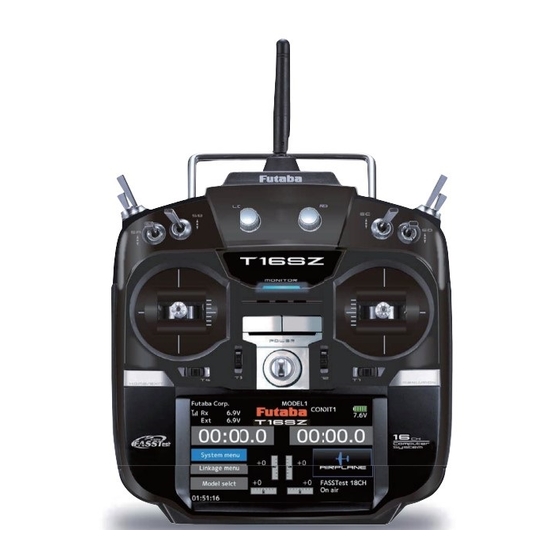
- Page 13 ● Monitor LED ● Antenna ● Carrying handle ● Dial LD.RD ● Switch ● Switch SA.SB.SE.SF SC.SD.SG.SH ● Slide lever ● Slide lever ● Stick ● Stick ● Power Switch ● Digital trim T1-T4 ● Hook ● HOME/EXIT Button ● U.MENU/MON. Button (User menu/Servo monitor) ● Battery cover ● Color LCD display Touch Panel The panel displays shown in this manual may vary from your own, depending upon your model type. Panel displays may also vary as a result of version upgrades or other changes.
- Page 14 If you fly with your Low power transmitter facing the model at the angle shown in the illustration, High power High power bend the antenna 90 degrees. Do not fly your model with the antenna's tip pointing in its direction. CAUTION The antenna can be rotated 180 degrees and angles 90 degrees. Forcing the antenna further than this Please do not grasp the transmitter's can damage it. The antenna is not removable. antenna during flight. ...
- Page 15 SF : 2 positions; Alternate; SH : 2 positions; Momentary; Long lever Long lever SE : 3 positions; Alternate; SG : 3 positions; Alternate; Short lever Short lever SA : 3 positions; Alternate; SD : 3 positions; Alternate; Short lever Short lever SB : SC : 3 positions; Alternate; 3 positions; Alternate; Long lever Long lever *Self retum 2 positions 3 positions Alternate Momentary < Before Use >...
- Page 16 analog input. knob reaches the center position. *You can use each setting screen of the mixing functions to select volumes and define the direction of movement. *You can select a slide lever and set the movement direction on the setting screen of mixing functions. <...
- Page 17 referencing the LCD screen. *You can select the trim step amount and the display unit linkage menu. *Example Stick Mode2 ◆When the airplane goes up while the ◆When the airplane dives while the elevator stick is neutral. elevator stick is neutral. ◆Elevator trim to up ◆Elevator trim to down Elevator Neutral Elevator Neutral Elevator Down Elevator Up ◆Adjust so that the airplane flies level. < Before Use >...
- Page 18 ③ Connect the battery connector. ① A side battery cover is opened. Battery cover ④ Close the battery cover completely. ② Install the battery into the transmitter. This 2P connector connects HT5F1800B to the transmitter. NiMH Battery < Before Use >...
- Page 19 1.Plug the transmitter cord of the special will be shown the next time when you turn on the charger into the charging jack on the side of power of the transmitter. Do not use the transmitter the transmitter. as it is. Send it to the Futaba service center. 2. Plug the charger into an AC outlet. 3. Check that the charging LED lights. WARNING Never plug the charger into an outlet other than the indicated voltage.
- Page 20 part of the front of a T16SZ. Power Switch Power Switch Power Switch Throttle Stick Low Right or Left Long Push Right and Left Push Right or Left Long Push Tap this to stop the alarm a n d R F s i g n a l . O n l y p a n e l Warning alarm screen operation is active, the ...
- Page 21 Tapping the settings buttons for each value on the settings screen data. will cause value input buttons to appear at the top of the panel. be careful so that you don't scratch the Touch Panel Pressing and holding a value will anything on the panel. return it to its default setting. Value input buttons display at the plastic panel due to environmental changes such top of the panel. problems. pixels hold lighting. Moreover, some pixels go out. And a screen may flicker.
- Page 22 Temporarily activating this function makes it impossible to change data by mistakenly touching keys How to lock 1. The home screen is displayed. 2. Press the HOME/EXIT button for about 1 second. "Key mark" is displayed and the keys disabled. Panel lock HOME/EXIT Press and hold How to unlock...
- Page 23 *Example Stick Mode2 < Before Use >...
- Page 24 *Example Stick Mode2 A general model example. (There is also a different operational model.) Roll Axis Control Pitch Axis Control Right roll Nose Up The right aileron is up. Elevator stick The left aileron Aileron stick is down. To the right (moved to the bottom) Elevator is Level flight Level flight Neutral Neutral Elevator is down. Left roll The right Elevator stick Aileron stick aileron is Nose Down down. The left aileron DOWN To the left is up. (moved to the top) Yaw Axis Control Throttle Control High throttle Nose Right Throttle stick Rudder stick HIGHT To the right (moved to the top) A rudder is ...
- Page 25 *Example Stick Mode2 A general model example. (There is also a different operational model.) Roll Axis Control Pitch Axis Control Right roll Nose Up Elevator stick Aileron stick To the right (moved to the bottom) Level flight Level flight Neutral Neutral Left roll Elevator stick Aileron stick Nose Down DOWN To the left (moved to the top) Yaw Axis Control Throttle /Pitch Control Nose Right Throttle stick Rudder stick Rise HIGHT To the right (moved to the top) Pitch Up High Hovering Throttle stick Neutral MIDDLE (neutral) Middle Straight Descent Pitch Down Rudder stick Throttle stick...
- Page 26 *Example Stick Mode2 A general model example. (There is also a different operational model.) Roll Axis Control Pitch Axis Control Right roll Nose Up Right slide Elevator stick Aileron stick Back slide To the right (moved to the bottom) Hovering Level flight Hovering Level flight Neutral Neutral Left roll Nose Down Left slide Elevator stick Aileron stick Front slide DOWN To the left (moved to the top) Throttle Control Yaw Axis Control Nose Right Throttle stick Rudder stick Rise HIGH To the right (moved to the top) Hovering Hovering Level flight Throttle stick Neutral MIDDLE (neutral)
- Page 27 *In case of mode 1 2. Next, using a hand, remove the transmitter's side cover (rubber). When using Mode 1, you will need to remove the side cover to expose the tension screw. Lever head Lever head head "A" counter-clockwise. The lock will be released.
- Page 28 SD and SDHC cards (SD:32MB-2GB SDHC:4GB-32GB). Saving model data and update files (released When you have a problem of saving or reading from Futaba) into the SD card, you can use those card. *We are not responsible for, and offer no compensation for, electronics stores.
- Page 29 not use excessive force when inserting. -When an SD card is installed in the T16SZ transmitter, a folder called "Futaba" is cre- folder stores the telemetry log data. -The telemetry log data recorded on the SD card can be converted to CSV format by the telemeter log converter released on our home page.
- Page 30 When using an S.BUS servo and telemetry sensor, connect them both here. Earphone Connecting a stereo headphone to this plug, the Plug speech information of telemetry can be heard. Charge Plug This is the connector for charging the NiMH battery HT5F1800B that is installed in the transmitter.
- Page 31 Before using the receiver, be sure to read the DANGER Don't attach a connector as shown in the preceding illustration. *It will short-circuit if connected in this way. A short circuit across the battery terminals may cause abnormal heating, fire and burns. WARNING S.BUS2 connectors Don't connect an S.BUS servo / gyro to S.BUS2 connector. Connector "1 through 6": outputs for the channels 1 LED Monitor through 6 This monitor is used to check the CH mode of the receiver.
- Page 32 DANGER Don't touch wiring. * There is a danger of receiving an electric shock. Do not short-circuit the battery terminals. * A short circuit across the battery terminals may cause abnormal heating, fire and burns. Please double check your polarity ( + and − ) when hooking up your connectors. * If + and − of wiring are mistaken, it will damage, ignite and explode. 1. Press and hold down the Link/Mode button Don't connect to Extra Voltage before turning on a receiver power supply. 2. Turn the receiver on while holding down the Link/Mode button. When the LED begins to blink green/red the button may be released.
- Page 33 *Must be kept as straight as possible. Antenna Coaxial cable R7008SB Receiver This is not a critical figure, but the most To obtain the best results of the diversity important thing is to keep the antennas away from each other as much as possible. instructions: Larger models can have large metal 1.
- Page 34 Wood screw 2.3-2.6mm nut washer Rubber Rubber grommet grommet WARNING Brass eyelet Brass eyelet Servo mount Connecting connectors Servo mount 2.3-2.6mm screw Be sure to insert the connector until it stops at the deepest point. (Airplane/Glider) (Helicopter) How to protect the receiver from vibration and water To prevent the servo lead cable from being Wrap the receiver with something broken by vibration during flight, provide a soft ...
- Page 35 number of servos used. S.BUS Glider usage example Receiver: R7008SB Servo: S3174SV×9 ( Optional ) HUB×4 ( Optional ) Throttle servo: BLS173SV ( Optional ) Battery: FR2F1800 ( Optional ) S.BUS Aerobatic plane usage example Switch Receiver: R7008SB Aileron servo: BLS174SV×2 ( Optional ) HUB×3 ( Optional ) Rudder Servo: BLS175SV×1 ( Optional ) Elevator servo: BLS173SV×2 ( Optional ) < Before Use >...
- Page 36 ●S.BUS Servo Receiver Optional Parts ●6-Terminal box (TB16PP) ●Hub(Another power supply) Orange ●Hub Green ●When separate power supply used WARNING Power supply Please make sure that you use a battery that can deliver enough capacity for the number and kind of servos used. Alkaline batteries cannot be used. S.BUS Gyro CGY750 Connection example Receiver < Before Use >...
- Page 37 When using the S.BUS2 port, an impressive array of telemetry sensors may be utilized. S.BUS2 TABLE S.BUS2 S.BUS Servo Servo Receiver port Telemetry sensor S.BUS Gyro S.BUS2 Gyro S.BUS ○ ○ × S.BUS2 × (※) ○ ○ (※)Don't connect S.BUS Servo, S.BUS Gyro to S.BUS2 connector. S.BUS servos and gyros and S.BUS2 servos and gyros must be used in the correct receiver ports.
- Page 38 S.BUS/S.BUS2 servos or a telemetry sensor can be connected directly to the T16SZ. Channel setting and other data can be entered for the S.BUS/S.BUS2 servos or sensors. 2. Turn on the transmitter power. 3. Call the setup screen. Servo: System Menu Sensor: Linkage Menu Sensor 4.
- Page 39 BASIC OPERATION This is the Home screen and descriptions of its menus. Use your finger to operate the touch screen. Battery voltage for receivers Condition name Battery Indicator • In FASSTest/T-FHSS mode, it is • The condition name • When the battery voltage displayed.
- Page 40 Each transmitter has an individually assigned, unique ID code. In order to start operation, the receiver must be linked with the ID code of the transmitter to which it is being paired. Once the link is made, the ID code is stored in the receiver and no further linking is necessary unless the receiver is to be used with another transmitter.
- Page 41 setup a "Rx1" and "Rx2" in the "dual" mode. 9. ACT will be chosen if telemetry is used. It is INH when not using it. *Telemetry function cannot be used for the 2nd receiver. → FASSTest18CH *Telemetry function cannot be used for the dual receiver.
- Page 42 ◆ When the receiver has the transmitter's ID in memory, a link is established and normal operation is allowed. ◆ When the transmitter has the receiver's ID in memory, a link is established and telemetry functions are usable. The transmitter stores receiver IDs by model; thus, if it does not have a particular receiver model ID stored in memory or has a different receiver ID stored, telemetry functions will be unusable. However, the device is operable as long as the receiver has the transmitter's ID stored in memory. Link of model 1 Model 1 → Model 2 Model 1: Receiver ID: xxxxxx1 Device is operable if receiver Model 2: Receiver ID: --------- has transmitter's ID stored in Model 3: Receiver ID: --------- memory Link Tx ID: xxxxxx2 Rx ID: xxxxxx1 Tx ID: xxxxxx2 Telemetry functions unusable because stored Model 2 does not have receiver's ID Operable stored in memory. Transmitter switched to Model 2 and ...
- Page 43 transmitter incorporates a system that reduces its power output and allows you to perform such a range check. During this mode, the RF power output is reduced so the range test can be performed. In addition, when 1. While pushing "U.MENU/MON." button. this mode is activated the right LED on the front of the transmitter starts blinking and the transmitter gives users a warning with a beeping sound.
- Page 44 MODEL BASIC SETTING PROCEDURE Initial setting assigns 1 model to the T16SZ transmitter. The Model Select function is used to add models and to select models which are already set. the direction with the Reverse function of the Linkage menu. The data for up to 30 models can be saved to the transmitter.
- Page 45 This function is used when an air brake is necessary when taking off or diving, etc. offset amount can be activated by a switch. The offset amount of the aileron, elevator, and flap servos can be adjusted as needed. Also the speed of the aileron, elevator, and flap servos can be adjusted.
- Page 46 match the fuselage used. Default setting assigns 1 model to the T16SZ. To add new models or to call a model already set, use the Model per model. select function. The Condition select function automatically allocates This is convenient when calling a model after registering the model names in advance.
- Page 47 Connect the throttle rudder, aileron, elevator, pitch, and other servos in accordance with the kit instruction manual. For a description of the connection method, see "Servos connection by model type". Note: The channel assignment of the T16SZ is different from that of our existing systems. (The channel assigned to each function can *If any interactions are noticed, for a description of the be checked at the Function menu of the...
- Page 48 º as standard. º *If throttle hold is necessary, please refer to the Throttle hold function. The high side pitch setting is less than idle up 1. The standard is +8º. Throttle cut provides an easy way to stop the engine, by flipping a switch with the throttle stick at idle.
- Page 49 The T16SZ transmitter channels are automatically assigned for optimal combination according to the type selected with the Model type function of the Linkage menu. The channel assignment (initial setting) for each model type is shown below. Connect the receiver and servos to match the type used. *The set channels can be checked at the Function screen of the Linkage menu.
- Page 50 1AIL 2AIL 2AIL+1FLAP 2AIL+2FLAP 2AIL+4FLAP 4AIL+2FLAP 4AIL+4FLAP Airplane Glider Airplane Glider Airplane Glider Airplane Glider Airplane Glider Airplane Glider Airplane Glider Aileron Aileron Aileron Aileron Aileron Aileron Aileron Aileron Aileron Aileron Aileron Aileron Aileron Aileron Elevator Elevator Elevator Elevator Elevator Elevator Elevator Elevator...
- Page 51 2AIL 2AIL+1FLAP 2AIL+2FLAP 2AIL+4FLAP 4AIL+2FLAP 4AIL+4FLAP RX Airplane Glider Airplane Glider Airplane Glider Airplane Glider Airplane Glider Airplane Glider Aileron Aileron Aileron Aileron Aileron Aileron Aileron Aileron Aileron Aileron Aileron Aileron AUX4 AUX4 AUX4 AUX4 AUX4 AUX4 Aileron2 Aileron2 Aileron2 Aileron2 Aileron2 Aileron2...
- Page 52 2AIL 2AIL+1FLAP 2AIL+2FLAP 2AIL+4FLAP 4AIL+2FLAP 4AIL+4FLAP RX Airplane Glider Airplane Glider Airplane Glider Airplane Glider Airplane Glider Airplane Glider Aileron Aileron Aileron Aileron Aileron Aileron Aileron Aileron Aileron Aileron Aileron Aileron Rudder2 Rudder2 Rudder2 Rudder2 Rudder2 Rudder2 Aileron2 Aileron2 Aileron2 Aileron2 Aileron2 Aileron2...
- Page 53 H-4/H-4X Swash All other Aileron Aileron Elevator Elevator Throttle Throttle Rudder Rudder Gyro Gyro Pitch Pitch Governor Governor Elevator2 Governor2 Gyro2 Gyro2 Gyro3 Gyro3 Governor2 Needle Needle AUX5 AUX4 AUX3 AUX2 AUX1 H-4/H-4X Swash All other Aileron Aileron Elevator Elevator Throttle Throttle Elevator2 Rudder Pitch Pitch Gyro...
- Page 54 Multicopter Aileron Elevator Throttle Rudder Gyro Gyro2 Gyro3 Camera TILT Camera PAN Camera REC Mode AUX5 AUX4 AUX3 AUX2 AUX1 SW SD SW SD SW SA < Model Basic Setting Procedure >...
- Page 55 SYSTEM MENU The System menu sets up functions of the transmitter. This does not set up any model data. [Display]: Display adjustment. [Sound volume]: Adjust the volume of: Other sound, Warning, Voice [System timer]: Resets the system timer. [H/W setting]: Stick mode selection (Mode 1 - Mode 4 ). J1-J4 sticks correction can be performed. [Battery] : ...
- Page 56 Display The following LCD screen adjustments: Backlight max. brightness adjustment Touch calibration becomes darker. Backlight min. brightness adjustment becomes darker. *In ordinary operation, this calibration is not necessary. If *It cannot be made brighter than Backlighting brightness you notice the Touch Panel is not functioning correctly after adjustment.
- Page 57 Sound volume This function can set the volume of "Other sound," "Warning," and "Voice," respectively. The respective volume control Sound volume Setting method ▲▲ ▲ ▼▼ ▼ *If you tap " ", the volume will increase. If you tap the ▲ " ", the volume will decrease.
- Page 58 But, it isn't changed until data is reset. the center of a stick should arise after prolonged use. To change the mode the stick ratchet must be changed. Request that this be done by Futaba Service. (Charged MODE1 MODE2 MODE3...
- Page 59 Battery Select the battery alarm voltage according to the battery to be used. It isn't indicated in case of manual setting. Battery type change : LiFe(2cells) → NiMH(5cells) → Manual setting When choosing manual setting, the numerical value can be input. It's dangerous to set it manually in the low voltage. Auto power off time setting Vibrator Types Type 1 Type 2 *When the time the transmitter is inactive reaches Type 3 the set time, the power is turned off automatically.
- Page 60 S.Bus servo An S.BUS(2) servo can memorize the channel and various settings you input. Servo setting can be performed on the T16SZ screen by wiring the * With some S.BUS(2) servos, there are some functions which cannot be used. If a function cannot be used, the display screen will change.
- Page 61 S.BUS Servo Description of each parameter's function *There are functions that can and cannot be performed according to the servo type. • ID Displays the ID of the servo whose parameters are to be read. It cannot be changed. • Channel Channel of the S.BUS system assigned to the servo.
- Page 62 • Boost ON/OFF OFF : It is the boost ON at the time of low-speed operation.(In the case of usual) ON : It is always the boost ON.(When quick operation is hope) • Damper The characteristic when the servo is stopped can be set. When smaller than the standard value, the characteristic becomes an overshoot characteristic.
- Page 63 Information This function registers the T16SZ user name The Information screen displays the T16SZ and the language displayed at proportional can be system program version information, SD card changed. (memory size, card free size) information. *If an SD card is not inserted, no memory card information Telemetry numerical values can be displayed in will be displayed.
- Page 64 LINKAGE MENU The Linkage menu is made up of functions which perform model addition, model type selection, end point setting, and other model basic settings. [Servo monitor]: Displays the servo test and operation position [Model select]: Model addition, call, deletion, copy, model name setting [Model type]: Model type, wing type, tail type, swash type, selection [Servo reverse]: Servo direction reversal [End point]: Servo basic rate adjustment and limit setting...
- Page 65 Servo monitor This is used for testing servo movement. In order to prevent any potential difficulties, the servo test function will be inoperable, or the Servo Test function is not operational if the neutral position of a servo horn. mode. Test mode change : OFF →...
- Page 66 Model select This function is used to load the settings of the screen. The Copy function is used to copy one set The settings may be selected from either the of model data into a second memory within the transmitter and the SD card. It may be used for getting a head-start on setting up models with memories are available in the transmitter.
- Page 67 Model call Model deletion (The model currently selected cannot be deleted.) Blue model would be deleted. Blue model was deleted. < Linkage menu >...
- Page 68 Model name change Model copy Current model (green) is chosen (blue). Current model (green) is chosen (blue). When you are done renaming, tap Model name. Completion of rename WARNING add new copied model Never launch the Model Selection function while the engine is starting or the motor drive wiring is connected. *If there is no model with the same name in the copy ■Careless spinning of propellers or rotors is ...
- Page 69 Model type for airplanes. Eight swash types are available for helicopters. Seven types of main wings and three types of tail wings are available for gliders. model type are set in advance at the factory. ( The display screen is an example. The screen depends on the model type.) Model type selection →...
- Page 70 Set the type you choose by tapping. Airplane/Glider : Choose the Helicopter : Choose the wing type and tail. swash type. < Linkage menu >...
- Page 71 Servo Reverse Servo Reverse changes the direction of an model memory, hook ups, and radio function. movement. WARNING For CCPM helicopters, be sure to read the section on Swash AFR before reversing any servos. Before a flight, always check that your With CCPM helicopters, always complete your model's servo operation, the direction ...
- Page 72 End point The End point function adjusts the left and right servo throws, generates differential throws, and will correct improper linkage settings. 30 〜 30 〜 140% 140% Travel rate Limit point Next page Ch7-16 Tap the values you wish to adjust and value input buttons will appear on-screen.
- Page 73 Servo speed The Servo speed setting is used to set the servo delay for each channel, from channel l to channel channel. to slow down servo position changes. The Servo (First) 0 〜 27 (Slowly) Servo speed setting Sub-trim The Sub-Trim function is used to set the servo and pushrods are hooked up.
- Page 74 Function DG1, DG2 (switch channels) you will find that the optimized combinations of servo output channels and functions have been already preset. If you would like, on the function- between servo output channels and input controllers setting screen of the linkage menu, you can freely change combinations of servo output channels, Channel restrictions by a System Type multiple servo output channels such as assigning...
- Page 75 Trim change H/W reverse This function reverses the operation signal of the sticks, switches, trim levers, and knobs. signal, but does not change the display of the long as there is no special reason to use the reverse mode. The Motor function is used when switching the motor ...
- Page 76 Fail safe The Fail safe function is used to set up positions moves to a position you did not command, land at that the servos will move to in the case of radio once and check your receiver battery. lost and when receiver battery voltage becomes low. Defines servo position when signals are lost and You may set either of two positions for each when receiver battery voltage becomes low.
- Page 77 System type System Type selection Dual receiver function (only FASSTest 18CH ) Two receivers are recognized individually by ID setting function is used, by setting the first as as Two sets of receivers can be used as a set in the *If you change the System type, other model data is not reset.
- Page 78 The example for choosing System Type -Want to use a -Want to use an miniature receiver T-FHSS system -Response speed has -Want to use a -Want to use an for indoor planes receiver priority over number previously used S-FHSS system of channels receiver as is -Want to use a large miniature receiver number of telemetry -Telemetry requires functions only the current receiver battery FASST 7CH -Want to use more channels -Want to use a large number S-FHSS FASST MULTI of telemetry functions T-FHSS Air R617FS FASSTest 12CH R3006SB R2006GS R6004FF R608FS R3008SB R2106GF R616FFM...
- Page 79 Trim setting This function adjusts the digital trim's control When the flight conditions are set, the trim operation can be coupled with any of the conditions selected through combination mode. Control step amount setting Separate/combination mode selection [Comb.] [Separ.] ▲▲ ▲ ▼▼ ▼...
- Page 80 Throttle cut Throttle cut provides an easy way to stop the idle. The action is not functional at high throttle to and direction must be chosen, as it defaults to " − Tapping this will change − " . INH to either OFF or ON and activated. The yellow line is the cut position. When This ...
- Page 81 Idle down The Idle down function lowers the engine's idle The action is not functional at high throttle to avoid Tapping this will change direction must be chosen, as it defaults to " −− " . INH to either OFF or ON and activated. T h i s i s t h e i d l e d o w n throttle position. Tapping this will display value input ...
- Page 82 Swash ring This function limits the travel of the swash plate to prevent linkage damage as the aileron and setting. Setting the function to "ACT" will display the swash ring and [Rate] The movement range percentage. display shows control input for elevator and aileron direction. The marker represents the stick's position. Swash ring setting procedure *The movement area monitor shows the current aileron and elevator values and limit ranges by the yellow circle.
- Page 83 Swash Neutral Point Mixing Rate At your linkages, if the servo horn deviates from a perpendicular position at neutral, the linkage the tendency of the swash-plate for each control. compensation functions in this menu may not compensate effectively. To correct this use the PIT to AIL, PIT to ELE, AIL to PIT, ELE to AIL, neutral point function.
- Page 84 Linkage correction setting procedure Neutral point setting procedure rate. *Adjusting the servo horn so that the neutral point position is *This function compensates for elevator interference by aileron operation or aileron interference by *The neutral point is displayed on the screen. *The left and right sides can be adjusted separately.
- Page 85 Stick alarm Tapping this will change INH to ON and activated. If the throttle stick reaches the yellow l i n e , a n a l a r m w i l l sound. T h i s i s t h e c u r r e n t This ...
- Page 86 Timer The Timer function may be set for Each timer may be set for count-down or count up any desired time, i.e. engine run time, operation with a target time. specified times for competitions, etc. If a target time is set and the timer reaches the set time, a Two independent timers are provided buzzer sound for each count is generated.
- Page 87 Integration Timer of the throttle stick. When the throttle stick is raised for faster speed, the speed of the timer usually throttle is positioned at low end, the timer's progress stops. It's possible to set it in the time which When a throttle stick is the high side, the speed of the ...
- Page 88 Function name Function name change method < Linkage menu >...
- Page 89 Telemetry system This screen displays and sets the various information from the receiver. An alarm and vibration can be in the aircraft can be reported by an alarm. ● This function can only be used in the FASSTest18CH mode and T-FHSS mode. The FASST/S-FHSS mode cannot use telemetry.
- Page 90 Home display HOME/EXIT is pushed 4 of telemetry data is displayed *Be aware that pressing and holding this activates the key lock Y o u c a n c h o o s e which type of sensor t o d i s p l a y f o r f o u r displays. Tap the sensor ...
- Page 91 Sensor [What is a slot?] This screen registers the telemetry sensors used sensors are with the transmitter. When only one of a certain classified in units called “slot”. There are slots from type of sensor is used, this setting is unnecessary No.
- Page 92 This page is set when using multiple telemetry sensors of the same type. Sensor:Reload When using multiple sensors of the same type the sensors must be registered in the transmitter. the following procedure. The ID of each sensor is Hub registered in the transmitter. Hub Hub *It is not necessary to carry out multiple battery connections like Reading all the sensors to be used Sensor : Register...
- Page 93 This page is set when using multiple telemetry sensors Sensor : Change slot of the same type. This procedure changes the slot number of one registered sensor. Receivers Battery sensor is changed, the sensor cannot be used. Sensor slot change + ( WARNING ) Do not disconnect or turn transmitter power OFF while telemetry sensor data is being saved. Sensor save data will be lost, resulting in malfunction.
- Page 94 Telemetry This screen displays your choice of data from the receiver. Also warnings can be activated regarding the T a p p a g e b u t t o n t o advance to next page. ( The number of pages changes with the number ...
- Page 95 Telemetry: Receiver [Battery] In this screen, the battery voltage of a receiver is displayed. *Only receiver voltage and EXT voltage can be used in If it becomes higher or lower than the settin, an alarm and/or vibration will alert you. functions. Receiver battery voltage ...
- Page 96 Telemetry: Receiver [Ext. battery] *CA-RVIN-700 must be installed in the aircraft. The EXT-VOLT screen will display the data from You will be alerted by an alarm or vibration if In order to use this function, it is necessary to *Only receiver voltage and EXT voltage can be used in voltage of EXT-battery.
- Page 97 Telemetry : Temperature *A temperature sensor must be installed in the aircraft. Temperature is a screen which displays/sets up the temperature information from an optional *Only receiver voltage and EXT voltage can be used in temperature sensor. functions. If it becomes higher or lower than the setting, an alarm and/or vibration will alert you. Temperature Max. and min. values s i n c e ...
- Page 98 Telemetry : RPM Sensor *An rpm sensor must be installed in the aircraft. The RPM Sensor screen is used to set up an optional rpm sensor and display the rotation information it transmits. *Only receiver voltage and EXT voltage can be used in functions. If it becomes higher or lower than the setting, an alarm and/or vibration will alert you.
- Page 99 Telemetry : Altitude *An altitude sensor or GPS sensor must be installed in the aircraft. Altitude is a screen which displays / sets up the altitude altitude from atmospheric pressure. Atmospheric pressure will get lower as you go up in altitude. Using this, the sensor will estimate the altitude. Please understand that an alarm.
- Page 100 Telemetry : Altitude [Variometer] *An altitude sensor or GPS sensor must be installed in the aircraft. VARIO is a screen which displays / sets up the variometer information from an optional altitude for ascent and descent. Additionally, depending upon the rate of climb or descent, the tones vary to indicate whether or not the airplane is climbing or descending at a rapid rate.
- Page 101 Vario Melody Setting Tap the [Set] button Current variometer *These settings can be made for each sensor. Next page Range Deadband Setting range: Setting range: Setting range: 〜 Initial value: Setting range: 〜 〜 〜 Initial value: Initial value: Initial value: Offset Fixed melody Range↑...
- Page 102 Delay Setting range: , , , Initial value: *This parameter is effective to all variometers. Actually Variometer 0.0m/s 1.0m/s 3.0m/s 4.0m/s 2.0m/s -1.0m/s Output Vario Melody 0.0m/s 1.0m/s 3.0m/s 4.0m/s 2.0m/s -1.0m/s Delay time 1.0s < Linkage menu >...
- Page 103 Telemetry: Voltage [Battery] *SBS-01V must be installed in the aircraft. In this screen, the battery voltage is displayed. In this screen, the battery voltage of a receiver is In order to use this function, it is necessary to displayed. ⇔ If it becomes higher or lower than the settin, an ⇔...
- Page 104 Telemetry: Voltage [Ext. battery] *SBS-01V must be installed in the aircraft. In this screen, the EXT battery voltage is displayed. In order to use this function, it is *Only receiver voltage and EXT voltage can be used in ⇔ ⇔ functions. battery connected to two lines is displayed on EXT- VOLT.
- Page 105 Telemetry : GPS [Distance] *A GPS sensor must be installed in the aircraft. The Distance screen displays and sets altitude and connect the sensor in accordance with the sensor instruction manual. aircraft to be read by the transmitter. When the aircraft flies inside or outside the set distance, an *Only receiver voltage and EXT voltage can be used in alarm and vibration alerts the pilot.
- Page 106 First, the set of a reference is required. Setting a "too close" alarm distance Setting a "too far" alarm distance ≧ *When the screen is tapped for one second, the rate is reset to the initial value. ≧ *When the screen is tapped for one second, the rate is reset to the initial value.
- Page 107 Telemetry : GPS [Speed] *A GPS sensor must be installed in the aircraft. The speed screen displays and sets the speed data from an and connect the sensor in accordance with the sensor instruction manual. *Only receiver voltage and EXT voltage can be used in air speed. Consequently, with a head wind, the displayed speed decreases and with a tail wind, the displayed speed increases.
- Page 108 Telemetry : GPS [Altitude, Variometer, Position] *A GPS sensor must be installed in the aircraft. The Altitude, Variometer, Position screen *Only receiver voltage and EXT voltage can be used in functions. and connect the sensor in accordance with the sensor instruction manual. Max. and min. values s i n c e t h e p o w e r was ...
- Page 109 Telemetry : Servo sensor [Current] *Servo sensor must be installed in the aircraft. in-flight current, operating angle, and internal If you forget to connect the servo wiring during fuselage assembly, or the servo was disconnected, an alarm can be activated at the transmitter. Tap here and go to the Servo 2 settings page. (Display and settings content is the same as Servo 1.) Max. and min. values Tapping this will s i n c e ...
- Page 110 Telemetry : Servo sensor [Temperature] [Angle] *Servo sensor must be installed in the aircraft. ● Temperature ↑ An upward arrow indicates the alarm will sound when the temperature reaches above your set value. ↓ A downward arrow Sets the temperature indicates the alarm on which the alarm will sound when the operates. temperature reaches below your set value. Alarm is chosen from Buzzer, Voice, and Inhibit. Vibrator choices are Initial value: ↑ 115℃↓ -10℃ type1-3, and Inhibit. Allows Speech to be Adjustment range -10℃...
- Page 111 Telemetry : Current sensor [Current] *Current sensor must be installed in the aircraft. drive battery all at the same time. Tapping this will take you to the settings screen for the current alarm Max. and min. values since the power Tapping this will take you to was turned ON will the settings screen for the display. voltage alarm Tapping this will take you to the settings screen for the consumption capacity alarm The consumption capacity is indicated. It isn't the present battery capacity. ◆ Alarm setting ↑ An upward arrow indicates the alarm will sound when the current reaches above Sets the current on your set value. which the alarm ↓ A downward arrow operates. indicates the alarm will sound when the current reaches below "Vibrator" type your set value.
- Page 112 ■ Extension FLD: Log data file *When copying or moving a log file, always select both the .FLI file and .FLD file. Log files can be converted to CSV format by using the telemetry log converter available at the Futaba website. ■ Notes ◇...
- Page 113 Telemetry Alarm Duration and Repeat time The repeat time and duration time for the telemetry alarm (buzzer, vibration and speech) can be set. Duration is not displayed when Repeat is INH. Duration Repeat It is an alarm output time. It is a repeat time of an alarm Setting range:1 s 〜 30 s output. Initial value:INH Setting range:INH,1 s 〜 240 s Duration value has to be less than Initial value:INH repeat value. Duration time is extended when the other alarm event occurs.
- Page 114 Trainer Note: This trainer system can be used in the following instructor to choose which channels and operation manner: modes can be used in the student's transmitter. The function and rate of each channel can be set. transmitter, if the channel order is different, it is necessary to match the channel order before using this The training method can also be matched to the function.
- Page 115 When using at the student side When using at the teacher side *When changing the mode, tap to the item you want to *When changing the mode, tap to the item you want to the mode. the mode. item, call the switch setup screen and set the desired switch *The switch mode can also be selected when setting the [Alternate] is selected, the trainer function is alternately turned on and off each time the switch is operated.
- Page 116 Trainer student channel setting function In training mode, the instructor's transmitter can pick up the student's signal on both the "Function" two transmitters to connect even if the student and instructor have set up their transmitters differently. the signal of the same channel of the student's transmitter is *The setting above allows setting of the servo throw relative to the amount of student side operation when [MIX] or *When the value is tapped, the rate is reset to the initial value.
- Page 117 Warning setting The settings can be changed "Vibrator" type individually. When set to If the following types are selected, the transmitter [Inhibit], a warning is not will vibrate during the warning. displayed at power ON. Type 1 Type 2 Type 3 WARNING It is extremely dangerous to unnecessarily inhibit essential warnings. ■Careless spinning of propellers or rotors poses a danger of serious injury or death. < Linkage menu >...
- Page 118 User menu setting *Any change made to data entered from the User menu or from the normal method of use are the same. Changes made System, Linkage, and Model. Also, you can in either way are saved into the transmitter memory. create a personalized User menu that can include all of the menus that you use most often.
- Page 119 Data reset This function is designed to allow you to reset Model menu setting: selected portions or all of the settings saved in Resets all the functions in the Model menu the active model memory. You may individually choose to reset the following sets of data: All model setting: Trim (All condition): Resets all Linkage and Model menu functions...
- Page 120 MODEL MENU (Common functions) This section describes the AFR, program mixing, Select function to add flight conditions. (Up to 8 and other functions common to all model types. conditions can be used) Note: The T16SZ is designed so that the airplane and Before setting the model data, use the Model glider model types are compatible with aircraft of Type function of the Linkage menu to select the...
- Page 121 Flight condition's addition, deletion, copy, condition renaming, Condition select and condition delay can be set. [All model types] when there are sudden changes in the servo The functions in the Model menu can be used by positions and when there are variations in switching the settings of up to 8 flight conditions the operating time between channels during condition switching can be suppressed.
- Page 122 Currently selected condition name The ON/OFF switch of Conditions List condition is chosen. 1 . S e l e c t t h e c o n d i t i o n b y appears. tapping the condition you 2. Select the condition by tapping the button List. of the copy source conditions.
- Page 123 The angle and curve of each operation function can be set. [All model types] AFR function is used to adjust the throw and operation curve of the stick, lever, and switch the maximum throw. When mixing is applied from one channel to another channel, both channels can be adjusted at the same time by adjusting the Rate operation rate through the AFR function.
- Page 124 Dual rate 100% D/R curves which can be switched by switch, etc. can be added. The curve can be adjusted by the AFR function. condition. call the setup screen shown below. The ON/OFF switch of dual rate is chosen. Activate the D/R function When the function select button by tapping the [INH] . is tapped, a selection screen appears. ...
- Page 125 Program. mixes mixings can be used for each condition. [All model types] Offset-type mixing applies a fixed offset or Programmable mixing may be used to correct undesired tendencies of the aircraft, and it may also preset to the programmed channel servo operation and may control up to four circuits simultaneously.
- Page 126 button on the screen. Activating functions for only the selected *When mixing includes master side trim, set the Trim button conditions: to [ON]. When mixing does not include master side trim, set the Trim button to [OFF]. mode. *Each time this button is pressed, it toggles between [ON] *Each time the button is tapped, it toggles between the Gr and [OFF].
- Page 127 MODEL MENU (Airplane/Glider/Multicopter functions) The dedicated mixes, etc. usable when airplane condition by switch or stick position, use the or glider model type is selected are displayed in this Model menu functions section. First use (Up to 8 conditions can be used) Note: The T16SZ is designed so that the airplane and the Model type function of the Linkage menu to glider model types can handle aircraft of the same...
-
Page 128: Table Of Contents
Camber mixing This mix adjusts the camber and corrects the This function is used when airbrakes are necessary when landing or when diving, etc. during flight. elevators. [Airplane/glider, 2 ailerons or more] [Airplane, general] This mix is used to correct operation of the airbrakes (spoilers) when landing. -
Page 129: Ail 3
[Airplane/glider, 2 ailerons or more] Aileron differential The left and right aileron differential can be adjusted independently. The differential rate can also be adjusted according to the flying state by AIL1 AIL 2 (Main Aileron) (Main Aileron) AIL 3 AIL 4 (Chip Aileron) (Chip Aileron) menu and call the setup screen shown Currently selected condition name below. - Page 130 [Corresponding model type]: Airplane/ Flap setting The up/down travel of each flap (camber flaps: FLP1/2, brake flaps: FLP3/4) can be adjusted independently at each servo according to the wing type. FLP 4 FLP 3 (Brake Flap) offset (Brake Flap) FLP 1 FLP 2 (Camber Flap) (Camber Flap) call the setup screen shown below. Currently selected condition name Condition group/single ...
-
Page 131: Ail1 Flp
[Corresponding model type]: Airplane/ AIL → Camber flap This mix operates the camber flaps (FLP1/2) in the aileron mode. When the aileron stick is manipulated, the ailerons and camber flaps perform aileron operation simultaneously and the operation characteristic of the roll axis is FLP 1 FLP 2 (Camber Flap) -
Page 132: Flp 3
[Corresponding model type]: Airplane/ AIL → Brake flap This mix operates the brake flaps (FLP3/4) in the aileron mode. When the aileron stick is manipulated, the aileron and brake flaps perform the aileron operation simultaneously FLP 4 FLP 3 (Brake Flap) (Brake Flap) and the operation characteristic of the roll axis is improved. -
Page 133: Rudder (Aileron 5)
[Corresponding model type]: Aileron → Rudder Airplane/glider, general Use this mix when you want to mix the rudders with aileron operation. AIL1 AIL 2 (Main Aileron) (Main Aileron) AIL 3 AIL 3 (Chip Aileron) (Chip Aileron) RUDDER 2 RUDDER 1 Winglet Winglet ( ) ( ) at Flying wing at Flying wing V-TAIL RUDDER 2 RUDDER RUDDER model menu and call the setup Currently selected condition name screen shown below. - Page 134 [Corresponding model type]: Airplane/glider, 2 ailerons or more Elevator → Camber This function is used when you want to mix the be increased. menu and call the setup screen shown Currently selected condition name below. Elevator → Camber ● Mixing curve setting (For a description of the setting method, see the description at the back Overall adjustment by ...
- Page 135 [Corresponding model type]: Airplane/glider, 2 ailerons or more Camber mixing This function adjusts the rate of camber operation which operates the wing camber adjustments can be made by changing the (ailerons, camber flaps, brake flaps) in the negative and positive directions. The aileron, flap, and elevator rates can also be adjusted independently by curve, and attitude changes caused by camber operation can be corrected.
- Page 136 Setting method the aileron, flap, and elevator curve/rate screens. of the switch and tap the screen to call the The rate and curve of each servo can be set selection screen, and then select the switch the curve setting method, see the description The servo speed can also be adjusted.
- Page 137 [Corresponding model type]: Airbrake → ELE Airplane/glider, general AIR BRAKE This mix is used when you want to mix the elevators with airbrake (spoiler) operation. It raises the elevators to correct for dropping of the nose during airbrake operation. AILVATOR *This function does not operate when airbrake is not assigned V-TAIL at the Function menu in the Linkage menu.
- Page 138 [Corresponding model type]: Airplane/ Camber flap → ELE glider, This mixing is used to correct changes (elevator FLP 1 FLP 2 (Camber Flap) (Camber Flap) AILVATOR V-TAIL ELEVATOR ELEVATOR ELEVATOR 2 ELEVATOR 2 menu and call the setup screen shown Currently selected condition name below. Camber flap → ELE ● Mixing curve setting (For a description of the ...
- Page 139 [Corresponding model type]: Rudder → Aileron Airplane/glider, general This function is used when you want to mix the ailerons with rudder operation. It is used when rudder is applied during roll maneuvers, knife AIL1 AIL 2 (Main Aileron) (Main Aileron) edge, etc. of acrobatic planes. It can be used to AIL 3 AIL 3 (Chip Aileron)
- Page 140 [Corresponding model type]: Airplane, general Rudder → Elevator This function is used when you want to mix elevator operation with rudder operation. It is used to correct undesirable tendencies when rudder is applied in roll maneuvers, knife edge, etc. of acrobatic planes.
- Page 141 [Corresponding model type]: Glider, 2 ailerons or more Butterfly This function allows powerful brake operation by simultaneously raising the left and right ailerons and lowering the flaps (camber flap, item selected when operated to the position to This setting will allow the ailerons to be raised reference point is offset too much, unexpected while the flaps are simultaneously lowered.
- Page 142 Select the Mixing Rate AIL and FLP box. Adjust the mixing rates. Elevator rate adjustment (To elevator curve setup screen) (Elevator correction rate setup screen) The offset position is indicated by a red dotted line by an elevator curve. Overall adjustment by Rate A and Rate B Mixing curve setting *For a description of the curve setting method, see the description at the back of this manual. FLP 4 FLP 3 (Brake Flap) (Brake Flap) FLP 1 FLP 2 (Camber Flap) (Camber Flap) AIL1 AIL 2 (Main Aileron) (Main Aileron) AIL 3 AIL 4 (Chip Aileron) (Chip Aileron) V-TAIL AILVATOR ELEVATOR ELEVATOR ELEVATOR 2 ELEVATOR 2 < Model menu (Airplane/Glider/Multicopter Functions) >...
- Page 143 [Corresponding model type]: Glider, general Trim mix 1/2 These functions call the ailerons, elevators, and Example Set the trim mix function to The amount of ailerons, elevator, and flaps *When separating the settings for each condition, move to the [Group] item and set it to [Single]. a switch.
- Page 144 [Corresponding model type]: Airplane, general Snap roll This function selects the switch and rate adjustment of each rudder, (ailerons, elevators, or *The snap roll up side left and right and down side left and right direction switches are selected here. switch in the state in which the direction switch was switched to the direction in which you want roll in each direction can be executed by means of independent switches.
-
Page 145: Elevator
Air brake This function is used when an air brake is necessary when landing or diving, etc. Elevator The preset elevators and flaps (camber flap, brake flap) offset amount can be activated by a Aileron 2 switch. Aileron 1 The offset amount of the aileron, elevator, and flap servos can be adjusted as needed. - Page 146 [Corresponding model type]: Airplane/glider/multicopter, general Gyro This function is used when a GYA Series gyro *Initial setting does not assign a sensitivity channel. Use the Function menu of the Linkage menu to assign the sensitivity is used to stabilize the aircraft's attitude. The channel (Gyro/Gyro2/Gyro3) used to a vacant channel sensitivity and operation mode (Normal mode/GY beforehand.
- Page 147 : at 5CH → Gyro 7CH → Gyro2 8CH → Gyro3 Control and Trim → "--" Rate Type Switch Gyro Gyro 2 Gyro 3 OFF/ON AVCS : 60% AVCS : 60% AVCS : 60% ON/OFF Normal : 60% Normal : 60% Normal : 60% *Set so that Rate 1 is turned on at the back position of switch E and Rate 3 is turned ON at the front position.
- Page 148 [Corresponding model type]: Airplane/glider, Tail type Ailevator Ailevator (Effective only when 2 servos used at the elevators) T h i s f u n c t i o n i m p r o v e s t h e o p e r a t i n g performance of the roll axis by operating the elevators as ailerons.
- Page 149 [Corresponding model type]: Glider, general Acceleration Acceleration setting can be performed at Elevator, only) setting. The setting method is the same. side and down side. menu and call the setup screen shown below. Condition group/ To next page When using this single mode selection 2/3 : Elevator → Camber function, Tap [INH]. ...
- Page 150 [Corresponding model type]: Airplane/glider, general Motor This function lets you set the operation speed when the motor of an F5B or other EP glider is started by switch. The operation speed can be set in 2 ranges of slow speed flight and high speed operated as a safety function by setting 2 switches.
- Page 151 V-Tail This function lets you adjust for left and right rudder angle changes at elevator and rudder operation of a rudder movement as elevators. In addition to each ELEVATOR RUDDER rudder side moving up and down together, each side (RUDDER 2) (ELEVATOR 2) moves in opposite directions when moving as elevators.
- Page 152 Winglet This function adjusts the left and right rudder angles of airplanes with winglets. Winglets are used to improve the efficiency of wingtip vortices. The winglet is a vertical or angled RUDDER 1 extension at the tips of each wing. Winglet ( ) at Flying wing Winglets work by increasing the effective aspect...
- Page 153 MODEL MENU (Helicopter functions) This section contains information on the Also, add flight conditions at the Condition commands that apply to helicopters only. For Select screen if necessary before setting the model instructions on airplane, glider and multicopter, data at each function. (Up to 8 conditions can be refer to the sections pertaining to those aircraft.
- Page 154 Pitch curve / Pitch trim This function adjusts the pitch operation curve *Up to 17 points can be set for the point curve types. create a curve, a simple curve can be created by reducing relative to movement of the throttle stick. the number of input points to 3 or 5, and then entering the a curve.
- Page 155 Setting method Curve setting examples *For a description of the curve setting method, see the The screens shown below are curves created description at the back of this manual. by entering the pitch rate at low, center, and high side (3 points or 5 points) at each condition. When the fuselage (or the reference value).
- Page 156 The hovering pitch, low pitch, and high pitch trim setup screen can be called from the Pitch curve setup screen. Hovering pitch trim Low/high pitch trim setting setting Hovering pitch trim High Pitch/Low Pitch Trim The Hovering Pitch trim function trims the pitch High Pitch/Low Pitch Trim is the pitch servo near the hovering point.
- Page 157 Throttle curve / Throttle Hover trim This function adjusts the throttle operation curve point data is used, a simple curve can be easily created by reducing the number of input points of for each condition for optimum engine speed to throttle stick movement. the curve to 5 and entering the specified value at the corresponding points.
- Page 158 Curve setting examples created by reducing the number of points on the The curves shown below are created by using line to 5. When actually creating a curve, enter the point curve type and inputting the data of the 5 points 0% (low side), 25%, 50% (center), 75%, value).
- Page 159 Acceleration This function is used to adjust the pitch and the throttle rise characteristic at acceleration/ deceleration operation. An acceleration function which temporarily increases the pitch and throttle operations at throttle stick acceleration/deceleration operation can be set. Example of acceleration function use W h e n ...
- Page 160 Throttle hold Example of use This function sets the throttle cut position for autorotation. The throttle position can also be set to an idling position. Setting of these 2 positions can be selected by switch. This allows use for switching during training. Current position Set to the engine ...
- Page 161 Swash mixing Example of use The swash mix function is used to correct the swash plate in the aileron (roll) direction and elevator (cyclic pitch) corresponding to each operation of each condition. Adjustment by independent curve for aileron, elevator, and pitch operations is possible. The operation can be smoothly adjusted by calling up the “Curve setup”...
- Page 162 Throttle mixing When correction is necessary, tap to the mixing item corresponding to the mixing that needs This function corrects slowing of engine speed correction and tap the screen to call the curve setup caused by swash plate operation during aileron screen, and then correct the slowing.
- Page 163 Pitch → Needle This mixing is used when the engine is equipped acceleration/deceleration operation can be set. with needle control or other fuel-air mixture The rise characteristic of the needle servo at adjustment. A needle curve can be set. acceleration and deceleration operation can be adjusted.
- Page 164 Pitch → Rudder (Revolution mixing) Use this mix when you want to suppress the However, when a GY Series or other heading reaction torque generated by main rotor pitch and hold gyro is used, since correction is performed speed changes during pitch operation. Adjust so by the gyro, this mix is not used.
- Page 165 Gyro [Helicopter] This function is used to adjust gyro sensitivity. The sensitivity and operation mode (Normal mode/ AVCS mode) can be set for each condition. CH10 The gyro sensitivity can be switched with each condition or the switch. (3 sensitivities) *Compatible with 3 axis gyro (CGY750). Gyro(RUD) Gyro2(AIL) Gyro3(ELE)
- Page 166 Usage example #1: Using gyro for only the rudder and adjusting sensitivity for each condition * Gyro gain channel Gyro : CH5 For the FASSTest12CH, Gyro/RUD is 6ch. The gyro sensitivity adjustment connector connects to 6ch. This is all that is needed for use in this case. Tapping here will let you select either Normal or AVCS. Because the Set gain of a rudder sensitivity is switched (Sngl) per condition, Rate 2 and Rate 3 are not used. Because sensitivity changes for h o v e r i n g a n d i d l e u p , p e r f o r m switchover ...
- Page 167 Governor When using a Futaba governor, this function is *When using the Fuel Mixture function, the mixture servo is controlled from the governor. When transmitting the used to switch the RPM of the helicopter's head. mixture curve data from the transmitter to the governor, the Up to 3 rates can be set for each condition.
- Page 168 *When [rpm] mode is selected above setting, the display mode can be selected. * There is no change in the transmitter output even when the "Mode" is changed. Calibration should be performed via the *For a description of the switch selection method, see the governor.
- Page 169 Common operations used in function setup screen This section describes the functions often used at the function setup screen. Refer to it when setting each function. Tapping the value setting buttons on each screen will cause value input buttons to appear at the top of the panel. Value input buttons display at the top of the panel Pressing and holding...
- Page 170 Operation mode selection *The operation modes which can be selected depend on the function. VR selection Rate adjustment (Fine tuning VR operation position) [Fine tuning VR operation mode] When the VR is turned clockwise and <Hardware select> screen, and then select " ▼ ▼ " " ▼ " " ▲ " (When the value is tapped, the rate is reset to the initial value.) LIN.
- Page 171 Linear (First) 0 〜 27 ( Slowly) In case of Linear Speed In speed Servo speed setting The servo speed at each function operation (including flight condition switching) can be adjusted. The servos Out speed Speed operate smoothly at a fixed speed corresponding to the set speed. The operating speed (In side) and return speed (Out side) can be set individually.
- Page 172 This section describes the setting procedure of curves which are used with the AFR function and each mixing function. Curve type selection Four types of curves (EXP1, EXP2, Point and Spline) can be selected. Curve type selection < Data >...
- Page 173 Setting by curve type When the curve type is selected as described above, adjustment items corresponding to the curve type appear on the screen. Adjust each curve as described below. EXP1/EXP2 curve adjustment (When the value is tapped, the rate is reset to the initial value.) U s i n g t h e E X P 1 c u r v e i s e ff e c t i v e i n smoothing starting of the ailerons, elevator,...
- Page 174 Point curves or spline curves of up to 11/17 points can be used. (Initial value: 7/9 points) The set points can be freely increased, decreased, and offset. Point addition method The kind of mixing curve Point deletion method (■) The red point moves (to green point) Move between point ( □...
- Page 175 Curve setting operation Spline curve Up to 11 or 17 points curve can be used. (differs with function) A smoother curve is made. Setting method is same at spline and point. Point Spline *The set points can be freely increased, decreased, and offset.
- Page 176 The various functions used in the T16SZ can be selected by switch. The switch (including when stick, trim lever, or VR are used as a switch) setting method is common to all functions. Switch selection When a switch is selected at a mixing function, etc., the selection screen shown below is called. Tap the chosen switch.
- Page 177 Hysteresis-type and box-type can be selected in a hardware select screen. When a stick, trim lever, or VR is used as a switch, the following 4 modes can be selected. ◆ Linear・Hysteresis mode ◆ Symmetry・Hysteresis mode This setting method selects function ON/OFF based The operation is the same as the linear hysteresis on the set point.
- Page 178 When shifting the ON/OFF point ◆ Area Green:ON The ON/OFF and hysteresis (dead band) boundary point (there ◆ Area Red:OFF are 2 points: top and bottom) position can be shifted. ON/OFF is possible at a free position. ◆ Area Yellow:Hysteresis (Dead band) [ Setting method ] Reverse of ON/ OFF direction and touch the [ON/OFF] Current stick position ●...
- Page 179 Logic switch (Condition select and DG1, DG2) The logic switch function lets you turn operation on and off by combining two switches. For instance, the condition is activated when 2 switches are turned on. Logic mode Switch mode selection Switch selection Logic mode selection <...
- Page 180 Your Futaba T16SZ transmitter programming can be updated easily online. When functions are added and then use the following procedure to update the program. Updating procedure Note: Note: The model data in the transmitter can Futaba WEB Installed SD card of the update file 18SZ Update Zip file Download "FUTABA"...
- Page 181 In that case, please update again Complete Possible Problems "Low battery." "Write error." < Data >...
- Page 182 The model data (only latest version) of T14SG/FX-22 can be copied to T16SZ. 5. The converter can accept model data * SD card is required. made by T14SG or FX-22 with the latest * The model data of T16SZ cannot be copied to T14SG/FX-22. software only.
- Page 183 T16SZ SOFTWARE UPDATE CHANGES 1M23N32906 V3.1 This software updates or alters the functions and features noted below. The instructions and information that follow are meant as a supplement to the original instruction manual that accompanied the T16SZ transmitter. Please refer to the original instruction manual where applicable, but replace the steps indicated below with these instructions.
- Page 184 Butterfly mixing mode (Glider) 7. Butterfly Differential rate (Glider) The operation of Butterfly mixing was changed. The operation of Butterfly Differential rate was changed. ◆ When Butterfly Differential rate is "+", Up rate is decreased and DOWN rate is increased. ◆...
- Page 185 *The EM-100 is not handled at Futaba. pressing the power switch in the trainer student mode. 3. Fixed defect Futaba is not responsible for damage sustained by The count value of the integration timer has been ◆ combination with parts other than Futaba Genuine corrected.
- Page 186 T18SZ / T16SZ / FX-36 SOFTWARE UPDATE CHANGES 1M23N30222 V3.5 This software updates or alters the functions and features noted below. The instructions and information that follow are meant as a supplement to the original instruction manual that accompanied the transmitter. Please refer to the original instruction manual where applicable, but replace the steps indicated below with these instructions.
- Page 187 • Futaba Corporation shall not be responsible for any damage caused by use of this software without regard to legal foundation. Use this software based on agreement to this. • The copyright of this software and document resides with Futaba Corporation. Redistribution without the approval of the copyright holder is prohibited. • Reverse engineering and modification of this software is strictly prohibited.