Table of Contents

Related Manuals for FUTABA 12FG


Summary of Contents for FUTABA 12FG
-
Page 1: Instruction Manual
12FG 12 CHANNEL RADIO CONTROL SYSTEM PCMG3/PCM1024/FM selectable INSTRUCTION MANUAL Note: The battery in the T12FG transmitter is not connected to the battery connector at initial. Please connect the battery connector before use. 1M23N18902... -
Page 2: Table Of Contents
TABLE OF CONTENTS INTRODUCTION..........4 ..... 24 ......... 4 ............ 25 ... 5 FUNCTIONS OF SYSTEM MENU....27 ........6 Trainer............. 28 ............. 31 reading) ............. 6 System Timer ..........32 User Name............33 BEFORE USE ............. 9 H/W Setting............. 34 .......... - Page 3 FUNCTIONS OF MODEL MENU ....71 ........106 Model Menu functions list......106 ........71 ........107 ....110 Condition Select..........72 Acceleration ..........112 AFR ..............74 Throttle Hold ..........113 Dual Rate ............75 ............. 114 ........... 76 ..........
-
Page 4: Introduction
INTRODUCTION Thank you for purchasing the Futaba® 12FG series digital proportional R/C system. In order for you to make the best use of your system and to fly safely, please read this manual carefully. If you have any difficulties while using your system, please consult the manual, our online Frequently Asked Questions (on the web pages referenced below), your hobby deal- er, or the Futaba Service Center. - Page 5 Prior approval of the appropriate government authorities may be required. If you have purchased this product from an exporter outside your own country and not the authorized Futaba dis- tributor in your country, please contact the seller immediately to determine if such export regulations have been met.
-
Page 6: Reading)
Have regular maintenance performed. Although your 12FG protects the model memories with non-volatile EEPROM memory (which does not require periodic replacement) and not a battery, it still should have regular checkups. We recommend sending your system to the Futaba Service Center annually during your non-flying season for a complete checkup and service. - Page 7 Ni-MH/Ni-Cd Battery Safety and Handling instructions IMPORTANT! Use only the Futaba special charger included with this set or other chargers approved by Futaba to charge the Ni-MH batteries in the 12FG transmitter and Ni-Cd batteries included with this set. It is important to understand the operating characteristics of Ni-MH/Ni-Cd batteries. Always read the specifications printed on the label of your Ni-MH/Ni-Cd battery and charger prior to use.
- Page 8 AT THE FLYING FIELD Always pay particular attention to the flying field’s rules, as well as the presence and location of spectators, the wind direction, and any obstacles on the field. Be very careful flying in areas near power lines, tall buildings, or communication facilities as there may be radio interference in their vicinity.
-
Page 9: Before Use
BEFORE USE Features PCMG3 (PCM Generation 3) PCMG3 has a 40% faster response than current PCM1024. The resolution is 2048, which is double the current PCM1024. It can operate up to 12 linear channels and 2 switch channels. The multi-level modulation technology has been implemented for the R/C industry to achieve the highest performance available today. - Page 10 Your 12FGA/12FGH/12FG includes the following components: The set contents depend on the type of set. • T12FG Transmitter, including RF module (MZ-DDS) Suggested Servos for use with your 12FG • R5114 Receiver Servo S9252 (Digital servo) • HT2F1700B Ni-MH battery, NR4F1500 Ni-Cd battery Control system: Pulse width control, 1.52 ms neutral...
-
Page 11: Accessories
Battery/DSC (B/C) slot. All programming and setup may be done in this manner without transmitting. • Receivers - various models of Futaba receivers may be purchased for use in other models. (Receivers for PCM-G3, PCM1024, or FM/PPM types are available.) •... -
Page 12: Cautions On Handling Antenna
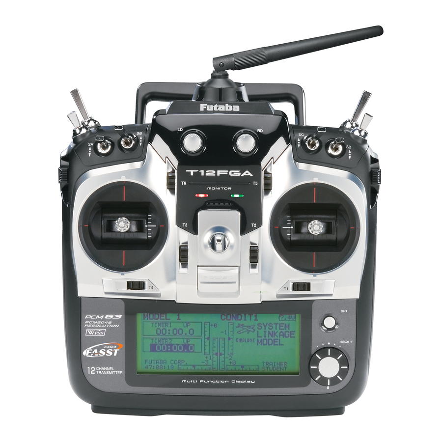
Transmitter controls (J3) (J2) (J4) (J1) Cautions on handling antenna WARNING Be sure to attach the antenna before operation. Never hold the antenna alone. *Antenna is stored in the antenna storage compartment in *Hold the carrying bar, otherwise the main body can be damaged. -
Page 13: Led Monitor
Monitor LED display •Removing and storing the antenna The status of the transmitter is displayed by LED To remove the antenna from the storage at the bottom left and right sides of the "T12FG" compartment, grasp the end of the antenna and pull logo. - Page 14 To change the trim rate, you must activate this Volume through the function menu, within the linkage menu. Use the EDIT dial to select the trim box and then push the EDIT button and you will access another screen which enables you to change the trim percentages.
-
Page 15: Edit Key
Edit keys operation Data input operation is performed using the EDIT dial/EDIT button, and S1 button. LCD screen: S1 button: When there is a next page on a menu screen or using the system menu screen setting [DISPLAY]. setup screen, you can go to that page by pushing the S1 button. -
Page 16: Stick Adjustment
Stick Adjustment Adjustment of Throttle Stick (Ratchet System) You can also choose either airplane ratchet Adjustment of the stick lever length system or helicopter-touch. sticks in line with your hand size. Lever Head Lever Head 1. Hold the lever head "B" and turn the lever head "A"... -
Page 17: Sd Card
[IMPORTANT] When an SD card is formatted, are identified by number instead of name. (The special all the existing data is destroyed. Do not conversion software can be downloaded from Futaba dealer format a card containing important data. web site.) [Formatting procedure] 1. -
Page 18: Connector/Plug
SD card reader/writer Connector for battery charger Saving model data and update files (released from Futaba) into the SD card, you can use those This is the connector for charging the Ni- files on your T12FG transmitter. Equipment for MH battery HT6F1700B that is installed in the reading and writing SD cards is available at most transmitter. - Page 19 Transmitter Battery transmitter. Do not use the transmitter as it is. Send it to the Futaba Service Center. Attachment of the battery 1. Open the battery cover on the rear of the transmitter toward upper side.
- Page 20 Receiver nomenclature Before using the receiver, be sure to read the precautions listed in the following pages. Receiver R5114DPS Connector "1 through 12": outputs for the channels 1 through 12 Connectors "DG1", "DG2": outputs of DG1 and DG2 channels "B/C": connector for the power and DSC. LED Monitor Antenna This monitor is used when changing the...
- Page 21 Safety precautions when you install receiver and servos Servo throw Warning Connecting connectors bind or sag when operating the servos to the full extent. Be sure to insert the connector until it stops at the deepest point. *If excessive force is continuously applied to a servo, your aircraft may crash because the servo would be damaged How to protect the receiver from vibration and and the battery would be consumed rapidly.
-
Page 22: Basic Operation
BASIC OPERATION Battery Charging Before charging batteries, read the "Cautions for handling battery and battery charger" in the section "Ni- MH/Ni-Cd Battery Safety and Handling Instructions". *Battery charging will not automatically stop. Remove the How to charge the Ni-MH battery HT6F1700B battery and transmitter from the charger and remove the for the transmitter and the Ni-Cd battery charger from the wall socket. -
Page 23: When Turning On
How to turn transmitter power ON/OFF How to change the frequency/How to set ID For safety reasons, the radio will be emmiting The T12FG system has employed the frequency only after confirming when turning on the power. synthesizer scheme. The T12FG transmitter will set Please follow the instructions for turning on/off the the frequency of the R5114DPS (PCMG3 receiver) transmitter. - Page 24 *The frequencies which can be selected appear on the screen. 2. Select the frequency you want to use and push the EDIT button. *When changing the frequency band, change the module before turning on the power. How to change the frequency 3.
-
Page 25: Home Screen
Home screen button. The setting screen appears. Airplane/Glider Home Screen Model Name Condition Name Battery Indicator • The model name that • The condition name • When the battery voltage is currently used is that is currently used reaches 6.8V, the alarm will displayed here. - Page 26 Helicopter Home Screen Throttle/Pitch Position Display • Throttle and pitch position is displayed here. Push the EDIT button to call the throttle curve or Pitch curve setting screen directly. *Condition hold operation is displayed. ("IS ON") To activate/deactivate Condition Hold: 1.Move the cursor to [CND HOLD].
-
Page 27: Functions Of System Menu
SYSTEM MENU The System Menu sets up functions of the transmitter: This does not set up any model data. S1 button EDIT dial E D I T EDIT EDIT button System Menu functions table [TRAINER]: Starts and sets the trainer system. [DISPLAY]: LCD contrast adjustment [SYSTEM TIMER]: Resets the accumulated timer for each model. -
Page 28: Trainer
(if MIX or the Instructor's transmitter. When the Instructor's FUNC mode is turned on, the Instructor can make transmitter is a T14MZ, 12Z, 12FG, T9Z, T9C or corrections while the student has control). When T7C transmitter, it should be switched to PPM mode. - Page 29 S1 button EDIT dial E D I T EDIT EDIT button When using at the student side When using at the teacher side *When changing the mode, use the EDIT dial to move to the *When changing the mode, use the EDIT dial to move to the item you want to change and push the EDIT button to switch item you want to change and push the EDIT button to switch to the data input mode and change the mode by turning the...
- Page 30 *Use the EDIT dial to move the cursor to the "MODE" item of the channel you want to change and push the EDIT button to switch to the data input mode and change the mode by turning the EDIT dial to the left or right. The display blinks. Press the EDIT button to change the mode.
- Page 31 DISPLAY LCD contrast adjustment is possible: S1 button EDIT dial E D I T EDIT EDIT button LCD contrast adjustment *Adjust to the contrast while watching the screen display. *When you want to reset the contrast to the initial state, select "LCD CONTRAST"...
-
Page 32: System Timer
SYSTEM TIMER This function resets the system timer displayed on the home screen. S1 button EDIT dial E D I T EDIT EDIT button Timer selection Timer reset <Functions of System Menu>... -
Page 33: User Name
USER NAME This function registers the T12FG user name. *A name of up to 12 characters can be entered as the user name. (Space is also counted as 1 character.) S1 button EDIT dial E D I T EDIT EDIT button User name registration *A name of up to 12 characters long can be entered as the user name. -
Page 34: H/W Setting
Those are mechanical changes that the indicators on the display. Use the Normal must be done by a Futaba service center. mode as long as there is no special reason to Note: After changing the mode, it is applied use the Reverse mode. -
Page 35: Information
INFORMATION The T12FG system program version information, The language displayed in home, menu, and SD card information (maximum and vacant number setup screen is selectable. of model data), and product ID are displayed on the Information screen. *When the SD card is not inserted, the SD card information is not displayed. -
Page 36: Model Basic Setting Procedure
MODEL BASIC SETTING PROCEDURE Airplane/glider basic setting procedure 3. Fuselage linkage 1. Model addition and call Connect the ailerons, elevators, throttle, rudder, Initial setting assigns 1 model to the T12FG etc. in accordance with the model's instruction transmitter. The Model Select function of the manual. - Page 37 5. Idle down setting The Condition Select function automatically allocates The idling speed can be lowered with one touch by is the default condition and is the only one active when a a switch without changing the throttle trim position. Perform this setting with the Idle Down function of the Linkage Menu.
- Page 38 Helicopter basic setting procedure This section outlines examples of use of the helicopter functions of the T12FG. Adjust the actual values, etc. to match the fuselage used. functions for the chosen model type. Eight swash types are 1. Model addition and call available for helicopters.
- Page 39 4. Fuselage linkage 5. Throttle/Pitch curve setting Connect the throttle rudder, aileron, elevator, This function adjusts the throttle or pitch pitch, and other servos in accordance with the operation curve in relation to the movement of the kit instruction manual. For a description of the throttle stick for each condition.
- Page 40 6. AFR (D/R) Model Menu, and set the curve for each condition. AFR (D/R) function is used to adjust the throw and operation curve of aileron, elevator and rudder for each condition. *For throttle and pitch curve settings, refer to the above- mentioned "Throttle/Pitch curve setting"...
- Page 41 pitch interaction The swash mix function is used to correct the swash plate in the aileron (Left/Right Cyclic) and elevator (Forward/Aft Cyclic) direction corresponding to each operation of each condition. *If throttle mixing is necessary for a compensation for slowing of engine speed caused by swash plate operation during aileron or elevator operation, please refer to the THROTTLE MIX function, p.113.
- Page 42 Receiver and servo connection Connect the receiver and servos in accordance with the connection diagram shown below. Always read [Precautions when mounting the receiver and servos] or [Before using]. When mounting the receiver and servos to the fuselage, connect the necessary points in accordance with the kit instruction manual. Receiver and servos connection diagram Ni-Cd battery Receiver switch...
- Page 43 Servo connection by model type The T12FG transmitter channels are automatically assigned for optimal combination according to the type selected with the Model Type function of the Linkage Menu. The channel assignment (initial setting) for each model type is shown below. Connect the receiver and servos to match the type used. *The set channels can be checked at the Function screen of the Linkage Menu.
- Page 44 [PCM-G3 mode] 1AIL 2AIL 2AIL+1FLAP 2AIL+2FLAP 2AIL+4FLAP 4AIL+2FLAP 4AIL+4FLAP Airplane Glider Airplane Glider Airplane Glider Airplane Glider Airplane Glider Airplane Glider Airplane Glider [PCM1024/PPM mode] 1AIL 2AIL 2AIL+1FLAP 2AIL+2FLAP Airplane Glider Airplane Glider Airplane Glider Airplane Glider <Model Basic Setting Procedure>...
- Page 45 [PCM-G3 mode] 2AIL 2AIL+1FLAP 2AIL+2FLAP 2AIL+4FLAP 4AIL+2FLAP 4AIL+4FLAP Airplane Glider Airplane Glider Airplane Glider Airplane Glider Airplane Glider Airplane Glider [PCM1024/PPM mode] 2AIL 2AIL+1FLAP 2AIL+2FLAP 2AIL+4FLAP 4AIL+2FLAP Glider Glider Glider Glider Airplane Glider Airplane Glider Airplane Glider Airplane Airplane Normal Winglet Normal Winglet...
- Page 46 Helicopter [PCM-G3 mode] RX CH H-4, H4X Swash All Other Throttle Throttle Rudder Rudder Aileron Gyro Elevator Aileron Pitch Elevator Elevator 2 Pitch Gyro Governor 1 Governor 1 Governor 2 Governor 2 Needle Needle AUX3 AUX2 AUX2 AUX1 AUX1 AUX1 AUX1 AUX1 AUX1...
-
Page 47: Functions Of Linkage Menu
FUNCTIONS OF LINKAGE MENU The Linkage Menu is made up of functions The functions which can be selected depend on which perform model addition, model type the model type. A typical menu screen is shown selection, frequency setting, end point setting, and below. -
Page 48: Servo Monitor
SERVO MONITOR This is used for testing servo movement. The “Neutral Test” is good for finding the “Moving Test” (repetition mode) and “Neutral neutral position of a servo horn. S1 button EDIT dial E D I T EDIT EDIT button *The display screen is an example. -
Page 49: Model Select
MODEL SELECT This function is used to load the settings of the always appears in the display screen. desired model into the T12FG’s memory. The Copy function is used to copy one set of model The settings may be selected from either the data into a second memory within the transmitter and transmitter’s built-in memory or a SD card (32MB- the SD card. - Page 50 Model deletion *The model stored in the transmitter memory or a SD card can be deleted. *The current model can not be deleted. Model copy *A copy can be made of the current model. *The copy screen appears. Model name change *The current model's name can be changed.
-
Page 51: Model Type
MODEL TYPE Seven types of main wings and three types of tail wings are available for airplanes. Eight swash types are available for helicopters. Seven types of main wings and three types of tail wings are available for gliders. Functions and mixing functions necessary for each model type are set in advance at the factory. - Page 52 Model type Select the model type f r o m a m o n g a i r p l a n e , helicopter, and glider. (Airplane, glider) (Helicopter) Helicopter swash type Select from among H-1, H-2, H-4, HR3, HN3, H-3, HE3, and H4X.
- Page 53 Model type selection (Airplane, Glider) Model type selection (Helicopter) <Functions of Linkage Menu>...
- Page 54 FREQUENCY Frequency setting PCM-G3 communication mode selection The T12FG transmitter uses a synthesizer Two types of PCM-G3 communication modes system. Its frequency can be changed within the can be selected. (Mode A and Mode B) range of the frequency band of the module used. Mode A is conventional mode and displays the The frequency of the R5114DPS receiver is set maximum performance of the servo response to...
- Page 55 *Once the ID code is set, re-setting is unnecessary as long as the receiver is not changed. PCM-G3 communication mode selection *The mode selection screen appears. *The communication mode is changed. WARNING waves only after verifying the frequency. *Also change the frequency clip. Emitting radio waves with- <Functions of Linkage Menu>...
-
Page 56: Function
FUNCTION When you select model and wing (swash) types, VC1~VC4 (virtual channels) you will find that the optimized combinations of These four channels can be set as virtual functions servo output channels and functions have been that do not have servo output channels. You can already preset. - Page 57 Trim setting *The trim setup screen is displayed. *The setting can be changed for each condition. After the set mode is changed from group mode [G] to single mode [S] at the control selection screen, only that condition setting is changed by control change; setting of other conditions remains the same.
- Page 58 SUB-TRIM The Sub-Trim function is used to set the servo neutral position, and may be used to make fine adjustments to the control surface after linkages and pushrods are hooked up. When you begin to set up a model, be sure that the digital trims are set to their center position.
- Page 59 SERVO-REVERSE Servo Reverse changes the direction of an that control multiple servos, it may be confusing individual servo’s response to a control stick to tell whether the servo needs to be reversed or a movement. setting in the function needs to be reversed. See the instructions for each specialized function for further For CCPM helicopters, be sure to read the details.
-
Page 60: Fail Safe
FAIL SAFE The Failsafe function may be used to set up positions control suddenly moves to a position you did not that the servos move to in the case of radio interference. command, land at once and check your receiver battery. -
Page 61: End Point
END POINT The End Point function adjusts the left and right NOTE: The Servo Speed setting is used to set the servo delay for each channel, from channel l to channel 12. The system servo throws, generates differential throws, and uses the programmed speed (delay) to slow down servo will correct improper linkage settings. -
Page 62: Throttle Cut
THROTTLE CUT Throttle cut provides an easy way to stop the at idle. The action is not functional at high throttle to avoid accidental dead sticks. The switch’s location and direction must be chosen, as it defaults to NULL. S1 button EDIT dial E D I T EDIT... - Page 63 IDLE DOWN The Idle Down function lowers the engines idle The action is not functional at high throttle to avoid accidental dead sticks. The switch’s location and direction must be chosen, as it defaults to NULL. S1 button EDIT dial E D I T EDIT EDIT button...
- Page 64 SWASH RING This function limits the swash travel to within a fixed range to prevent damaging of the swash linkage by simultaneous operation of the ailerons and elevators. It is effective in 3D aerobatics which use a large travel. S1 button EDIT dial E D I T EDIT...
- Page 65 SWASH The following compensation mixing is possible; Neutral Point PIT to AIL, PIT to ELE, AIL to PIT, ELE to AIL, At your linkages, if the servo horn deviates from and ELE to PIT (HR3 mode.) It adjusts the swash- a perpendicular position at neutral, the linkage plate to operate correctly for each control using the compensation functions in this menu may not...
- Page 66 Mixing rate setting procedure The HR-3 is taken as an example to describe mixing rate setting. Mixing applied in other swash modes is different, but the setting procedure is the same. *When making the following setting, use the EDIT dial to move the cursor to the item you want to set and push the EDIT button to switch to the data input mode.
-
Page 67: Timer
TIMER Each timer may be set for count-down or count The Timer function may be set for any desired time, up operation with a target time. If a target time is set and the timer reaches the set etc. Two independent timers are provided for your use. time, a buzzer sound for each count is generated. - Page 68 T1-T6 SETTING This function adjusts the digital trim's control step amount and operation mode (T1~T6.) When the flight conditions are set, the trim operation can be coupled with among all the conditions which combination mode is selected. S1 button EDIT dial E D I T EDIT EDIT button...
-
Page 69: Data Reset
DATA RESET This function is designed to allow you to reset Model menu setting: selected portions or all of the settings saved in Resets all the functions in the Model Menu the active model memory. You may individually except Condition Select. choose to reset the following sets of data;... - Page 70 COND.HOLD To activate/deactivate Condition hold: speed of the engine so that you may adjust flight (Home screen) conditions when the engine is running. An alarm indicates that the function is operating. It will prevent the engine from racing dangerously when adjusting the Idle-Up settings.
-
Page 71: Functions Of Model Menu
MODEL MENU (COMMON FUNCTIONS) This section describes the AFR, program mixing, Select function to add flight conditions. (Up to 8 and other functions common to all model types. conditions can be used) Before setting the model data, use the Model Type function of the Linkage Menu to select the model type matched to the fuselage. -
Page 72: Condition Select
The functions in the Model Menu can be used by switching the settings of up to 8 flight conditions conditions. Add conditions, as required. When you do not want to use the Condition Select function, this setting is unnecessary. In this case, use the flight conditions assigned at initial setting. - Page 73 Condition name change *The models already saved are displayed at the right side of the screen. *The number before the condition name become reverse- video to show that it is to be deleted. *The copy destination conditions are displayed at the "DESTIN.COND."...
-
Page 74: Afr
AFR function is used to adjust the throw and operation curve of the stick, lever, and switch functions (CH1 to CH12, and V1 to V4) for each flight condition. This is normally used after End Point has defined the maximum throw. When mixing is applied from one channel to another channel, both channels can be adjusted at the same time by adjusting the operation rate through the... -
Page 75: Dual Rate
D/R curves which can be switched by switch, etc. can be added. The curve can be adjusted by the AFR function. S1 button EDIT dial E D I T EDIT EDIT button (For a detailed description of the setting method, see [Switch Setting Method] at the end of this manual.) <Model Menu (Common Functions)>... - Page 76 have mixing remaining on all the time. Mixing ON/OFF Programmable mixing may be used to correct undesired tendencies of the aircraft, and it may also be delay time can be adjusted. The Programmable mixing includes a powerful link that the motion of a command channel, called the function, which allows Programmable mixing to be "master,"...
- Page 77 (For a description of the setting method, see the description at the back of this manual.) (For a description of the setting method, see the description at the back of this manual.) (For a description of the switch setting method, see the description at the back of this manual.) *Perform the settings below after using the EDIT dial to (For a description of the setting method, see [Switch Setting...
- Page 78 (When the EDIT button is pushed for 1 second, the delay time is reset to the initial value.) *Check the direction by actual operation. *When mixing includes master side trim, select [ON] and when mixing does not include master trim, select [OFF]. *Effective when a function is set at the master channel.
-
Page 79: Model Menu Functions List
MODEL MENU (AIRPLANE/GLIDER FUNCTIONS) The dedicated mixes, etc. usable when airplane condition by switch or stick position, use the or glider model type is selected are displayed in this Model Menu functions section. First use the (Up to 8 conditions can be used) Model Type function of the Linkage Menu to preset the model type, wing type, and tail type matched to the fuselage used. - Page 80 RUD to AIL GYRO This mix is used to correct roll maneuvers, knife edge, etc. of stunt planes. [Airplane/glider, V-TAIL general] CAMBER Mix AILEVATOR ELE to CAMBER WINGLET CAMBERFLP to ELE MOTOR BUTTERFLY (Crow) RUD to ELE TRIM MIX 1/2 SNAP ROLL AIRBRAKE AIR BRAKE...
-
Page 81: Ail Differential
AIL DIFF. The left and right aileron differential can be adjusted independently. The differential rate can also be adjusted according to the flying state by AIL1 AIL 2 (Main Aileron) (Main Aileron) AIL 3 AIL 4 (Chip Aileron) (Chip Aileron) (Currently selected condition name) (For more information, refer to the description at the back of this manual.) -
Page 82: Flap Setting
FLAP SETTING independently at each servo according to the wing type. The camber flaps of a 4-flap model can be FLP 4 FLP 3 (Brake Flap) (Brake Flap) FLP 1 FLP 2 FLP) (Camber Flap) (Camber Flap) *The display screen is an example. The actual screen depends on the model type. -
Page 83: Ail To Camber Flp
AIL to CAMB.FLP This mix operates the camber flaps (FLP1/2) in the aileron mode. When the aileron stick is manipulated, the ailerons and camber flaps perform aileron operation simultaneously and the operation characteristic of the roll axis is improved. FLP 1 FLP 2 (Camber Flap) (Camber Flap) -
Page 84: Ail To Brakeflp
AIL to BRAKEFLP in the aileron mode. When the aileron stick is manipulated, the aileron and brake flaps perform the aileron operation simultaneously and the operation characteristic of the roll axis is improved. FLP 4 FLP 3 (Brake Flap) (Brake Flap) AIL1 AIL 2 (Main Aileron) -
Page 85: Ail To Rud
AIL to RUD Use this mix when you want to mix the rudders with aileron operation. AIL1 AIL 2 (Main Aileron) (Main Aileron) AIL 3 AIL 3 (Chip Aileron) (Chip Aileron) RUDDER 1 RUDDER 2 Winglet Winglet at Flying wing at Flying wing V-TAIL RUDDER 2... -
Page 86: Airbrake To Ele
AIRBRAKE to ELE This mix is used when you want to mix the elevators with airbrake (spoiler) operation. It raises the elevators to correct for dropping of the AIRBRAKE nose during airbrake operation. *This function does not operate when airbrake is not assigned at the Function menu in the Linkage Menu. - Page 87 Setting method [Fine tuning VR operation mode] [LIN.] [ATL+] [ATL-] [SYM.] <Model Menu (Airplane/Glider Functions)>...
-
Page 88: Rud To Ail
RUD to AIL This function is used when you want to mix the ailerons with rudder operation. It is used when rudder is applied during roll maneuvers, knife edge, etc. of stunt planes. It can be used to bank scale models, large models, etc. like a full AIL1 AIL 2 (Main Aileron) -
Page 89: Camber Mix
CAMBER MIX This function adjusts the AFR (D/R) rate of camber operation which operates the wing camber (ailerons, camber flaps, brake flaps) in the negative and positive directions. The aileron, flap, and elevator rates can also be adjusted independently by curve, and attitude changes caused by camber operation can be corrected. - Page 90 Setting method FLP 4 FLP 3 (Brake Flap) (Brake Flap) FLP 1 FLP 2 (Camber Flap) (Camber Flap) AIL1 AIL 2 (Main Aileron) (Main Aileron) AIL 3 AIL 4 (Chip Aileron) (Chip Aileron) AILVATOR V-TAIL ELEVATOR ELEVATOR ELEVATOR 2 ELEVATOR 2 <Model Menu (Airplane/Glider Functions)>...
-
Page 91: Ele To Camber
ELE to CAMBER This function is used when you want to mix the when this mix is activated. be increased. Note: Tailless wing elevator can be operated (Currently selected condition name) S1 button EDIT dial E D I T EDIT EDIT button *For a description of the curve setting method,... -
Page 92: Camber Flp To Ele
CAMB.FLP to ELE This mixing is used to correct changes (elevator FLP 1 FLP 2 (Camber Flap) (Camber Flap) AILVATOR V-TAIL ELEVATOR ELEVATOR ELEVATOR 2 ELEVATOR 2 (Currently selected condition name) S1 button EDIT dial E D I T EDIT EDIT button *For a description of the curve setting method, see the description at the back of this manual. - Page 93 BUTTERFLY This function allows powerful brake operation by simultaneously raising the left and right ailerons and lowering the flaps (camber flap, This setting will allow the ailerons to be raised while the flaps are simultaneously lowered. landing configuration by accomplishing the *When servo binding occurs when setting the ailerons and rudder angle.
- Page 94 *For a description of the curve setting method, see the description at the back of this manual. (For a description of the setting method, see the description at the back of this manual.) FLP 4 FLP 3 (Brake Flap) (Brake Flap) FLP 1 FLP 2 (Camber Flap)
- Page 95 TRIM MIX 1/2 These functions call the ailerons, elevators, and Example The amount of ailerons, elevator, and flaps *When separating the settings for each condition, move to the [GROUP] item and set it to [Single]. a switch. As an example Trim Mix 1 can be set up for and a slight amount of up elevator.
- Page 96 (For more information, see the description at the back of this manual.) (For a description of the setting method, see the description at the back of this manual.) FLP 4 FLP 3 (Brake Flap) (Brake Flap) FLP 1 FLP 2 (Camber Flap) (Camber Flap) AIL1...
- Page 97 AIRBRAKE This function is used when an air brake is necessary when landing or diving, etc. The preset elevators and flaps (camber flap, brake flap) offset amount can be activated by a switch. match the aircraft. The offset amount of the aileron, elevator, and flap servos can be adjusted as needed.
- Page 98 (For more information, see the description at the back of this manual.) (For a description of the setting method, see the description at the back of this manual.) FLP 4 FLP 3 (Brake Flap) (Brake Flap) FLP 1 FLP 2 (Camber Flap) (Camber Flap) AIL1...
- Page 99 GYRO *Initial setting does not assign a sensitivity channel. Use the Function menu of the Linkage Menu to assign the sensitivity is used to stabilize the aircraft's attitude. The beforehand. mode) can be switched with a switch. Set [Control] and [Trim] other than Function to [--]. (Currently selected condition name) S1 button EDIT dial...
- Page 100 V-TAIL V-TAIL This function let’s you adjust for left and right rudder angle changes at elevator and rudder control rudder movement as elevators. In addition ELEVATOR to each rudder side moving up and down together, (RUDDER 2) each side moves in opposite directions when moving RUDDER (ELEVATOR 2) Ruddervator, as they can serve the same purpose.
- Page 101 AILEVATOR (Effective only when 2 servos used at the elevators) This function improves the operating performance of the roll axis by operating the elevators as ailerons. Ailevator is where each elevator in a standard (conventional) or v-tail moves independently, like ailerons on a wing.
-
Page 102: Winglet
WINGLET This function adjusts the left and right rudder angles of airplanes with winglets. Winglets are used to improve the efficiency of aircraft lowering the lift-induced drag caused by wingtip vortices. The winglet is a vertical or angled extension at the tips of each wing. RUDDER 1 Winglet Winglets work by increasing the effective aspect... -
Page 103: Motor
MOTOR This function lets you set the operation speed when the motor of a F5B or other EP glider is started by switch. The operation speed can be set in 2 ranges of slow speed flight and high speed operated as a safety function by setting 2 switches. Note: When using this function, always check initial operation with the propeller removed. -
Page 104: Rud To Ele
RUD to ELE This function is used when you want to mix elevator operation with rudder operation. It is used to correct undesirable tendencies when rudder is applied in roll maneuvers, knife edge, etc. of stunt planes. (Currently selected condition name) S1 button EDIT dial E D I T... -
Page 105: Snap Roll
SNAP ROLL This function selects the switch and rate (Example) Setting example for F3A adjustment of each rudder, (ailerons, elevators, or *The snap roll up side left and right and down side left and right direction switches are selected here. (Currently selected condition name) S1 button EDIT dial... -
Page 106: Model Menu Functions List
MODEL MENU (HELICOPTER) This section contains information on the data at each function. (Up to 8 conditions can be commands that apply to helicopters only. For used) instructions on Airplanes and Sailplanes, refer to The AFR function, Dual rate function and other the sections pertaining to those aircraft. -
Page 107: Pit Curve
PIT CURVE/PIT TRIM PIT Curve This function adjusts the pitch operation curve the number of input points to 3 or 5, and then entering the a curve. relative to movement of the throttle stick. *Up to 17 points can be set for the point curve types. create a curve, a simple curve can be created by reducing (Currently selected condition name) S1 button... - Page 108 Setting method Curve setting examples *For a description of the curve setting method, see the The screens shown below are curves created description at the back of this manual. by entering the pitch rate at low, center, and high side (3 points or 5 points) at each condition. When the fuselage (or the reference value).
- Page 109 Hovering pitch trim High Pitch/Low Pitch Trim The Hovering Pitch trim function trims the pitch High Pitch/Low Pitch Trim is the pitch servo near the hovering point. Normally, it is used with high side and low side trim function. the hovering condition. The hovering pitch can be Setting method conditions.
- Page 110 THR CURVE/THROTTLE HOVER TRIM THR Curve This function adjusts the throttle operation curve point data is used, a simple curve can be easily for each condition for optimum engine speed to created by reducing the number of input points of throttle stick movement.
- Page 111 Curve setting examples to 5. When actually creating a curve, enter the data The curves shown below are created by using the point curve type and inputting the data of the 5 points 0% (low side), 25%, 50% (center), 75%, *For a description of the curve creation method, see the 100% (high) side at each condition.
-
Page 112: Acceleration
ACCELERATION This function is used to adjust the pitch and Example of acceleration function use the throttle rise characteristic at acceleration/ deceleration operation. An acceleration function which temporarily increases the pitch and throttle operations at throttle stick acceleration/deceleration operation can be set. (Currently selected condition name) S1 button EDIT dial... -
Page 113: Throttle Hold
THR HOLD This function sets the throttle cut position for Example of use auto rotation. The throttle position can also be set to an idling position. Setting of these 2 positions can be selected by switch. This allows use for switching during training. -
Page 114: Swash Mix
SWASH MIX The swash mix function is used to correct the Example of use swash plate in the aileron (roll) direction and elevator (cyclic pitch) corresponding to each operation of each condition. Adjustment by independent curve for aileron, elevator, and pitch operations is possible. The operation can be smoothly adjusted by calling up the “Curve setup”... -
Page 115: Throttle Mix
THROTTLE MIX This function corrects slowing of engine speed to the mixing item corresponding to the mixing caused by swash plate operation during aileron that needs correction and push the EDIT button to or elevator operation. The method of applying call the curve setup screen, and then correct the clockwise or counterclockwise torque when slowing. -
Page 116: Pit To Needle
PIT to NEEDLE mixing This mixing is used when the engine is equipped acceleration/deceleration operation can be set. with needle control or other fuel-air mixture The rise characteristic of the needle servo at adjustment. A needle curve can be set. acceleration and deceleration operation can be adjusted. - Page 117 PIT to RUD mixing (Revolution mixing) Use this mix when you want to suppress the However, when a GY Series or other heading reaction torque generated by main rotor pitch and hold gyro is used, since correction is performed speed changes during pitch operation. Adjust so by the gyro, this mix is not used.
- Page 118 GYRO mixing This function used to adjust gyro sensitivity. The Setting example sensitivity and operation mode (Normal mode/GY mode) can be set for each condition. *Sensitivity setting is assigned to CH3. (Rate No. display) (Currently selected condition name) S1 button EDIT dial E D I T EDIT...
- Page 119 GOVERNOR mixing When using a Futaba GV-1 governor, this *When using the Fuel Mixture function, the mixture servo is controlled from the governor. When transmitting the function is used to switch the RPM of the mixture curve data from the transmitter to the governor, the helicopters head.
-
Page 120: Screen
Common operations used in function setup screen This section describes the functions often used at the function setup screen. Refer to it when setting each function. Group/single mode switching (GROUP/SINGLE) Condition delay setting When setting multiple flight conditions, Unnecessary fuselage motion generated when linking the setting contents with all conditions there are sudden changes in the servo position (group mode) or setting independently (single... - Page 121 (Fine tuning VR operation position) *The operation modes which can be selected depend on the function. [Setting method] [Fine tuning VR operation mode] 1. Control selection [LIN.] Use the EDIT dial to move the cursor counterclockwise, the mixing rate (reverse-video) to the [CTRL] item and push increases and decreases, respectively.
- Page 122 Operations related to servo speed Servo speed setting The servo speed at each function operation (including flight condition switching) can be adjusted. The servos operate smoothly at a fixed speed corresponding to the set speed. The operating speed (IN side) and return speed (OUT side) can be set individually.
- Page 123 Curve setting operation This section describes the setting procedure of curves which are used with the AFR function and each mixing function. Curve type selection Three types of curves (EXP1, EXP2 and Curve type selection POINT) can be selected. 1. Use the EDIT dial to move the cursor (reverse-video) to the [MODE] item and push the EDIT button to switch to the data input mode.
- Page 124 2. When the EDIT button is pushed for 1 Point curve (POINT) adjustment second, the point is deleted. (Point) [Offsetting the curve horizontally in the vertical direction] 1. Use the EDIT dial to move the cursor (reverse-video) to the [OFFSET] item. 2.
- Page 125 Switch selection method The various functions used in the T12FG can be selected by switch. The switch (including when stick, trim lever, or VR are used as a switch) setting method is common to all functions. Switch selection When a switch is selected at a mixing function, etc., the selection screen shown below is called. (Switch selection screen example) Switch selection When stick, trim lever, or knob selected...
- Page 126 Operation modes Shifting the ON/Off point The operation modes when stick, trim lever, or The ON/OFF point can be shifted. ON/OFF at knob was selected are described below. a free position can be changed. Linear mode [Setting method] 1. First, use the EDIT dial to move the cursor This mode sets ON/OFF at the left or right (up or to the [POSITION] item.
- Page 127 (Logic switch setting screen) Swich selection 1. Select the switch A and B. (Refer to the description at the previous page.) FUTABA CORPORATION Phone: (043) 296-5118 Facsimile: (043) 296-5124 Makuhari Techno Garden Bldg., B6F 1-3 Nakase, Mihama-ku, Chiba 261-8555, Japan ©FUTABA CORPORATION 2007, 04 (1) <Data>...