
Related Manuals for FUTABA 12Z Series


Summary of Contents for FUTABA 12Z Series
-
Page 1: Instruction Manual
12 CHANNEL RADIO CONTROL SYSTEM PCMG3/PCM1024/FM selectable INSTRUCTION MANUAL 1M23N16902... -
Page 2: Table Of Contents
TABLE OF CONTENTS INTRODUCTION..........4 ..... 24 ............ 25 ......... 4 ... 5 FUNCTIONS OF SYSTEM MENU....27 ........6 ............. 28 ............. 30 ............. 6 ............... 31 ..........32 BEFORE USE ............. 9 ............33 ..........9 ........... 35 ... - Page 3 FUNCTIONS OF MODEL MENU ........106 ......106 ........69 ........107 ....110 ..........70 ..........112 ............72 ..........113 ........... 74 ............. 114 ........... 77 ..........115 ... 78 ..........116 ......78 ..... 117 ..........80 .............
-
Page 4: Introduction
INTRODUCTION Thank you for purchasing the Futaba® 12Z series digital proportional R/C system. In order for you to make the best use of your system and to fly safely, please read this manual carefully. If you have any difficulties while using your system, please consult the manual, our online Frequently Asked Questions (on the web pages referenced below), your hobby deal- er, or the Futaba Service Center. - Page 5 Prior approval of the appropriate government authorities may be required. If you have purchased this product from an exporter outside your own country and not the authorized Futaba dis- tributor in your country, please contact the seller immediately to determine if such export regulations have been met.
- Page 6 Have regular maintenance performed. Although your 12Z protects the model memories with non-volatile EEPROM memory (which does not require periodic replacement) and not a battery, it still should have regular checkups. We recommend sending your system to the Futaba Service Center annually during your non-flying season for a complete checkup and service.
- Page 7 Lithium-Polymer (LiPo) batteries, or any other type of rechargeable battery (including NiCd’s and NiMH’s). Li-Ion batteries require special charging criteria different than other rechargeable batteries. Use only the Futaba lithium ion transmitter charger included with this set for, or other chargers approved by Futaba to charge the Li-Ion batteries in the 1 Z transmitter.
- Page 8 AT THE FLYING FIELD Always pay particular attention to the flying fields’ rules, as well as the presence and location of spectators, the wind direction, and any obstacles on the field. Be very careful flying in areas near power lines, tall buildings, or communication facilities as there may be radio interference in their vicinity.
-
Page 9: Before Use
T12Z is operated by 7.4V/2,200 mAh Lithium-Ion battery. R5014DPS The R5014DPS is a small 14CH synthesized receiver with high sensitivity and selectability. CF (Compact Flash) card (Optional) Model data can be saved in an optional Futaba CF card (CFDP32M, etc.) When T12Z transmitter <Before Use>... - Page 10 Your 12ZA/12ZH/12Z (packaged with a 14-channel PCM-G3 receiver) includes the following components: Suggested Servos for use with your 12Z • T12Z Transmitter, including RF module (MZ-DDS) Servo S9154 (Digital servo) • R5014 Receiver Control system: Pulse width control, 1.52 ms neutral •...
-
Page 11: Accessories
Battery/DSC (B/C) slot. All programming and setup may be done in this manner without transmitting. • Receivers - various models of Futaba receivers may be purchased for use in other models. (Receivers for PCM-G3, PCM1024, or FM/PPM types are available.) •... -
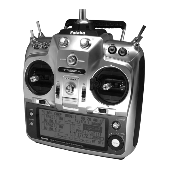
Page 12: Transmitter Controls
Transmitter controls (J3) (J2) (J4) (J1) Cautions on handling antenna WARNING Be sure to attach the antenna before operation. Never hold the antenna alone. *Antenna is stored in the antenna storage box in the trans- *Hold the carrying bar, otherwise the main body can be damaged. - Page 13 Mount the antenna by turning it clockwise until turns to pink color. it locks in place. • The 12Z logo turns blue when you use the DSC cable, or when the trainer function is set at student's side. • The 12Z logo blinks red slowly when you attach the RF module that is different from the setting.
- Page 14 Volume Digital trim This transmitter is equipped with digital trims. Each time you press a trim button, the trim position moves one step. If you continue pressing it, the trim position starts to move faster. In addition, when the trim position returns to the center, the tone will change.
- Page 15 Edit Key Data input operation is performed using the cursor lever, data input dial/enter button, and return key. CURSOR HOME DATA RETURN PUSH DIGITAL PROPORTIONAL RADIO CONTROL SYSTEM LCD screen: among setting items on setup screens. Up, down, left, and right movements are possible. Push the cursor lever when you want to go system menu screen setting [DISPLAY].
- Page 16 Adjustment of the stick lever length Adjustment of Throttle Stick (Ratchet System) You can also choose either airplane ratchet system or helicopter-touch. sticks in line with your hand size. Lever Head Lever Head 1. Hold the lever head "B" and turn the lever head "A"...
- Page 17 CF card memory size is 32MB. Read data from a PC Saving model data and update files (released from Futaba) into the CF card, you can use those files on your T12Z transmitter. Equipment for reading and writing CF cards are available at most electronics stores.
- Page 18 Connector/Plug CR-2500 that is for 12V application to charge the LT2F2200 battery through this connector. Danger Do not connect any other chargers except CR-2500 to this charging connector. *If you take out the Lithium Ion battery LT2F2200 from the transmitter, you can use the attached charger LBC-1D5 for charging the battery.
- Page 19 * If there is any problem, the message "Backup Error" will be shown the next time when you turn on the power of the transmitter. Do not use the transmitter as it is, send it to the Futaba Service Center. RF module MZ-FM Caution Be sure to turn off the power of the transmitter before you attach or detach the module.
- Page 20 Receiver nomenclature Before using the receiver, be sure to read the precautions listed in the following pages. Receiver R5014DPS Connector "1 through 12": outputs for the channels 1 through 12 Connectors "DG1", "DG2": outputs of DG1 and DG2 channels Antenna "B/C": connector for the power and DSC.
- Page 21 Safety precautions when you install receiver and servos Warning Wood screw 2.3-2.6mm nut Connecting connectors washer Rubber Rubber grommet grommet Brass eyelet Be sure to insert the connector until it stops at Brass eyelet Servo mount the deepest point. Servo mount 2.3-2.6mm screw (Airplane/Glider) (Helicopter)
-
Page 22: Basic Operation
BASIC OPERATION Battery Charging Before charging batteries, read the "Cautions for handling battery and battery charger" in the section "Lithium-Ion Battery Safety and Handling Instructions". How to charge the Lithium Ion battery How to charge the Ni-Cd battery NR4F1500 for LT2F2200 for the transmitter the receiver Use the battery charger FBC-32A that is included... - Page 23 How to turn ON/OFF the power of the How to change the frequency/How to set ID transmitter The T12Z system has employed the frequency synthesizer scheme. The T12Z transmitter will set For safety reasons, the radio will be emmiting the frequency of the R5014DPS (PCMG3 receiver) only after confirming when turning on the power.
- Page 24 is displayed and the frequency data is sent to the receiver 5. If the frequency is correct, push the enter together with a message sound. (The frequency data can be button. resent by selecting [RETRY] and pushing the enter button.) 6.A confirmation message ("TRANSMIT?") is 8.
- Page 25 Home screen Use the cursor lever to select the following display area to call each setting screen, and push the enter button. The setting screen appears. Airplane/Glider/EP Glider Home Screen System timer Model Name • This shows the accumulated time since the latest reset.
- Page 26 Helicopter Home Screen *Condition hold operation is displayed. ("IS ACTIVE") To activate/deactivate Condition Hold: 1.Move the cursor to [CND HOLD]. 2.Set the throttle stick lower than the 1/3 point and push the enter button to activate/deactivate the condition hold function. *See p.68 for condition hold function details.
-
Page 27: Functions Of System Menu
SYSTEM MENU The System Menu sets up functions of the transmitter, this does not set up any model data. [Cursor Lever] [Return Key] [Data Input Dial] PUSH [Enter Button] System Menu functions table [TRAINER]: Starts and sets the trainer system. [DISPLAY]: Display adjustment and auto power off setting. - Page 28 (if MIX or by the Instructors’ transmitter. When the FUNC mode is turned on, the Instructor can make Instructors’ transmitter is a T14MZ, 12Z, T9Z, T9C or T7C transmitter, it should be switched corrections while the student has control). When to PPM mode.
- Page 29 *The setting above allows setting of the servo throw relative to the amount of student side operation when [MIX] or [FUNC] was selected. *When setting the switch at each channel, use the cursor lever to move to the "SW" item of the channel you want to change, call the switch setup screen by pushing the enter button, and select the switch.
- Page 30 DISPLAY The following LCD screen adjustments and auto power off setting are possible: [Cursor Lever] [Return Key] [Data Input Dial] PUSH [Enter Button] LCD contrast adjustment Auto power off time setting *Use the cursor lever to select "LCD CONTRAST" and adjust the contrast by turning the data input dial to the left *When the amount of time a stick, switch, etc.
- Page 31 SOUND This function adjusts the volume of the edit operation, trim and knob operation, and power ON/ from the transmitter speaker. [Cursor Lever] [Return Key] [Data Input Dial] PUSH [Enter Button] Volume adjustment *Adjust the speaker volume by turning the data input dial to the left and right.
- Page 32 SYTEM TIMER This function resets the system timer displayed on the home screen and other setup screens. [Cursor Lever] [Return Key] [Data Input Dial] PUSH [Enter Button] Timer reset <Functions of System Menu>...
- Page 33 This function registers the T12Z user name. forget the PIN, none of the settings can be changed. In this A PIN can also be set to protect the set data or case, the system must be reset by the Futaba Service Center. user name. [Cursor Lever]...
- Page 34 digit, use the cursor lever to select the arrow symbol and move the arrow symbol by pushing the enter button. *Once the transmitter power is turned off, the set security mode is enabled. *When a PIN number was set for the user name, the PIN number must be input the next time the user name setup screen is opened.
- Page 35 H/W REVERSE Note: This setting reverses the actual operation This function reverses the operation signal of the signal, but does not change the display of sticks, switches, trimmer levers, and knobs. the indicators on the display. Use the Normal mode as long as there is no special reason to use the Reverse mode.
- Page 36 INFORMATION The T12Z system program version information, CF card information (memory size, vacant capacity, number of model data), and product ID are displayed on the Information screen. *When the CF card is not inserted, the CF card information is not displayed. [Cursor Lever] [Return Key] [Data Input Dial]...
-
Page 37: Model Basic Setting Procedure
MODEL BASIC SETTING PROCEDURE Airplane/glider basic setting procedure 1. Model addition and call Initial setting assigns 1 model to the T12Z transmitter. The Model Select function of the Linkage Menu is used to add models and to select models which are already set. 3. - Page 38 4. Throttle cut setting servos can be adjusted as needed. Also the speed of the Throttle cut can be performed with one touch by a side/OUT side) A delay can be set for each condition, switch without changing the throttle trim position. and a Cut switch which will turn OFF the delay can be Set throttle cut with the Throttle Cut function of chosen.
- Page 39 Helicopter basic setting procedure etc. to match the fuselage used. 1. Model addition and call Default setting assigns 1 model to the T12Z. To add new models or to call a model already set, use the Model Select function of the Linkage Menu. 3.
- Page 40 4. Fuselage linkage Connect the throttle rudder, aileron, elevator, pitch, and other servos in accordance with the kit instruction manual. For a description of the connection method, see "Receiver and Servos Connection". *The channel assignment of the T12Z is different assigned to each function can be checked at the Function menu of the Linkage Menu.) 5.
- Page 41 Use this function when you want to suppress the torque generated by the changes in the pitch and speed of the main rotor during pitch operation. Adjust it so that the nose does not swing in the rudder direction. However, when using a heading <...
- Page 42 11. Throttle cut setting º Throttle cut provides an easy way to stop the *For this curve, [Linear] curve type can be used and the entire curve can be lowered with the [Offset] function. at idle. The action is not functional at high throttle to avoid accidental dead sticks.
- Page 43 Receiver and servo connection Connect the receiver and servos in accordance with the connection diagram shown below. Always read [Precautions when mounting the receiver and servos] of [Before using]. When mounting the receiver and servos to the fuselage, connect the necessary points in accordance with the kit instruction manual. Receiver and servos connection diagram Ni-Cd battery Receiver switch...
- Page 44 Servo connection by model type The T12Z transmitter channels are automatically assigned for optimal combination according to the type selected with the Model Type function of the Linkage Menu. The channel assignment (initial setting) for each model type is shown below. Connect the receiver and servos to match the type used. *The set channels can be checked at the Function screen of the Linkage Menu.
- Page 45 1AIL 2AIL 2AIL+1FLAP 2AIL+2FLAP RX CH Glider Glider Glider Glider Airplane Airplane Airplane Airplane Elevator Elevator Elevator Elevator Elevator Elevator Elevator Elevator Elevator Elevator Elevator Elevator Elevator2 Elevator2 Elevator2 Elevator2 Elevator2 Elevator2 Elevator2 Elevator2 Elevator2 Elevator2 Elevator2 Elevator2 Rudder Rudder Rudder Rudder Rudder Rudder Rudder Rudder Rudder Rudder Rudder Rudder Aileron Aileron Aileron Aileron Aileron Aileron Aileron Aileron Aileron Aileron Aileron Aileron Throttle Motor...
- Page 46 2AIL 2AIL+1FLAP 2AIL+2FLAP RX CH Glider Glider Glider Airplane Airplane Airplane Rudder Rudder Rudder Rudder Rudder Rudder Rudder Rudder Rudder Rudder2 Rudder2 Rudder2 Rudder2 Rudder2 Rudder2 Rudder2 Rudder2 Rudder2 Throttle Motor AUX1 Throttle Motor AUX7 Throttle Motor AUX6 Aileron Aileron Aileron Aileron Aileron Aileron Aileron Aileron Aileron Aileron2 Aileron2 Aileron2 Aileron2 Aileron2 Aileron2 Aileron2 Aileron2 Aileron2 Gear AUX7...
- Page 47 Helicopter H-4 Swash All Other Throttle Throttle Rudder Rudder Aileron Gyro Elevator 1 Aileron Pitch Elevator Elevator 2 Pitch Gyro Governor 1 Governor 1 Governor 2 Governor 2 Needle Needle AUX3 AUX2 AUX2 AUX1 AUX1 AUX1 AUX1 AUX1 AUX1 AUX1 AUX1 AUX1 AUX1...
-
Page 48: Functions Of Linkage Menu
FUNCTIONS OF LINKAGE MENU The Linkage Menu is made up of functions The functions which can be selected depend on which perform model addition, model type the model type. A typical menu screen is shown selection, frequency setting, end point setting, and below. -
Page 49: Servo Monitor
SERVO MONITOR This is used for testing servo movement. “Moving Test” (repetition mode) and “Neutral position of a servo horn. [Cursor Lever] [Return Key] [Data Input Dial] PUSH [Enter Button] *The display screen is an example. The screen depends on the model type. Servo test operation <Functions of Linkage Menu>... -
Page 50: Model Select
MODEL SELECT This function is used to load the settings of the always appears in the display screen. desired model into the T12Z’s memory. The Copy function is used to copy one set of model The settings may be selected from either the data into a second memory within the transmitter and transmitter’s built-in memory or a CFDP32M (Compact the CF card. -
Page 51: Model Copy
Model deletion Model copy *The model stored in the transmitter memory or a CF card *A copy can be made of the model saved in the transmitter can be deleted. memory or a CF card. *The copy screen appears. Model name change *The model name saved in the transmitter memory or a CF card can be changed. -
Page 52: Model Type
MODEL TYPE Seven types of main wings and three types of tail wings are available for airplanes. Seven swash types are available for helicopters. Seven types of main wings and three types of tail wings are available for gliders. Functions and mixing functions necessary for each model type are set in advance at the factory. - Page 53 Model type Select the model type f r o m a m o n g a i r p l a n e , helicopter, glider, and motor glider. (Airplane, glider) (Helicopter) Helicopter swash type Select from among H-1, H-2, H-4, HE3,HN3, and H-3.
- Page 54 FREQUENCY Frequency setting of the receiver case must be entered. *When two receivers are used with a large model, etc., enter The T12Z transmitter uses a synthesizer system. the 2nd receiver ID also. Its frequency can be changed within the range of Modulation mode selection the frequency band of the module used.
- Page 55 FUNCTION VC1~VC4 (virtual channels) When you select model and wing (swash) types, you will find that the optimized combinations of These four channels can be set as virtual functions servo output channels and functions have been that do not have servo output channels. You can already preset.
- Page 56 Trim setting Separate/combination mode selection *The trim setup screen is displayed. Group/single mode setting Trim selection When the flight conditions are set, operation control and trim can be switched for each condition. *The trim setup screen is displayed. *The setting can be changed for each condition. After the set mode is changed from group mode [GROUP] to single mode [SINGL] at the trim setup screen, only setting of that condition is changed by control change;...
- Page 57 SUB-TRIM The Sub-Trim function is used to set the servo neutral position, and may be used to make fine adjustments to the control surface after linkages and pushrods are hooked up. When you begin to set up a model, be sure that the digital trims are set to their center position.
- Page 58 SERVO-REVERSE Servo Reverse changes the direction of an that control multiple servos, it may be confusing individual servo’s response to a control stick to tell whether the servo needs to be reversed or a movement. setting in the function needs to be reversed. See the instructions for each specialized function for further For CCPM helicopters, be sure to read the details.
-
Page 59: Fail Safe
FAIL SAFE The Failsafe function may be used to set up positions control on the transmitter (default is throttle), do not continue to fly, land as soon as possible. that the servos move to in the case of radio interference. Remember, if the predefined control suddenly This function only works with G3 or PCM receivers moves to a position you did not command, land at... - Page 60 END POINT (ATV) NOTE: The Servo Speed setting is used to set the servo delay The End Point function adjusts the left and right for each channel, from channel l to channel 12. The system servo throws, generates differential throws, and uses the programmed speed (delay) to slow down servo will correct improper linkage settings.
-
Page 61: Throttle Cut
THROTTLE CUT Throttle cut provides an easy way to stop the at idle. The action is not functional at high throttle to avoid accidental dead sticks. The switch’s location and direction must be chosen, as it defaults to NULL. [Cursor Lever] [Return Key] [Data Input Dial] PUSH... - Page 62 IDLE DOWN The Idle Down function lowers the engines idle The action is not functional at high throttle to avoid accidental dead sticks. The switch’s location and direction must be chosen, as it defaults to NULL. [Cursor Lever] [Return Key] [Data Input Dial] PUSH [Enter Button]...
- Page 63 SWASH Neutral Point the hovering point. The following compensation mixing is possible; PIT to AIL, PIT to ELE, AIL At your linkages, if the servo horn deviates from to PIT, ELE to AIL, and ELE to PIT. It adjusts the a perpendicular position at neutral, the linkage swash-plate to operate correctly for each control compensation functions in this menu may not...
- Page 64 Mixing rate setting procedure The HR-3 is taken as an example to describe mixing rate setting. Mixing applied in other swash modes is different, but the setting procedure is the same. *Adjust the data input dial to the left and right. *The left and right sides can be adjusted individually.
- Page 65 TIMER Each timer may be set for count-down or count The Timer function may be set for any desired time, up operation with a target time. Also Split Time may be counted. etc. Two independent timers are provided for your use. If a target time is set and the timer reaches the set The timers are stored independently with each model, time, a buzzer sound for each count is generated.
- Page 66 DIAL MONITOR Digital Trim Position display (T1-T4, CD) VR and slide lever position display (LS, LD, RD, RS) The Dial Monitor displays the current position Displays the current position ( ) and last and the operation step amount of each Digital Trim. operating position ( ) of the VRs and slider levers.
-
Page 67: Data Reset
DATA RESET Model menu setting: This function is designed to allow you to reset selected portions or all of the settings saved in Resets all the functions in the Model Menu the active model memory. You may individually except Condition Select. choose to reset the following sets of data;... - Page 68 COND.HOLD To activate/deactivate Condition hold: speed of the engine so that you may adjust flight (Home screen) conditions when the engine is running. An alarm indicates that the function is operating. It will prevent the engine from racing dangerously when adjusting the Idle-Up settings.
- Page 69 MODEL MENU (COMMON FUNCTIONS) This section describes the AFR, program mixing, Select function to add flight conditions. (Up to 8 and other functions common to all model types. conditions can be used) Note: The T12Z is designed so that the airplane Before setting the model data, use the Model and glider (including EP glider) model types are Type function of the Linkage Menu to select the...
- Page 70 Flight condition's addition, deletion, copy, condition renaming, and condition delay can be set. [All model types] when there are sudden changes in the servo The functions in the Model Menu can be used by positions and when there are variations in switching the settings of up to 8 flight conditions the operating time between channels during condition switching can be suppressed.
- Page 71 condition whose priority you want to change in the condition list. 2. After once operating the cursor lever to button. (The last condition becomes the you want to change of the condition name, highest priority.) select the candidate character with the *The initial setting condition cannot be shifted.
- Page 72 which can be switched by switch, etc. can also be added. [All model types] AFR function is used to adjust the throw and operation curve of the stick, lever, and switch spline) can be selected. A maximum 17 functions (CH1 to CH12, and V1 to V4) for each points curve can be used for the line and flight condition.
- Page 73 *[BS] erases the cursor position character and [CL] erases the cursor position character and all the following characters. 4. At the end of input, select [ENTER] with the condition. cursor lever and push the enter button. *When you want to stop input and return to the original state, at other conditions.
- Page 74 be used for each condition. [All model types] Programmable mixing may be used to correct remaining on all the time. undesired tendencies of the aircraft, and it may also be Offset-type mixing applies a fixed offset or preset to the programmed channel servo operation and that the motion of a command channel, called the may control up to four circuits simultaneously.
- Page 75 (For a description of the setting method, see the description at the back of this manual.) (For a description of the setting method, see the description at the back of this manual.) (For a description of the switch setting method, see the description at the back of this manual.) *Perform the settings below after using the cursor lever to move the cursor to the item you want to set.
- Page 76 1. When changing the trim mode, move the by turning the data input dial and set the selection by pushing the enter button. *When mixing includes master side trim, select [ON] and when mixing does not include master trim, select [OFF]. *Effective when a function is set at the master channel.
- Page 77 fuel mixture control carburetor. [Airplane, helicopter] *The needle channel is not assigned as a default. This function is dedicated mixing used in needle adjustment of an engine that uses a fuel mixture control carburetor. and call the setup screen shown below (Currently selected condition name) by pushing the enter button.
-
Page 78: Model Menu Functions List
MODEL MENU (AIRPLANE/GLIDER FUNCTIONS) The dedicated mixes, etc. usable when airplane, condition by switch or stick position, use the glider, or EP glider model type is selected are displayed in this Model Menu functions section. (Up to 8 conditions can be used) First use the Model Type function of the Linkage Note: The T12Z is designed so that the airplane and glider (including EP glider) model types can handle... -
Page 79: Camber Mix
RUD to AIL V-TAIL This function adjusts the elevators and rudder of This mix is used to correct roll maneuvers, knife edge, etc. of stunt planes. [Airplane/glider, AILEVATOR general] This function adjusts the elevators and ailerons of CAMBER Mix This mix adjusts the camber and corrects the elevators. - Page 80 AIL DIFFERENT. [Airplane/glider, 2 ailerons or more] The left and right aileron differential can be adjusted independently. The differential rate can also be adjusted according to the flying state by Note: Aileron up/down setting (%) reset is +100% when reset when setting is +, and -100% when reset AIL1 AIL 2 operation.
-
Page 81: Flap Setting
FLAP SETTING independently at each servo according to the wing type. offset The camber flaps of a 4-flap model can be FLP 4 FLP 3 (Brake Flap) (Brake Flap) FLP) FLP 1 FLP 2 (Camber Flap) (Camber Flap) and call the setup screen shown below by pushing the enter button. - Page 82 AIL to CAMBERFLP more This mix operates the camber flaps (FLP1/2) in the aileron mode. When the aileron stick is manipulated, the ailerons and camber flaps perform aileron operation simultaneously and the operation characteristic of the roll axis is improved. FLP 1 FLP 2 (Camber Flap)
- Page 83 AIL to BRAKEFLP in the aileron mode. When the aileron stick is manipulated, the aileron and brake flaps perform the aileron operation simultaneously and the operation characteristic of the roll axis is improved. FLP 4 FLP 3 (Brake Flap) (Brake Flap) AIL1 AIL 2 (Main Aileron)
- Page 84 AIL to RUD Use this mix when you want to mix the rudders with aileron operation. AIL1 AIL 2 (Main Aileron) (Main Aileron) AIL 3 AIL 3 (Chip Aileron) (Chip Aileron) RUDDER 1 RUDDER 2 Winglet Winglet at Flying wing at Flying wing V-TAIL menu and call the setup screen...
-
Page 85: Airbrake To Ele
AIRBRAKE to ELE This mix is used when you want to mix the elevators with airbrake (spoiler) operation. It raises the elevators to correct for dropping of the AIRBRAKE nose during airbrake operation. *This function does not operate when airbrake is not assigned at the Function menu in the Linkage Menu. - Page 86 Setting method [Fine tuning VR operation mode] turn the data input dial to the left and push the enter and counterclockwise, the mixing r a t e i n c r e a s e s a n d d e c r e a s e s , respectively.
- Page 87 RUD to AIL This function is used when you want to mix the ailerons with rudder operation. It is used when rudder is applied during roll maneuvers, knife edge, etc. of stunt planes. It can be used to bank scale models, large models, etc. like a full AIL1 AIL 2 (Main Aileron)
- Page 88 CAMBER MIX This function adjusts the AFR (D/R) rate of camber operation which operates the wing camber (ailerons, camber flaps, brake flaps) in the negative and positive directions. The aileron, be set. flap, and elevator rates can also be adjusted independently by curve, and attitude changes caused by camber operation can be corrected.
- Page 89 Setting method turn the data input dial to the left and push the enter The rate and curve of each servo can be set by calling each screen. (For a description of the curve setting method, see the description at the back of this manual.) The servo speed can also be adjusted.
-
Page 90: Ele To Camber
ELE to CAMBER This function is used when you want to mix the be increased. *The display screen is an example. The actual screen depends on the model type. call the setup screen shown below by pushing the (Currently selected condition name) enter button. - Page 91 CAMBERFLP to ELE This mixing is used to correct changes (elevator by the linkage, adjustments can be made by changing the mixing rate polarity (+ or –). FLP 1 FLP 2 (Camber Flap) (Camber Flap) V-TAIL AILVATOR ELEVATOR ELEVATOR ELEVATOR 2 ELEVATOR 2 call the setup screen shown below by pushing the (Currently selected condition name)
- Page 92 BUTTERFLY This function allows powerful brake operation by simultaneously raising the left and right ailerons and lowering the flaps (camber flap, position to be changed, the reference point is This setting will allow the ailerons to be raised while the flaps are simultaneously lowered. unexpected operation may be performed.
- Page 93 (Elevator correction rate setup screen) *For a description of the curve setting method, see the description at the back of this manual. adjustment (For a description of the setting method, see the description at the back of this manual.) FLP 4 FLP 3 (Brake Flap) (Brake Flap)
- Page 94 TRIM MIX 1/2 Example These functions call the ailerons, elevators, and *When separating the settings for each condition, touch the The amount of ailerons, elevator, and flaps group mode button and set it to [Single]. a switch. As an example Trim Mix 1 can be set up for switch can be linked to a stick, etc.
- Page 95 input dial to the left and push the enter ( F o r m o r e i n f o r m a t i o n , s e e t h e description at the back of this manual.) speed setting Auto: Trim mix function call can be linked to a stick, (For a description of the setting method, see...
- Page 96 AIRBRAKE This function is used when an air brake is necessary when landing or diving, etc. The preset elevators and flaps (camber flap, brake flap) offset amount can be activated by a switch. match the aircraft. The offset amount of the aileron, elevator, and Mode setting: flap servos can be adjusted as needed.
- Page 97 input dial to the left and push the enter ( F o r m o r e i n f o r m a t i o n , s e e t h e description at the back of this manual.) speed setting Auto: Trim mix function call can be linked to a stick, (For a description of the setting method, see...
- Page 98 GYRO *Initial setting does not assign a sensitivity channel. Use the Function menu of the Linkage Menu to assign the sensitivity is used to stabilize the aircraft's attitude. The beforehand. mode) can be switched with a switch. Set [Control] and [Trim] other than Function to [NULL]. switched.
- Page 99 V-TAIL V-TAIL This function let’s you adjust for left and right rudder angle changes at elevator and rudder control rudder movement as elevators. In addition ELEVATOR to each rudder side moving up and down together, (RUDDER 2) each side moves in opposite directions when moving RUDDER (ELEVATOR 2) Ruddervator, as they can serve the same purpose.
- Page 100 AILEVATOR (Effective only when 2 servos used at the elevators) This function improves the operating performance of the roll axis by operating the elevators as ailerons. Ailevator is where each elevator in a standard (conventional) or v-tail moves independently, like ailerons on a wing.
- Page 101 WINGLET This function adjusts the left and right rudder angles of airplanes with winglets. Winglets are used to improve the efficiency of aircraft lowering the lift-induced drag caused by wingtip vortices. The winglet is a vertical or angled extension at the tips of each wing. RUDDER 1 Winglet Winglets work by increasing the effective aspect...
- Page 102 MOTOR This function lets you set the operation speed when the motor of a F5B or other EP glider is started by switch. The operation speed can be set in 2 ranges of slow speed flight and high speed operated as a safety function by setting 2 switches. Note: When using this function, always check initial operation with the propeller removed.
- Page 103 RUD to ELE This function is used when you want to mix elevator operation with rudder operation. It is used (Fine tuning) to correct undesirable tendencies when rudder is applied in roll maneuvers, knife edge, etc. of stunt planes. menu and call the setup screen shown below by pushing the (Currently selected condition name) enter button.
-
Page 104: Snap Roll
SNAP ROLL (Example) Setting example for F3A This function selects the switch and rate adjustment of each rudder, (ailerons, elevators, or right/down, left/up, left/down) executing snap roll) switch in the state in which the direction switch *The snap roll up side left and right and down side left and right was switched to the direction in which you want direction switches are selected here. - Page 105 MULTI ENGINE This function lets you adjust the throttle when using a multi engine airplane with up to 4 engines. The Throttle Cut function, Idle Down function, Throttle Hold function, High Trim, and Idle Trim *The idle down offset rate set at this screen is effective. can be adjusted by throttle channel (THR, THR2, (carburetor opening angle) for each throttle *Initial setting assigns only one throttle channel (THR).
- Page 106 MODEL MENU (HELICOPTER) This section contains information on the fuselage beforehand. If you later change model commands that apply to helicopters only. For types, all settings will be lost. instructions on Airplanes and Sailplanes, refer Also, add flight conditions at the Condition to the sections pertaining to those aircraft.
-
Page 107: Pit Curve
PIT CURVE/PIT TRIM PIT Curve This function adjusts the pitch operation curve set for linear or curve types. However, when using the 3 smooth curve can be created by selecting the curve type relative to movement of the throttle stick. and reducing the number of input points to 3 or 5, and then *The pitch curve can be freely selected from linear operation curve to smooth curve, and adjusted to match the curve you... - Page 108 Setting method enter a point and push the enter button. The point is created. independently. Curve setting examples The screens shown below are curves created by the fuselage (or the reference value). entering the pitch rate at low, center, and high side 3 points or 5 points at each condition.
- Page 109 Hovering pitch trim High Pitch/Low Pitch Trim The Hovering Pitch function trims the pitch near High Pitch/Low Pitch Trim is the pitch servo the hovering point. Normally, it is used with the high side and low side trim function. Setting method tuned for changes in rotor speed accompanying conditions.
-
Page 110: Thr Curve
Adjustment to the curve you want to use is possible by using the 12Z's powerful Curve Edit Function. Up to 17 curve the setup screen shown below by pushing the (Currently selected condition name) enter button. - Page 111 Curve setting examples actually creating a curve, enter the data specified The curves shown below were created by using per the aircraft (or the reference value). the Line mode and inputting the data of the 5 points 0% (low side), 25%, 50% (center), 75%, 100% *For a description of the curve creation method, see the (high) side at each condition.
- Page 112 ACCELERATION Example of acceleration function use This function is used to adjust the pitch and the throttle rise characteristic at acceleration/ deceleration operation. An acceleration function function is effective when you want to which temporarily increases the pitch and throttle quicken the response of the fuselage at 3D operations at throttle stick acceleration/deceleration operation can be set.
- Page 113 THR HOLD Example of use This function sets the throttle cut position for auto rotation. The throttle position can also be set to an idling position separate from the throttle cut position. Setting of these 2 positions can be selected by switch. This allows use for switching convenient.
-
Page 114: Swash Mix
SWASH MIX Example of use The swash mix function is used to correct the swash plate in the aileron (roll) direction and elevator (cyclic pitch) corresponding to each undesirable tendencies in the roll direction operation of each condition. function to ON. When raising the nose at a Adjustment by independent curve for aileron, elevator, and pitch operations is possible. -
Page 115: Throttle Mix
THROTTLE MIX This function corrects slowing of engine the mixing item corresponding to the mixing that speed caused by swash plate operation at aileron needs correction and push the enter button to call or elevator operation. The method of applying the curve setup screen, and then correct the sinking. - Page 116 PIT to NEEDLE mixing This mixing is used when the engine is equipped acceleration/deceleration operation can be set. with needle control or other fuel-air mixture The rise characteristic of the needle servo at adjustment. A needle curve can be set. acceleration and deceleration operation can be adjusted.
- Page 117 PIT to RUD mixing (Revolution mixing) Use this mix when you want to suppress the However, when a GY Series or other heading reaction torque generated by main rotor pitch and hold gyro is used, since correction is performed speed changes at pitch operation. Adjust so that the by the gyro, this mix is not used.
- Page 118 GYRO mixing Setting example This function used to adjust gyro sensitivity. The sensitivity and operation mode (Normal mode/GY mode) can be set for each condition. *Sensitivity setting is assigned to CH3. Linkage Menu. setup screen shown below by pushing the enter button.
- Page 119 GOVERNOR mixing *When using the Fuel Mixture function, the mixture servo This is used to switch the RPM of the helicopters is controlled from the governor. When transmitting the head. Up to 3 rates can be set for each condition. mixture curve data from the transmitter to the governor, the *The governor is used by connecting the governor speed governor AUX (m.trm) connector must be connected to CH8...
- Page 120 Common operations used in function setup screen This section describes the functions often used at the function setup screen. Refer to it when setting each function. Group/single mode switching (GROUP/SINGLE) Condition delay setting When setting multiple flight conditions, Unnecessary fuselage motion generated when linking the setting contents with other conditions there are sudden changes in the servo position (group mode) or setting independently (single...
- Page 121 Operations related to servo speed Servo speed setting (1) Servo speed setting (2) The servo speed at each function operation (including flight condition switching) can be The operation start point at operation (IN adjusted. The servos operate smoothly at a side) and return (OUT side) can also be set by servo speed setting (1) function.
- Page 122 Curve setting operation This section describes the setting procedure of curves which are used with the AFR function and each Curve type selection Curve type selection 1. Use the cursor lever to move the cursor (reverse-video) to the [MODE] item. 2.
- Page 123 EXP1/EXP2 curve adjustment (EXP1 curve) When this curve is used, when the operating smoothing starting of the ailerons, elevator, rudder angle is large such as with acrobatic rudder, etc. models, switching from normal flight to acrobatic rudder angle is performed without (EXP2 curve) switch operation.
- Page 124 Line (LINE) and curve (SPLINE) adjustment (Line) (Spline) Lines or splines of up to 17 points can be used. (Initial value: 9 points) The set points can be freely increased, decreased, and offset. [Rate adjustment of each point] 1. Use the cursor lever to move the cursor (reverse-display) to the [POINT] item and turn the data input dial to the left or right and select the point whose rate you want...
- Page 125 Switch selection method lever, or VR are used as a switch) setting method is common to all functions. Switch selection (Switch selection screen example) Edit key [Cursor Lever] [Data Input Dial] PUSH [Enter Button] When switch was selected When stick, trim lever, or knob selected When switch was selected, ON/OFF position When a stick, trim lever, or knob is used as a setting is also performed.
- Page 126 Operation modes Symmetrical box mode The operation modes when stick, trim lever, or but left and right (up and down) operation is knob was selected are described below. symmetrical about the neutral position. *When the enter button is pushed after the cursor was moved to the [MODE] and [TYPE] items and the mode was selected by data input dial, the operation mode is changed.
- Page 127 Updating following procedure to update the program. Updating procedure seconds, updating starts. Note: If the battery fully discharges during During writing, the bar graph moves to the right. the remaining battery capacity is 50% or less, always recharge the battery before updating.