FUTABA T16SZ Instruction Manual
18-channel digital proportional r/c system
Hide thumbs
Also See for T16SZ:
- Instruction manual (41 pages) ,
- Manual (13 pages) ,
- Instruction manual (14 pages)
Table of Contents
Advertisement
Quick Links
Advertisement
Table of Contents

Related Manuals for FUTABA T16SZ


Summary of Contents for FUTABA T16SZ
- Page 1 18-Channel Digital Proportional R/C System INSTRUCTION MANUAL 1M23N32902...
- Page 2 TABLE OF CONTENTS . U 2 ..........38 INTRODUCTION..........4 . U 2 ......39 ......... 4 ... 5 IC O R TION ........4 ....5 ............ 4 ........7 ..........41 ............. 42 ............. 7 ..........43 OR U ...........
- Page 3 TABLE OF CONTENTS ............82 → C ........135 ........83 ..........13 1 ......84 .......... 138 → ............8 ........139 → ............... 87 ........14 → ..........89 ........141 → ..........9 ............142 .............. 92 1 2..........
- Page 4 INTRODUCTION < Introduction >...
- Page 5 < Introduction >...
- Page 6 U. . . C UTION < Introduction >...
- Page 7 Use of this product with other than models may be restricted by Export and Trade Control Regulations. 3. Modification, adjustment, and parts replacement: Futaba is not responsible for unauthorized modification, adjustment, or replacement of parts on this product. ■ No part of this manual may be reproduced in any form without prior permission.
- Page 8 Do not fly at the following places: Always check operation of each control surface and perform a range test before each flying ses- ■ Near another radio control flying field. sion. Also, when using the trainer function, check ■ Near or above people. the operation of both the teacher and student ■...
- Page 9 ■ Charging the battery past the specified value may If the battery liquid should get in your eyes, do cause a fire, combustion, rupture, or liquid leakage. not rub your eyes, but immediately wash them When quick charging, do not charge the battery above with tap water or other clean water and get treat- ed by a doctor.
-
Page 10: Storage And Disposal Precautions
ESC, battery, etc. ■ If left in such an environment, the plastic may be damaged. ■ Futaba is not responsible for damage sustained by combination with parts other than Futaba Genuine ■ Since the metal parts of the case may corrode, always Parts. - Page 11 NiMH battery T16SZ is operated by a 6.0 V/1,800 mAh NiMH battery. SD card (Secure Digital memory card) (Not included) Model data can be saved to an SD card (SD:32MB-2GB SDHC:4GB-32GB). When T16SZ transmitter Edit button sensor. Vibration function Selects a function that alerts the operator to various alarms by vibrating the transmitter in addition to sounding a buzzer.
- Page 12 You cannot use the self-neutral throttle stick for R/C airplanes, helicopters, and certain multi-copters. Allowing the engine/motor to reach middle speed via automatic throttle stick return is very dangerous. If using the T16SZ for R/C airplanes and helicopters, you must change the throttle stick to the ratchet type. < Before Use >...
- Page 13 : SBS- • Neckstrap - a neckstrap may be connected to your T16SZ system to make it easier to handle and improve • Y-harnesses, servo extensions, hub,etc - Genuine Futaba extensions and Y-harnesses, including a heavy- •...
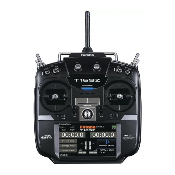
- Page 14 ● Monitor LED ● Antenna ● Carrying handle ● Dial LD.RD ● Switch ● Switch SA.SB.SE.SF SC.SD.SG.SH ● Slide lever ● Slide lever ● Stick ● Stick ● Power Switch ● Digital trim T1-T4 ● Hook ● HOME/EXIT Button ● U.MENU/MON. Button (User menu/Servo monitor)...
- Page 15 If you fly with your Low power transmitter facing the model at the angle shown in the illustration, High power High power bend the antenna 90 degrees. Do not fly your model with the antenna's tip pointing in its direction. CAUTION The antenna can be rotated 180 degrees and angles 90 degrees.
- Page 16 SF : 2 positions; Alternate; SH : 2 positions; Momentary; Long lever Long lever SE : SG : 3 positions; Alternate; 3 positions; Alternate; Short lever Short lever SA : SD : 3 positions; Alternate; 3 positions; Alternate; Short lever Short lever SB : 3 positions;...
- Page 17 analog input. knob reaches the center position. *You can use each setting screen of the mixing functions to select volumes and define the direction of movement. *You can select a slide lever and set the movement direction on the setting screen of mixing functions. <...
- Page 18 referencing the LCD screen. *You can select the trim step amount and the display unit linkage menu. *Example Stick Mode2 ◆When the airplane goes up while the ◆When the airplane dives while the elevator stick is neutral. elevator stick is neutral. ◆Elevator trim to up ◆Elevator trim to down Elevator Neutral...
- Page 19 ③ Connect the battery connector. ① A side battery cover is opened. Battery cover ④ Close the battery cover completely. ② Install the battery into the transmitter. This 2P connector connects HT5F1800B to the transmitter. NiMH Battery < Before Use >...
- Page 20 Do not use the transmitter the transmitter. as it is. Send it to the Futaba service center. 2. Plug the charger into an AC outlet. 3. Check that the charging LED lights.
- Page 21 T16SZ. Power Switch Power Switch Power Switch Throttle Stick Low Right or Left Long Push Right and Left Push Right or Left Long Push Tap this to stop the alarm a n d R F s i g n a l . O n l y p a n e l...
- Page 22 Tapping the settings buttons for each value on the settings screen data. will cause value input buttons to appear at the top of the panel. be careful so that you don't scratch the Touch Panel Pressing and holding a value will return it to its default setting.
- Page 23 CAUTION The T16SZ's touch screen is very sensitive. To avoid accidentally activating it during a flight, it is suggested that it be locked. Due to the touch screen's sensitivity, allowing it to be touched...
- Page 24 *Example Stick Mode2 < Before Use >...
- Page 25 *Example Stick Mode2 A general model example. (There is also a different operational model.) Roll Axis Control Pitch Axis Control Right roll Nose Up The right aileron is up. Elevator stick The left aileron Aileron stick is down. To the right (moved to the bottom) Elevator is Level flight...
- Page 26 *Example Stick Mode2 A general model example. (There is also a different operational model.) Roll Axis Control Pitch Axis Control Right roll Nose Up Elevator stick Aileron stick To the right (moved to the bottom) Level flight Level flight Neutral Neutral Left roll Elevator stick...
- Page 27 *Example Stick Mode2 A general model example. (There is also a different operational model.) Roll Axis Control Pitch Axis Control Right roll Nose Up Right slide Elevator stick Aileron stick Back slide To the right (moved to the bottom) Hovering Level flight Hovering Level flight...
- Page 28 Lever head Lever head Side cover 3. Using your hand remove the transmitter's rear head "A" counter-clockwise. The lock will be rubber grips. released. 2. Turn the lever-head "A" clockwise as you hold *It is difficult to remove rear grips from the central site of a transmitter.
- Page 29 (Mode 1) •Stick Tension (J2) (Mode 2) The T16SZ transmitter model data can be stored by using any commonly found SD card. When capable of using SD and SDHC cards (SD:32MB-2GB SDHC:4GB-32GB). Saving model data and update files (released When you have a problem of saving or reading from Futaba) into the SD card, you can use those card.
- Page 30 As the SD card is a precision device, do Battery cover not use excessive force when inserting. -When an SD card is installed in the T16SZ transmitter, a folder called "Futaba" is cre- folder stores the telemetry log data. -The telemetry log data recorded on the SD...
- Page 31 When using an S.BUS servo and telemetry sensor, connect them both here. Earphone Connecting a stereo headphone to this plug, the Plug speech information of telemetry can be heard. Charge Plug This is the connector for charging the NiMH battery HT5F1800B that is installed in the transmitter.
- Page 32 DANGER Before using the receiver, be sure to read the Don't attach a connector as shown in the preceding illustration. *It will short-circuit if connected in this way. A short circuit across the battery terminals may cause abnormal heating, fire and burns. WARNING S.BUS2 connectors Don't connect an S.BUS servo / gyro...
- Page 33 DANGER Don't touch wiring. * There is a danger of receiving an electric shock. Do not short-circuit the battery terminals. * A short circuit across the battery terminals may cause abnormal heating, fire and burns. Please double check your polarity ( +...
- Page 34 *Must be kept as straight as possible. Antenna Coaxial cable R7008SB Receiver This is not a critical figure, but the most To obtain the best results of the diversity important thing is to keep the antennas away from each other as much as possible. instructions: Larger models can have large metal 1.
- Page 35 Wood screw 2.3-2.6mm nut washer Rubber Rubber WARNING grommet grommet Brass eyelet Brass eyelet Servo mount Connecting connectors Servo mount 2.3-2.6mm screw Be sure to insert the connector until it stops at the deepest point. (Airplane/Glider) (Helicopter) How to protect the receiver from vibration and water To prevent the servo lead cable from being Wrap the receiver with something...
- Page 36 number of servos used. S.BUS Glider usage example Receiver: R7008SB Servo: S3174SV×9 ( Optional ) HUB×4 ( Optional ) Throttle servo: BLS173SV ( Optional ) Battery: FR2F1800 ( Optional ) S.BUS Aerobatic plane usage example Switch Receiver: R7008SB Aileron servo: BLS174SV×2 ( Optional ) HUB×3 ( Optional ) Rudder Servo: BLS175SV×1 ( Optional ) Elevator servo: BLS173SV×2 ( Optional )
-
Page 37: Power Supply
*When using 8/SB as S.BUS, you must set the receiver to Mode B or Mode D. See ●S.BUS Servo R7008SB CH MODE TABLE Page 33 Since the channel number is memorized by the S.BUS itself, any connector can be used. When the SBD-1, SBD-2 (sold separately) is used, ordinary servos can be used with the S.BUS system. - Page 38 When using the S.BUS2 port, an impressive array of telemetry sensors may be utilized. S.BUS2 TABLE S.BUS2 S.BUS Servo Servo Receiver port Telemetry sensor S.BUS2 S.BUS Gyro Gyro S.BUS ○ ○ × S.BUS2 × (※) ○ ○ (※)Don't connect S.BUS Servo, S.BUS Gyro to S.BUS2 connector.
- Page 39 S.BUS/S.BUS2 servos or a telemetry sensor can be connected directly to the T16SZ. Channel setting and other data can be entered for the S.BUS/S.BUS2 servos or sensors. 2. Turn on the transmitter power. 3. Call the setup screen. Servo: System Menu...
-
Page 40: Basic Operation
BASIC OPERATION This is the Home screen and descriptions of its menus. Use your finger to operate the touch screen. Battery voltage for receivers Condition name Battery Indicator • In FASSTest/T-FHSS mode, it is • The condition name • When the battery voltage displayed. - Page 41 Each transmitter has an individually assigned, unique ID code. In order to start operation, the receiver must be linked with the ID code of the transmitter to which it is being paired. Once the link is made, the ID code is stored in the receiver and no further linking is necessary unless the receiver is to be used with another transmitter.
- Page 42 setup a "Rx1" and "Rx2" in the "dual" mode. 9. ACT will be chosen if telemetry is used. It is INH when not using it. *Telemetry function cannot be used for the 2nd receiver. → FASSTest18CH *Telemetry function cannot be used for the dual receiver.
- Page 43 ◆ When the receiver has the transmitter's ID in memory, a link is established and normal operation is allowed. ◆ When the transmitter has the receiver's ID in memory, a link is established and telemetry functions are usable. The transmitter stores receiver IDs by model; thus, if it does not have a particular receiver model ID stored in memory or has a different receiver ID stored, telemetry functions will be unusable.
- Page 44 "HOME/EXIT" button. NEVER start flying when the "Range check mode" is active. Should you require additional time to perform a range 3. T16SZ Power ON. check, highlight Restart before your time expires and tap 4. Select "Range check" at the System menu.
- Page 45 MODEL BASIC SETTING PROCEDURE Initial setting assigns 1 model to the T16SZ transmitter. The Model Select function is used to add models and to select models which are already set. the direction with the Reverse function of the Linkage menu.
- Page 46 This function is used when an air brake is necessary when taking off or diving, etc. offset amount can be activated by a switch. The offset amount of the aileron, elevator, and flap servos can be adjusted as needed. Also the speed of the aileron, elevator, and flap servos can be adjusted.
- Page 47 Default setting assigns 1 model to the T16SZ. To add new models or to call a model already set, use the Model per model. select function. The Condition select function automatically allocates This is convenient when calling a model after (General setting) registering the model names in advance.
- Page 48 For a description of the connection method, see "Servos connection by model type". Note: The channel assignment of the T16SZ is different from that of our existing systems. (The channel assigned to each function can...
- Page 49 º as standard. º *If throttle hold is necessary, please refer to the Throttle hold function. The high side pitch setting is less than idle up 1. The standard is +8º. Throttle cut provides an easy way to stop the engine, by flipping a switch with the throttle stick at idle.
- Page 50 The T16SZ transmitter channels are automatically assigned for optimal combination according to the type selected with the Model type function of the Linkage menu. The channel assignment (initial setting) for each model type is shown below. Connect the receiver and servos to match the type used.
- Page 51 Ailevator 1AIL 2AIL 2AIL+1FLAP 2AIL+2FLAP 2AIL+4FLAP 4AIL+2FLAP 4AIL+4FLAP Airplane Glider Airplane Glider Airplane Glider Airplane Glider Airplane Glider Airplane Glider Airplane Glider Aileron Aileron Aileron Aileron Aileron Aileron Aileron Aileron Aileron Aileron Aileron Aileron Aileron Aileron Elevator Elevator Elevator Elevator Elevator Elevator Elevator...
- Page 52 Tailless wing 2AIL 2AIL+1FLAP 2AIL+2FLAP 2AIL+4FLAP 4AIL+2FLAP 4AIL+4FLAP Airplane Glider Airplane Glider Airplane Glider Airplane Glider Airplane Glider Airplane Glider Aileron Aileron Aileron Aileron Aileron Aileron Aileron Aileron Aileron Aileron Aileron Aileron AUX4 AUX4 AUX4 AUX4 AUX4 AUX4 Aileron2 Aileron2 Aileron2 Aileron2 Aileron2...
- Page 53 Tailless wing inglet 2 Rudder 2AIL 2AIL+1FLAP 2AIL+2FLAP 2AIL+4FLAP 4AIL+2FLAP 4AIL+4FLAP Airplane Glider Airplane Glider Airplane Glider Airplane Glider Airplane Glider Airplane Glider Aileron Aileron Aileron Aileron Aileron Aileron Aileron Aileron Aileron Aileron Aileron Aileron Rudder2 Rudder2 Rudder2 Rudder2 Rudder2 Rudder2 Aileron2 Aileron2...
- Page 54 FASSTest 18CH / FASST MULTI / FASST 7CH / S FHSS H-4/H-4X Swash All other Aileron Aileron Elevator Elevator Throttle Throttle Rudder Rudder Gyro Gyro Pitch Pitch Governor Governor Elevator2 Governor2 Gyro2 Gyro2 Gyro3 Gyro3 Governor2 Needle Needle AUX5 AUX4 AUX3 AUX2 AUX1...
- Page 55 Multicopter Aileron Elevator Throttle Rudder Gyro Gyro2 Gyro3 Camera TILT Camera PAN Camera REC Mode AUX5 AUX4 AUX3 AUX2 AUX1 SW SD SW SD SW SA < Model Basic Setting Procedure >...
-
Page 56: System Menu
SYSTEM MENU The System menu sets up functions of the transmitter. This does not set up any model data. [Display]: Display adjustment. [Sound volume]: Adjust the volume of: Other sound, Warning, Voice [System timer]: Resets the system timer. [H/W setting]: Stick mode selection (Mode 1 - Mode 4 ). J1-J4 sticks correction can be performed. [Battery] : Battery alarm voltage setting. - Page 57 Display The following LCD screen adjustments: Backlight max. brightness adjustment Touch calibration becomes darker. Backlight min. brightness adjustment becomes darker. *In ordinary operation, this calibration is not necessary. If *It cannot be made brighter than Backlighting brightness you notice the Touch Panel is not functioning correctly after adjustment.
-
Page 58: Sound Volume
", the volume will decrease. System timer *The system timer is displayed on the Home screen. This function adjusts the system timer of the T16SZ transmitter. The system timer can also be reset. ● Total : Regardless of a model, additional time in case a power supply is ON is displayed. - Page 59 But, it isn't changed until data is reset. the center of a stick should arise after prolonged use. To change the mode the stick ratchet must be changed. Request that this be done by Futaba Service. (Charged MODE1 MODE2 MODE3...
-
Page 60: Range Check
Battery Select the battery alarm voltage according to the battery to be used. It isn't indicated in case of manual setting. Battery type change : LiFe(2cells) → NiMH(5cells) → Manual setting When choosing manual setting, the numerical value can be input. It's dangerous to set it manually in the low voltage. - Page 61 An S.BUS(2) servo can memorize the channel and various settings you input. Servo setting can be performed on the T16SZ screen by wiring the * With some S.BUS(2) servos, there are some functions which cannot be used. If a function cannot be used, the display screen will change.
- Page 62 S.BUS Servo Description of each parameter's function *There are functions that can and cannot be performed according to the servo type. • ID Displays the ID of the servo whose parameters are to be read. It cannot be changed. • Channel Channel of the S.BUS system assigned to the servo.
- Page 63 • Boost ON/OFF OFF : It is the boost ON at the time of low-speed operation.(In the case of usual) ON : It is always the boost ON.(When quick operation is hope) • Damper The characteristic when the servo is stopped can be set. When smaller than the standard value, the characteristic becomes an overshoot characteristic.
- Page 64 Information This function registers the T16SZ user name The Information screen displays the T16SZ and the language displayed at proportional can be system program version information, SD card changed. (memory size, card free size) information. *If an SD card is not inserted, no memory card information Telemetry numerical values can be displayed in will be displayed.
- Page 65 LINKAGE MENU < Linkage menu >...
-
Page 66: Servo Monitor
Servo monitor Test mode change : OFF → Neutral → Moving < or > ● Long press the [U.MENU/ M O N . ] b u t t o n i n t h e Home screen to call the setup screen shown. -
Page 67: Model Select
Model select ● When model data on a SD card is used, this icon appears. < or > ● Tap the [Model select] b u t t o n i n t h e H o m e screen to call the setup screen shown below. - Page 68 Model call Model deletion (The model currently selected cannot be deleted.) Blue model would be deleted. Blue model was deleted. < Linkage menu >...
- Page 69 Model name change Model copy Current model (green) is chosen (blue). Current model (green) is chosen (blue). When you are done renaming, tap Model name. Completion of rename WARNING add new copied model Never launch the Model Selection function while the engine is starting or the motor drive wiring is connected.
-
Page 70: Model Type
Model type ( The display screen is an example. The screen depends on the model type.) Model type selection → 2. [Yes], tap 1. [Enter], tap < Linkage menu >... - Page 71 Set the type you choose by tapping. Airplane/Glider : Choose the Helicopter : Choose the wing type and tail. swash type. < Linkage menu >...
-
Page 72: Servo Reverse
Servo Reverse WARNING Before a flight, always check that your model's servo operation, the direction of control surfaces, and switch setup are correct. Default setting of the throttle/motor channel is always reverse. Tap the channel you wish to reverse. (The display screen is an example. The screen depends on the model type.) Tap the Yes →... -
Page 73: End Point
End point 30 ∼ 30 ∼ 140% 140% Travel rate Limit point Next page Ch7-16 Tap the values you wish to adjust and value input buttons will appear on-screen. Left / Top Right / Bottom Indicates the current direction of the stick, etc. (The display screen is an example. -
Page 74: Servo Speed
Servo speed (First) 0 ∼ 27 (Slowly) Servo speed setting Sub-trim Sub trim adjustment < Linkage menu >... - Page 75 Function DG1, DG2 (switch channels) Channel restrictions by a System Type Function change Operation control change < Linkage menu >...
- Page 76 Trim change reverse The Motor function is used when switching the motor ON/OFF (mostly for motor gliders). For most EP planes, the throttle can be left as-is when controlling the motor by stick. This means that the various throttle-related functions are usable via motor control.
-
Page 77: Fail Safe
Fail safe Do not continue to y. Land as soon as possible. WARNING For safety, always set the fail safe functions. ■ Especially set the throttle channel fail safe function so that the servo moves to the maximum slow side for airplanes and to the slow side from the hovering position for helicopters. -
Page 78: System Type
System type Dual receiver function (only FASSTest 18CH ) System Type selection Telemetry function (FASSTest /T FHSS mode only) Receiver linking DL Interval (FASSTest/T FHSS mode only) Linking method Battery fail safe voltage setup (FASSTest / P.41 T FHSS mode only) ・... - Page 79 The example for choosing System Type -Want to use a -Want to use an miniature receiver T-FHSS system -Response speed has -Want to use a -Want to use an for indoor planes receiver priority over number previously used S-FHSS system of channels receiver as is miniature receiver...
- Page 80 Trim setting Control step amount setting Separate/combination mode selection [Comb.] [Separ.] ▲▲ ▲ ▼▼ ▼ < Linkage menu >...
-
Page 81: Throttle Cut
Throttle cut − Tapping this will change − " INH to either OFF or ON and activated. The yellow line is the cut position. When This is the throttle cut the cut switch is ON, position. Tapping this the throttle will move will display value input to this position. - Page 82 Idle down Tapping this will change −− " INH to either OFF or ON and activated. T h i s i s t h e i d l e d o w n throttle position. Tapping this will display value input buttons on-screen.
-
Page 83: Swash Ring
Swash ring Setting the function to "ACT" will display the swash ring and [Rate] The movement range percentage. display shows control input for elevator and aileron direction. The marker represents the stick's position. Swash ring setting procedure < Linkage menu >... - Page 84 Swash Neutral Point Mixing Rate Linkage Compensation Swash AFR Speed Compensation < Linkage menu >...
- Page 85 Linkage correction setting procedure Neutral point setting procedure Swash AFR setting procedure Speed compensation setting procedure Mixing rate setting procedure Notes: < Linkage menu >...
- Page 86 Stick alarm Tapping this will change INH to ON and activated. If the throttle stick reaches the yellow l i n e , a n a l a r m w i l l sound. T h i s i s t h e c u r r e n t This is the throttle stick position display bar for alarm position.
- Page 87 Timer Last twenty seconds Last ten seconds Target time Time : Two short Continue counting One short Alarm : Also beeps with displaying a beep minus (-) sign. beep Elapsed: Minute-by-minute alarm starting from 00:00 Remainder : Minute-by- minute alarm counting down from a designated time A Buzzer or Speech can be chosen...
- Page 88 Integration Timer When a throttle stick is the high side, the speed of the timer usually increases. High When a throttle stick is middle-speed, the timer speed decreases (by 50%). Middle When a throttle stick is low, timer progress stops. INT Time Nomal Timer INT time (%)
- Page 89 Function name Function name change method < Linkage menu >...
-
Page 90: Telemetry System
P.97 voltage. Using various optional Optional telemetry sensors are necessary. P.92 telemetry sensors. T16SZ setting is unnecessary. Using several telemetry Setting by "sensor" in the menu is necessary. P.93 sensors of the same type. (Register is necessary.) Setting alarms from the Setting by "Telemetry"... - Page 91 Home display HOME/EXIT is pushed 4 of telemetry data is displayed *Be aware that pressing and holding this activates the key lock Y o u c a n c h o o s e which type of sensor t o d i s p l a y f o r f o u r displays.
- Page 92 Sensor [ hat is a slot ] sensors slot slots No. 1 No. 31 Altitude sensors, GPS sensors multiple slots start slot Slot Number Registered sensor Sensor ID : Multiple usage of sensors Tap the slot to display This is what displays when no of the same type requires an ID sensors which can be used s e n s o r i s r e g i s t e r e d i n a s l o t .
- Page 93 This page is set when using multiple telemetry sensors of the same type. Sensor:Reload Reading all the sensors to be used Sensor : Register This page is set when using multiple telemetry sensors of the same type. Receivers Battery Additional sensor registration <...
- Page 94 This page is set when using multiple telemetry sensors Sensor : Change slot of the same type. Receivers Battery Sensor slot change + ( WARNING ) Do not disconnect or turn transmitter power OFF while telemetry sensor data is being saved. Sensor save data will be lost, resulting in malfunction.
- Page 95 Telemetry T a p p a g e b u t t o n t o advance to next page. ( The number of pages changes with the number of sensor registration.) Various telemetry data Start slot number Choose the desired sensor and tap. Max.
- Page 96 Telemetry: Receiver [Battery] Receiver battery voltage Max. and min. values s i n c e t h e p o w e r was turned ON will display. ↓ The "down" arrow will indicate that an alarm will sound when Sets the voltage on the voltage drops to which the alarm...
- Page 97 Telemetry: Receiver [Ext. battery] *CA-RVIN-700 must be installed in the aircraft. Ext. battery voltage Max. and min. values since the power was turned ON will display. ↓ The "down" arrow will indicate that an alarm will sound when Sets the voltage on the voltage drops to which the alarm below the setting.
- Page 98 Telemetry : Temperature *A temperature sensor must be installed in the aircraft. Temperature Max. and min. values s i n c e t h e p o w e r was turned ON will display. ↑ An upward arrow w i l l s h o w t h a t a n alarm will sound when the temperature rises above the set value.
- Page 99 Telemetry : RPM Sensor *An rpm sensor must be installed in the aircraft. Max. and min. values s i n c e t h e p o w e r was turned ON will display. ↑ An upward arrow will show that an alarm will sound when the rpm rises above the set value.
- Page 100 Telemetry : Altitude *An altitude sensor or GPS sensor must be installed in the aircraft. Altitude Max. and min. values s i n c e t h e p o w e r was turned ON will display. Sets the altitude ↑...
- Page 101 Telemetry : Altitude [Variometer] *An altitude sensor or GPS sensor must be installed in the aircraft. Variometer Max. and min. values s i n c e t h e p o w e r was turned ON will display. Sets the variometer ↑...
- Page 102 Vario Melody Setting Tap the [Set] button Current variometer *These settings can be made for each sensor. Next page Range Deadband Setting range: Setting range: Setting range: ∼ Initial value: Setting range: ∼ ∼ ∼ Initial value: Initial value: Initial value: Offset Fixed melody Range↑...
- Page 103 Delay Setting range: , , , Initial value: *This parameter is effective to all variometers. Actually Variometer 0.0m/s 1.0m/s 3.0m/s 4.0m/s 2.0m/s -1.0m/s Output Vario Melody 0.0m/s 1.0m/s 3.0m/s 4.0m/s 2.0m/s -1.0m/s Delay time 1.0s < Linkage menu >...
- Page 104 Telemetry: Voltage [Battery] *SBS-01V must be installed in the aircraft. ⇔ ⇔ Battery voltage Max. and min. values s i n c e t h e p o w e r was turned ON will display. ↓ The "down" arrow will indicate that an alarm will sound when Sets the voltage on...
- Page 105 Telemetry: Voltage [Ext. battery] *SBS-01V must be installed in the aircraft. ⇔ ⇔ Ext. battery voltage Max. and min. values s i n c e t h e p o w e r was turned ON will display. ↓ The "down" arrow will indicate that an alarm will sound when Sets the voltage on...
- Page 106 Telemetry : GPS [Distance] *A GPS sensor must be installed in the aircraft. Distance Max. and min. values s i n c e t h e p o w e r was turned ON will display. ↑ An upward arrow indicates the alarm will sound when the d i s t a n c e r e a c h e s...
- Page 107 First, the set of a reference is re uired. Setting a too close alarm distance Setting a too far alarm distance ≧ ≧ Telemetry Data Positioning time of GPS < Linkage menu >...
- Page 108 Telemetry : GPS [Speed] *A GPS sensor must be installed in the aircraft. Max. and min. values Speed s i n c e t h e p o w e r was turned ON will display. ↑ An upward arrow indicates the alarm will sound when the speed reaches above...
- Page 109 Telemetry : GPS [Altitude, Variometer, Position] *A GPS sensor must be installed in the aircraft. Max. and min. values s i n c e t h e p o w e r was turned ON will display. Altitude Variometer Refer to the former p a g e f o r a s e t u p about Altitude and Variometer.
- Page 110 Telemetry : Servo sensor [Current] *Servo sensor must be installed in the aircraft. Tap here and go to the Servo 2 settings page. (Display and settings content is the same as Servo 1.) Max. and min. values Tapping this will s i n c e t h e p o w e r take you to the was turned ON will...
- Page 111 Telemetry : Servo sensor [Temperature] [Angle] *Servo sensor must be installed in the aircraft. ● Temperature ↑ An upward arrow indicates the alarm will sound when the temperature reaches above your set value. ↓ A downward arrow Sets the temperature indicates the alarm on which the alarm will sound when the...
- Page 112 Telemetry : Current sensor [Current] *Current sensor must be installed in the aircraft. Tapping this will take you to the settings screen for the current alarm Max. and min. values since the power Tapping this will take you to was turned ON will the settings screen for the display.
- Page 113 ■ Extension FLD: Log data file *When copying or moving a log file, always select both the .FLI file and .FLD file. Log files can be converted to CSV format by using the telemetry log converter available at the Futaba website. ■ Notes ◇...
- Page 114 Telemetry Alarm Duration and Repeat time The repeat time and duration time for the telemetry alarm (buzzer, vibration and speech) can be set. Duration is not displayed when Repeat is INH. Duration Repeat It is an alarm output time. It is a repeat time of an alarm Setting range:1 s ∼...
- Page 115 Trainer Note: Corresponding types of transmitters and trainer mode settings: < Linkage menu >...
- Page 116 hen using at the student side hen using at the teacher side < Linkage menu >...
- Page 117 Trainer student channel setting function < Linkage menu >...
- Page 118 Warning setting The settings can be changed "Vibrator" type individually. When set to If the following types are selected, the transmitter [Inhibit], a warning is not will vibrate during the warning. displayed at power ON. Type 1 Type 2 Type 3 WARNING It is extremely dangerous to unnecessarily inhibit essential...
- Page 119 User menu setting Tap here to select your first choice. Once pressed, 3 pages of choices will be displayed. When "---" is chosen, it can be deleted. Make your selection, press your choice and the first of your "User menu" will be entered. How to call a User menu From the home screen...
-
Page 120: Data Reset
Data reset Model menu setting: All model setting: Trim (All condition): Function Name: Trim (Current and Group condition): Telemetry: Data resetting method CAUTION CAUTION Never engage the Data reset function Throttle Reverse while the engine is starting or the ■ Only the throttle channel (CH3) initial setting is motor drive wiring is connected. - Page 121 MODEL MENU (Common functions) Note: The T16SZ is designed so that the airplane and glider model types are compatible with aircraft of similar type wings. This section outlines the relationship between the functions common to airplanes and gliders, except some dedicated functions, and model type.
- Page 122 Flight condition's addition, deletion, copy, condition renaming, Condition select and condition delay can be set. [All model types] when there are sudden changes in the servo positions and when there are variations in the operating time between channels during condition switching can be suppressed. The delay can be set for each channel.
- Page 123 Currently selected condition name The ON/OFF switch of Conditions List condition is chosen. Condition Copy Condition Remove 1 . S e l e c t t h e c o n d i t i o n b y appears. tapping the condition you 2.
- Page 124 The angle and curve of each operation function can be set. [All model types] Rate 100% of curves (EXP1, EXP2, and Point) can be used for the point curve type. (Initial setting: 9 points) The number of points can also be increased and decreased and curves from complex curves to simple curves can be Rate...
-
Page 125: Dual Rate
Dual rate 100% condition. call the setup screen shown below. The ON/OFF switch of dual rate is chosen. Activate the D/R function When the function select button by tapping the [INH] . is tapped, a selection screen appears. Select the function you want to set at the selection screen. - Page 126 Program. mixes mixings can be used for each condition. [All model types] the setup screen shown below. ● Group/single mode switch (Gr./Sngl) (For more information, see the description at the back of this manual.) After this function is Mixing/Offset mode activated, the master switch and slave function...
- Page 127 Setting methods button on the screen. Activating functions for only the selected conditions: mode. Using the offset mode: 1. Tap the curve type selection button of the curve type you want to use to display the selection screen. Then, select the curve you want to use.
- Page 128 Model menu functions section. First use (Up to 8 conditions can be used) Note: The T16SZ is designed so that the airplane and the Model type function of the Linkage menu to glider model types can handle aircraft of the same preset the model type, wing type, and tail type wing type.
-
Page 129: Camber Mixing
Camber mixing Air brake This mix adjusts the camber and corrects the This function is used when airbrakes are necessary when landing or when diving, etc. during flight. elevators. [Airplane/glider, 2 ailerons or more] [Airplane, general] Airbrake Gyro This mix is used to correct operation of the airbrakes (spoilers) when landing. - Page 130 [Airplane/glider, 2 ailerons or more] Aileron differential The left and right aileron differential can be adjusted independently. The differential rate can also be adjusted according to the flying state by AIL1 AIL 2 (Main Aileron) (Main Aileron) AIL 3 AIL 4 (Chip Aileron) (Chip Aileron) menu and call the setup screen shown...
- Page 131 [Corresponding model type]: Airplane/ Flap setting The up/down travel of each flap (camber flaps: FLP1/2, brake flaps: FLP3/4) can be adjusted independently at each servo according to the wing type. FLP 4 FLP 3 (Brake Flap) offset (Brake Flap) FLP 1 FLP 2 (Camber Flap) (Camber Flap)
- Page 132 [Corresponding model type]: Airplane/ AIL → Camber flap This mix operates the camber flaps (FLP1/2) in the aileron mode. When the aileron stick is manipulated, the ailerons and camber flaps perform aileron operation simultaneously and the operation characteristic of the roll axis is FLP 1 FLP 2 (Camber Flap)
- Page 133 [Corresponding model type]: Airplane/ AIL → Brake flap This mix operates the brake flaps (FLP3/4) in the aileron mode. When the aileron stick is manipulated, the aileron and brake flaps perform the aileron operation simultaneously FLP 4 FLP 3 (Brake Flap) (Brake Flap) and the operation characteristic of the roll axis is improved.
- Page 134 [Corresponding model type]: Aileron → Rudder Airplane/glider, general Use this mix when you want to mix the rudders with aileron operation. AIL1 AIL 2 (Main Aileron) (Main Aileron) AIL 3 AIL 3 (Chip Aileron) (Chip Aileron) RUDDER 2 RUDDER 1 Winglet Winglet at Flying wing...
- Page 135 [Corresponding model type]: Airplane/glider, 2 ailerons or more Elevator → Camber Note: Tailless wing elevator can be operated This function is used when you want to mix the when this mix is activated. be increased. menu and call the setup screen shown Currently selected condition name below.
- Page 136 [Corresponding model type]: Airplane/glider, 2 ailerons or more Camber mixing This function adjusts the rate of camber operation which operates the wing camber adjustments can be made by changing the (ailerons, camber flaps, brake flaps) in the negative and positive directions. The aileron, flap, and elevator rates can also be adjusted independently by curve, and attitude changes caused by camber operation can be corrected.
- Page 137 Setting method the aileron, flap, and elevator curve/rate screens. of the switch and tap the screen to call the The rate and curve of each servo can be set selection screen, and then select the switch the curve setting method, see the description The servo speed can also be adjusted.
- Page 138 [Corresponding model type]: Airbrake → ELE Airplane/glider, general AIR BRAKE This mix is used when you want to mix the elevators with airbrake (spoiler) operation. It raises the elevators to correct for dropping of the nose during airbrake operation. AILVATOR V-TAIL *This function does not operate when airbrake is not assigned at the Function menu in the Linkage menu.
- Page 139 [Corresponding model type]: Airplane/ Camber flap → ELE glider, This mixing is used to correct changes (elevator FLP 1 FLP 2 (Camber Flap) (Camber Flap) AILVATOR V-TAIL ELEVATOR ELEVATOR ELEVATOR 2 ELEVATOR 2 menu and call the setup screen shown Currently selected condition name below.
- Page 140 [Corresponding model type]: Rudder → Aileron Airplane/glider, general This function is used when you want to mix the ailerons with rudder operation. It is used when rudder is applied during roll maneuvers, AIL1 AIL 2 (Main Aileron) (Main Aileron) knife edge, etc. of stunt planes. It can be used to AIL 3 AIL 3 (Chip Aileron)
- Page 141 [Corresponding model type]: Airplane, general Rudder → Elevator This function is used when you want to mix elevator operation with rudder operation. It is used to correct undesirable tendencies when rudder is applied in roll maneuvers, knife edge, etc. of acrobatic planes.
- Page 142 [Corresponding model type]: Glider, 2 ailerons or more Butterfly This function allows powerful brake operation by simultaneously raising the left and right ailerons and lowering the flaps (camber flap, item selected when operated to the position to This setting will allow the ailerons to be raised reference point is offset too much, unexpected while the flaps are simultaneously lowered.
- Page 143 Select the Mixing Rate AIL and FLP box. Adjust the mixing rates. Elevator rate adjustment (To elevator curve setup screen) (Elevator correction rate setup screen) The offset position is indicated by a red dotted line by an elevator curve. Overall adjustment by Rate A and Rate B Mixing curve setting *For a description of the curve setting method,...
- Page 144 [Corresponding model type]: Glider, general Trim mix 1/2 Example These functions call the ailerons, elevators, and Set the trim mix function to The amount of ailerons, elevator, and flaps *When separating the settings for each condition, move to the [Group] item and set it to [Single]. a switch.
- Page 145 [Corresponding model type]: Airplane, general Snap roll (Example) Setting example for F3A This function selects the switch and rate adjustment of each rudder, (ailerons, elevators, or *The snap roll up side left and right and down side left and right direction switches are selected here. switch in the state in which the direction switch was switched to the direction in which you want roll in each direction can be executed by means...
- Page 146 Air brake This function is used when an air brake is necessary when landing or diving, etc. Elevator The preset elevators and flaps (camber flap, Aileron 2 brake flap) offset amount can be activated by a switch. Aileron 1 The offset amount of the aileron, elevator, and flap servos can be adjusted as needed.
- Page 147 [Corresponding model type]: Airplane/glider/multicopter, general Gyro This function is used when a GYA Series gyro *Initial setting does not assign a sensitivity channel. Use the Function menu of the Linkage menu to assign the sensitivity is used to stabilize the aircraft's attitude. The channel (Gyro/Gyro2/Gyro3) used to a vacant channel sensitivity and operation mode (Normal mode/GY beforehand.
- Page 148 (Example) Setting three axis using a G A44 and G A441 (2) : at 5CH → Gyro 7CH → Gyro2 8CH → Gyro3 Control and Trim → "--" Rate Type Switch Gyro Gyro 2 Gyro 3 OFF/ON AVCS : 60% AVCS : 60% AVCS : 60% ON/OFF...
- Page 149 [Corresponding model type]: Airplane/glider, Tail type Ailevator Ailevator (Effective only when 2 servos used at the elevators) T h i s f u n c t i o n i m p r o v e s t h e o p e r a t i n g performance of the roll axis by operating the elevators as ailerons.
- Page 150 [Corresponding model type]: Glider, general Acceleration Acceleration setting can be performed at Elevator, only) setting. The setting method is the same. side and down side. menu and call the setup screen shown below. Condition group/ To next page When using this single mode selection 2/3 : Elevator →...
- Page 151 [Corresponding model type]: Airplane/glider, general Motor This function lets you set the operation speed when the motor of an F5B or other EP glider is started by switch. The operation speed can be set in 2 ranges of slow speed flight and high speed operated as a safety function by setting 2 switches.
- Page 152 V-Tail This function lets you adjust for left and right rudder angle changes at elevator and rudder operation of a rudder movement as elevators. In addition to each ELEVATOR RUDDER rudder side moving up and down together, each side (RUDDER 2) (ELEVATOR 2) moves in opposite directions when moving as elevators.
- Page 153 Winglet This function adjusts the left and right rudder angles of airplanes with winglets. Winglets are used to improve the efficiency of wingtip vortices. The winglet is a vertical or angled RUDDER 1 Winglet extension at the tips of each wing. at Flying wing Winglets work by increasing the effective aspect RUDDER 2...
- Page 154 MODEL MENU (Helicopter functions) This section contains information on the Also, add flight conditions at the Condition commands that apply to helicopters only. For Select screen if necessary before setting the model instructions on airplane, glider and multicopter, data at each function. (Up to 8 conditions can be refer to the sections pertaining to those aircraft.
- Page 155 Pitch curve / Pitch trim *Up to 17 points can be set for the point curve types. This function adjusts the pitch operation curve create a curve, a simple curve can be created by reducing relative to movement of the throttle stick. the number of input points to 3 or 5, and then entering the a curve.
- Page 156 Setting method Curve setting examples *For a description of the curve setting method, see the The screens shown below are curves created description at the back of this manual. by entering the pitch rate at low, center, and high side (3 points or 5 points) at each condition. When the fuselage (or the reference value).
- Page 157 The hovering pitch, low pitch, and high pitch trim setup screen can be called from the Pitch curve setup screen. Hovering pitch trim Low/high pitch trim setting setting Hovering pitch trim High Pitch/Low Pitch Trim The Hovering Pitch trim function trims the pitch High Pitch/Low Pitch Trim is the pitch servo near the hovering point.
- Page 158 Throttle curve / Throttle Hover trim This function adjusts the throttle operation curve point data is used, a simple curve can be easily for each condition for optimum engine speed to created by reducing the number of input points of throttle stick movement.
- Page 159 Curve setting examples created by reducing the number of points on the The curves shown below are created by using line to 5. When actually creating a curve, enter the point curve type and inputting the data of the 5 points 0% (low side), 25%, 50% (center), 75%, value).
- Page 160 Acceleration This function is used to adjust the pitch and the throttle rise characteristic at acceleration/ deceleration operation. An acceleration function which temporarily increases the pitch and throttle operations at throttle stick acceleration/deceleration operation can be set. Example of acceleration function use W h e n u s i n g t h i s Condition group/ To next page...
-
Page 161: Throttle Hold
Throttle hold Example of use This function sets the throttle cut position for autorotation. The throttle position can also be set to an idling position. Setting of these 2 positions can be selected by switch. This allows use for switching during training. - Page 162 Swash mixing Example of use The swash mix function is used to correct the swash plate in the aileron (roll) direction and elevator (cyclic pitch) corresponding to each operation of each condition. Adjustment by independent curve for aileron, elevator, and pitch operations is possible. The operation can be smoothly adjusted by calling up the “Curve setup”...
- Page 163 Throttle mixing When correction is necessary, tap to the mixing item corresponding to the mixing that needs This function corrects slowing of engine speed correction and tap the screen to call the curve setup caused by swash plate operation during aileron screen, and then correct the slowing.
- Page 164 Pitch → Needle This mixing is used when the engine is equipped acceleration/deceleration operation can be set. with needle control or other fuel-air mixture The rise characteristic of the needle servo at adjustment. A needle curve can be set. acceleration and deceleration operation can be adjusted.
- Page 165 Pitch → Rudder (Revolution mixing) However, when a GY Series or other heading Use this mix when you want to suppress the hold gyro is used, since correction is performed reaction torque generated by main rotor pitch and by the gyro, this mix is not used. If this function speed changes during pitch operation.
- Page 166 Gyro [Helicopter] This function is used to adjust gyro sensitivity. The sensitivity and operation mode (Normal mode/ AVCS mode) can be set for each condition. CH10 The gyro sensitivity can be switched with each condition or the switch. (3 sensitivities) *Compatible with 3 axis gyro (CGY750). Gyro(RUD) Gyro2(AIL) Gyro3(ELE)
- Page 167 Usage example #1: Using gyro for only the rudder and adjusting sensitivity for each condition * Gyro gain channel Gyro : CH5 For the FASSTest12CH, Gyro/RUD is 6ch. The gyro sensitivity adjustment connector connects to 6ch. This is all that is needed for use in this case.
- Page 168 Governor When using a Futaba governor, this function is *When using the Fuel Mixture function, the mixture servo is controlled from the governor. When transmitting the used to switch the RPM of the helicopter's head. mixture curve data from the transmitter to the governor, the Up to 3 rates can be set for each condition.
- Page 169 *For a description of the switch selection method, see the governor. description at the back of this manual. * In order to use the Governor function of the T16SZ, it is necessary to change the settings on the governor for the low side 700 rpm mode.
- Page 170 Common operations used in function setup screen This section describes the functions often used at the function setup screen. Refer to it when setting each function. Tapping the value setting buttons on each screen will cause value input buttons to appear at the top of the panel. Value input buttons display at the top of the panel Pressing and holding...
- Page 171 Operation mode selection *The operation modes which can be selected depend on the function. VR selection Rate adjustment (Fine tuning VR operation position) [Fine tuning VR operation mode] When the VR is turned clockwise and <Hardware select> screen, and then select "...
- Page 172 Linear (First) 0 ∼ 27 ( Slowly) In case of Linear Speed In speed Servo speed setting The servo speed at each function operation (including flight condition switching) can be adjusted. The servos Out speed Speed operate smoothly at a fixed speed corresponding to the set speed.
- Page 173 This section describes the setting procedure of curves which are used with the AFR function and each mixing function. Curve type selection Four types of curves (EXP1, EXP2, Point and Spline) can be selected. Curve type selection < Data >...
- Page 174 Setting by curve type When the curve type is selected as described above, adjustment items corresponding to the curve type appear on the screen. Adjust each curve as described below. EXP1/EXP2 curve adjustment (When the value is tapped, the rate is reset to the initial value.) U s i n g t h e E X P 1 c u r v e i s e ff e c t i v e i n smoothing starting of the ailerons, elevator,...
- Page 175 Point curves or spline curves of up to 11/17 points can be used. (Initial value: 7/9 points) The set points can be freely increased, decreased, and offset. Point addition method The kind of mixing curve Point deletion method (■) The red point moves (to green point) Move between point...
- Page 176 Curve setting operation Spline curve Up to 11 or 17 points curve can be used. (differs with function) A smoother curve is made. Setting method is same at spline and point. Point Spline *The set points can be freely increased, decreased, and offset.
- Page 177 Point curve (Point) adjustment Normal setting Up to 11 or 17 points curve can be used. (differs with function) *The set points can be freely increased, decreased, and offset. and select the point whose *The mark on the curve shows the currently selected point.
- Page 178 The various functions used in the T16SZ can be selected by switch. The switch (including when stick, trim lever, or VR are used as a switch) setting method is common to all functions. Switch selection When a switch is selected at a mixing function, etc., the selection screen shown below is called.
- Page 179 Hysteresis-type and box-type can be selected in a hardware select screen. When a stick, trim lever, or VR is used as a switch, the following 4 modes can be selected. ◆ Linear・Hysteresis mode ◆ Symmetry・Hysteresis mode This setting method selects function ON/OFF based The operation is the same as the linear hysteresis on the set point.
- Page 180 When shifting the ON/OFF point ◆ Area Green:ON The ON/OFF and hysteresis (dead band) boundary point (there ◆ Area Red:OFF are 2 points: top and bottom) position can be shifted. ON/OFF is possible at a free position. ◆ Area Yellow:Hysteresis (Dead band) [ Setting method ] Reverse of ON/ OFF direction...
- Page 181 Logic switch (Condition select and DG1, DG2) The logic switch function lets you turn operation on and off by combining two switches. For instance, the condition is activated when 2 switches are turned on. Logic mode Switch mode selection Switch selection Logic mode selection <...
- Page 182 Your Futaba T16SZ transmitter programming can be updated easily online. When functions are added and then use the following procedure to update the program. Check our web site for the FAQ regarding updating for more information. Updating procedure The model data in the transmitter can...
- Page 183 In that case, please update again Complete Possible Problems < Data >...
- Page 184 T14SG/FX-22 T16SZ MODEL DATA CONVERSION The model data (only latest version) of T14SG/FX-22 can be copied to T16SZ. * SD card is required. * The model data of T16SZ cannot be copied to T14SG/FX-22. (a) First, update a T14SG or FX-22 to the latest software.