Juniper EX2300 Series Hardware Manual
Hide thumbs
Also See for EX2300 Series:
- Quick start manual (15 pages) ,
- Quick start (2 pages) ,
- Features manual (476 pages)
Table of Contents
Advertisement
Quick Links
Advertisement
Table of Contents
Troubleshooting

Related Manuals for Juniper EX2300 Series


Summary of Contents for Juniper EX2300 Series
- Page 1 EX2300 Switch Hardware Guide Published 2022-02-14...
- Page 2 The Juniper Networks product that is the subject of this technical documentation consists of (or is intended for use with) Juniper Networks software. Use of such software is subject to the terms and conditions of the End User License Agreement ("EULA") posted at https:/ /support.juniper.net/support/eula/.
-
Page 3: Table Of Contents
Table of Contents About This Guide | ix Overview EX2300 System Overview | 2 EX2300 Switches Hardware Overview | 2 EX2300 Switch Models | 15 EX2300 Switch Hardware and CLI Terminology Mapping | 18 Chassis Physical Specifications for EX2300 Switches | 23 EX2300 Chassis | 25 Chassis Status LEDs in EX2300 Switches | 26 Management Port LEDs in EX2300 Switches | 30... - Page 4 Requirements for Mounting an EX2300 Switch On or Under a Desk or Other Level Surface or On a Wall | 66 Clearance Requirements for Airflow and Hardware Maintenance for EX2300 Switches | 67 EX2300 Network Cable and Transceiver Planning | 75 Pluggable Transceivers Supported on EX2300 Switches | 75 SFP+ Direct Attach Copper Cables for EX Series Switches | 77 Understanding EX Series Switches Fiber-Optic Cable Signal Loss, Attenuation, and Dispersion | 79...
- Page 5 Installing and Connecting an EX2300 Switch | 104 Mounting an EX2300 Switch | 105 Mounting an EX2300 Switch on a Desk or Other Level Surface | 106 Mounting an EX2300-C Switch Under a Desk or Other Level Surface by Using Screws | 108 Mounting an EX2300 Switch on Two Posts of a Rack or Cabinet | 113 Mounting an EX2300 Switch on Four Posts of a Rack or Cabinet | 116 Mounting an EX2300 Switch on a Wall | 119...
- Page 6 Reverting to the Default Factory Configuration for the EX Series Switch | 179 Reverting to the EX Series Switch Factory-Default Configuration Using the request system zeroize Command | 180 Reverting to the EX Series Switch Factory-Default Configuration Using the load factory- default Command | 180 Reverting to the Factory-Default Configuration Using the EX Series Switch LCD Panel | 182 Reverting to the Factory-Default Configuration Using the Factory Reset/Mode button on...
- Page 7 Contacting Customer Support and Returning the Chassis or Components Returning an EX2300 Switch or Component for Repair or Replacement | 254 Returning an EX2300 Switch or Component for Repair or Replacement | 254 Locating the Serial Number on an EX2300 Switch or Component | 255 Listing the Switch and Components Details with the CLI | 255 Locating the Chassis Serial Number ID Label on an EX2300 Switch | 257 Contact Customer Support to Obtain Return Material Authorization | 257...
- Page 8 viii Action to Take After an Electrical Accident | 287 Prevention of Electrostatic Discharge Damage | 288 AC Power Electrical Safety Guidelines | 289 AC Power Disconnection Warning | 290 DC Power Electrical Safety Guidelines | 291 DC Power Disconnection Warning | 292 DC Power Grounding Requirements and Warning | 294 DC Power Wiring Sequence Warning | 294 DC Power Wiring Terminations Warning | 296...
-
Page 9: About This Guide
About This Guide Use this guide to install hardware and perform initial software configuration, routine maintenance, and troubleshooting for the EX2300 switch. After completing the installation and basic configuration procedures covered in this guide, refer to the Junos OS documentation for information about further software configuration. -
Page 10: Overview
C HAPTER Overview EX2300 System Overview | 2 EX2300 Chassis | 25 EX2300 Cooling System | 40 EX2300 Power System | 46... -
Page 11: Ex2300 System Overview
Juniper Networks EX Series Ethernet Switches provide scalable connectivity for the enterprise market, including branch offices, campus locations, and data centers. The Juniper Networks EX2300 Ethernet Switches run the Juniper Networks Junos operating system (Junos OS), which provides Layer 2 and Layer 3 switching, routing, and security services. - Page 12 Support for Juniper Networks Junos Fusion Enterprise—EX2300 switches can act as a satellite device to support a Juniper Networks Junos Fusion Enterprise deployment, which can combine several wiring closets into one logical management platform.
- Page 13 NOTE: You cannot form a Virtual Chassis by using SFP transceivers. For forming a Virtual Chassis, you must explicitly configure an uplink port on each of the switches to be connected as a VCP. See Setting an Uplink Port on an EX Series or QFX Series Switch as a Virtual Chassis Port.
- Page 14 NOTE: IEEE 802.3at class 4 powered devices require category 5 or higher Ethernet cables. The remainder of this topic uses the term PoE to refer to both PoE and PoE+ unless there is a need to distinguish between the two. Front Panel of an EX2300 Switch The front panel of an EX2300-C switch consists of the following components: •...
- Page 15 Figure 1 on page 6 shows the front panel of an EX2300-C switch with 12 Gigabit Ethernet ports with PoE capability and Figure 2 on page 6 shows the front panel of an EX2300-C switch with 12 Gigabit Ethernet ports without PoE capability. Figure 1: Front Panel of an EX2300-C Switch with 12 Gigabit Ethernet Ports with PoE Capability RJ-45 network ports Factory Reset/Mode button...
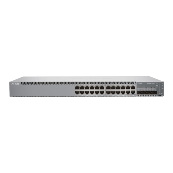
- Page 16 The front panel of EX2300 switches except the EX2300-C, EX2300-24MP, and EX2300-48MP switch models consists of the following components: • RJ-45 network ports—depending on the switch model, either of: • 24 10/100/1000 BASE-T Gigabit Ethernet ports without PoE capability in the EX2300-24T and EX2300-24T-DC models •...
- Page 17 Port status mode LEDs. The LED labeled PoE 10-Gigabit Ethernet uplink ports — — is present only on models with PoE capability. Figure 4: Front Panel of an EX2300 Switch with 48 Gigabit Ethernet Ports with PoE Capability Except the EX2300-48MP Model RJ-45 network ports Factory Reset/Mode button —...
- Page 18 • One USB port • One management port • One RJ-45 console port • 16 100/1000/2500 BASE-T Gigabit Ethernet ports with PoE/PoE+ capability • 32 10/100/1000 BASE-T Gigabit Ethernet ports with PoE/PoE+ capability • Six built-in 10-Gigabit Ethernet uplink ports. You can use these ports to forward network traffic or configure them into VCPs to interconnect EX2300 switches into a Virtual Chassis.
- Page 19 System LEDs Management port — — 10/100/1000 BASE-T Gigabit Ethernet ports Console port — — with PoE/PoE+ capability 100/1000/2500 BASE-T Gigabit Ethernet USB port — — ports Rear Panel of an EX2300 Switch The rear panel of an EX2300-C switch consists of the following components: •...
- Page 20 Protective earthing terminal — Figure 8: Rear Panel of an EX2300-C Switch with 12 Gigabit Ethernet Ports without PoE Capability CLEI code label Protective earthing terminal — — Serial number ID label AC power cord inlet — — The rear panel of the EX2300 switch except the EX2300-C, EX2300-24MP, and EX2300-48MP switch models consists of the following components: •...
- Page 21 NOTE: DC-powered EX2300 switches do not provide PoE. The AC power cord retainer clips in EX2300 switches except the EX2300-24MP model and the EX2300-48MP model extend out of the chassis by 3 in (7.62 cm). Figure 9: Rear Panel of an AC-Powered EX2300 Switch with 24 Gigabit Ethernet Ports with PoE Capability Except the EX2300-24MP Model USB port Air exhaust openings...
- Page 22 ESD point — Figure 11: Rear Panel of an AC-Powered EX2300 Switch with 24 Gigabit Ethernet Ports without PoE Capability USB port Air exhaust opening — — Management Ethernet port Serial number ID label — — RJ-45 console port CLEI code label —...
- Page 23 ESD point — Figure 13: Rear Panel of a DC-Powered EX2300 Switch with 24 Gigabit Ethernet Ports USB port Air exhaust opening — — Management Ethernet port Serial number ID label — — RJ-45 console port CLEI code label — —...
-
Page 24: Ex2300 Switch Models
Serial number ID label AC power cord inlet — — Figure 15: Rear Panel of an EX2300-48MP Switch CLEI code label AC power cord inlet — — Serial number ID label ESD point — — EX2300 Switch Models The EX2300 switch is available with 12 or 24, or 48 built-in RJ-45 network ports with full Power over Ethernet (PoE) or Power over Ethernet plus (PoE+) capability on all built-in RJ-45 network ports (access ports), or no PoE capability. - Page 25 (Continued) Table 1: EX2300 Switch Models Model Access Ports Virtual Chassis Ports in Which Maximum First License PoE Is Available System Junos OS Power Release Available for PoE/PoE+ EX2300-C-12T-VC 12 Gigabit Available – – 15.1X53- Ethernet EX2300-C-12T-TAA 12 Gigabit Not available –...
- Page 26 (Continued) Table 1: EX2300 Switch Models Model Access Ports Virtual Chassis Ports in Which Maximum First License PoE Is Available System Junos OS Power Release Available for PoE/PoE+ EX2300-24P-VC 24 Gigabit Available All 24 ports 370 W 15.1X53- Ethernet EX2300-24P-TAA 24 Gigabit Not available All 24 ports...
-
Page 27: Ex2300 Switch Hardware And Cli Terminology Mapping
EX2300 Switch Hardware and CLI Terminology Mapping This topic describes the hardware terms used in EX2300 switch documentation and the corresponding terms used in the Junos OS CLI. See Table 2 on page Table 2: CLI Equivalents of Terms Used in Documentation for EX2300 Switches Hardware Description (as Value... - Page 28 (Continued) Table 2: CLI Equivalents of Terms Used in Documentation for EX2300 Switches Hardware Description (as Value Item in Additional Information Item (as Displayed in the CLI) Document Displayed Displa ation in the CLI) yed in CLI) FPC ( Abbreviated name of Value The switch Understanding Interface Naming Conventions...
- Page 29 (Continued) Table 2: CLI Equivalents of Terms Used in Documentation for EX2300 Switches Hardware Description (as Value Item in Additional Information Item (as Displayed in the CLI) Document Displayed Displa ation in the CLI) yed in CLI) n is a PIC ( Abbreviated name of The switch...
- Page 30 (Continued) Table 2: CLI Equivalents of Terms Used in Documentation for EX2300 Switches Hardware Description (as Value Item in Additional Information Item (as Displayed in the CLI) Document Displayed Displa ation in the CLI) yed in CLI) One of the PIC 0 Built-in "EX2300 Switches Hardware Overview"...
- Page 31 (Continued) Table 2: CLI Equivalents of Terms Used in Documentation for EX2300 Switches Hardware Description (as Value Item in Additional Information Item (as Displayed in the CLI) Document Displayed Displa ation in the CLI) yed in CLI) One of the PIC 1 Built-in "EX2300 Switches Hardware Overview"...
-
Page 32: Chassis Physical Specifications For Ex2300 Switches
(Continued) Table 2: CLI Equivalents of Terms Used in Documentation for EX2300 Switches Hardware Description (as Value Item in Additional Information Item (as Displayed in the CLI) Document Displayed Displa ation in the CLI) yed in CLI) Power Built-in power Value AC power "Power Supply in EX2300 Switches"... - Page 33 (Continued) Table 3: Physical Specifications of the EX2300 Switch Chassis Description EX2300-C Value EX2300 Value Chassis width • All models except EX2300-24MP and EX2300-48MP • 17.4 in. (44.19 cm) • 19 in. (48.26 cm) with mounting brackets attached • EX2300-24MP and EX2300-48MP models •...
-
Page 34: Ex2300 Chassis
Table 3: Physical Specifications of the EX2300 Switch Chassis (Continued) Description EX2300-C Value EX2300 Value Weight • • EX2300-C-12T: 5.45 lb (2.48 kg) EX2300-24T: 7.25 lb (3.29 kg) • • EX2300-C-12P: 6.99 lb (3.17 kg) EX2300-24P: 9.89 lb (4.49 kg) •... -
Page 35: Chassis Status Leds In Ex2300 Switches
Chassis Status LEDs in EX2300 Switches The front panel of EX2300 switches except the EX2300-24MP and EX2300-48MP models has three chassis status LEDs labeled SYS, ALM, and MST. See Figure 16 on page 26 Figure 17 on page Figure 16: Chassis Status LEDs in EX2300-C Switches Chassis Status LEDs —... - Page 36 Table 4: Chassis Status LEDs in EX2300 Switches Except the EX2300-24MP and EX2300-48MP Models LED Label Color State and Description Green • On steadily—Junos OS for EX Series switches has been loaded on the switch. • Blinking—The switch is booting. •...
- Page 37 Table 4: Chassis Status LEDs in EX2300 Switches Except the EX2300-24MP and EX2300-48MP (Continued) Models LED Label Color State and Description Green In a standalone EX2300 switch: • On steadily—The switch is functioning normally as the primary. • Off—The switch is powered off or is halted. In a Virtual Chassis configuration: •...
- Page 38 System LEDs — Figure 19: System LEDs in EX2300-48MP Models System LEDs — Table 5 on page 29 describes the system LEDs in EX2300-24MP and EX2300-48MP models, their colors and states, and the status they indicate. Table 5: System LEDs in EX2300-24MP and EX2300-48MP Models LED Label Color State and Description...
-
Page 39: Management Port Leds In Ex2300 Switches
(Continued) Table 5: System LEDs in EX2300-24MP and EX2300-48MP Models LED Label Color State and Description Unlit The switch is powered off or halted. SEE ALSO Chassis Component Alarm Conditions on EX2300 Switches | 233 Check Active Alarms with the J-Web Interface | 235 Understand Alarm Types and Severity Levels on EX Series Switches | 231 Management Port LEDs in EX2300 Switches The management port on an EX2300 switch has two LEDs that indicate link/activity and port status. - Page 40 Link/Activity LED Status LED — — Figure 21: LEDs on the Management Port on EX2300 Switches Except EX2300-24MP and EX2300-48MP Models Link/Activity LED Status LED — — Table 6 on page 31 describes the Link/Activity LED on the management port on EX2300 switches except the EX2300-24MP and EX2300-48MP switch models.
- Page 41 Table 7: Status LED on the Management Port on EX2300 Switches Except the EX2300-24MP and EX2300-48MP Switch Models Color State and Description Status Green Indicates the speed. The speed indicators are: • Off—Link speed is 10 Mbps. • Blinking—Link speed is 100 Mbps. •...
- Page 42 Table 8: Link LED on the Management Port on EX2300-24MP and EX2300-48MP Switch Models Color State and Description Link Green • On steadily—The port and the link are active. • Off—The link is not active or the port is not active. Table 9 on page 33 describes the Activity LED on the management port on EX2300-24MP and EX2300-48MP switch models.
-
Page 43: Rj-45 Network Port Leds And Uplink Port Leds In Ex2300 Switches
RJ-45 Network Port LEDs and Uplink Port LEDs in EX2300 Switches Each RJ-45 network port and uplink port on the front panel of EX2300 switches except the EX2300-24MP and EX2300-48MP switch models have two LEDs that indicate link/activity and port status. - Page 44 LEDs on the uplink ports — Figure 26: LEDs on the Uplink Ports in an EX2300 Switches Except the EX2300-C, EX2300-24MP, and EX2300-48MP Switche Models LEDs on the uplink ports — Table 10 on page 35 describes the Link/Activity LED on EX2300 switches except the EX2300-24MP and EX2300-48MP models.
- Page 45 status mode LED (SPD, DX, EN, and PoE) is lit. The LED labeled PoE is not available on switch models with RJ-45 network ports that do not provide PoE. Figure 27: Port Mode LEDs on EX2300 Switches Except the EX2300-24MP and EX2300-48MP Models Port mode LEDs —...
- Page 46 Table 11: Status LED on the RJ-45 Network Ports in EX2300 Switches Except the EX2300-24MP and (Continued) EX2300-48MP Models Port Parameters State and Description Administrative status (EN) Indicates the administrative status. The status indicators are: • Green—Port is administratively enabled. •...
- Page 47 Table 12: Status LED on the Uplink Ports in EX2300 Switches Except the EX2300-24MP and EX2300-48MP Models State and Description Status LED Indicates the speed and administrative status. The indicators are: • On steadily—10 Gbps • Blinking—1 Gbps • Unlit—The port is administratively disabled or the link is down. On EX2300 switches except the EX2300-24MP and EX2300-48MP models, you can tell which port parameter is indicated by the Status LED on RJ-45 network ports and uplink ports by issuing the operational mode command...
- Page 48 LED on RJ-45 ports — Figure 30: LED on the Uplink Ports in EX2300-24MP Switches LED on the uplink ports — Figure 31: LED on the Uplink Ports in EX2300-48MP Switches LED on the uplink ports — Table 13 on page 39 describes the Link/Activity LED on the RJ-45 network ports and uplink ports in EX2300-24MP and EX2300-48MP models.
-
Page 49: Ex2300 Cooling System
• The administrative status on each port by issuing the command show interfaces terse. • The PoE status on each port by issuing the command show poe interface. EX2300 Cooling System IN THIS SECTION Airflow Direction in EX2300 Switches with 24 Ports with PoE Capability Except the EX2300-24MP Switch Model | 41 Airflow Direction in EX2300-24MP Switch Model | 42 Airflow Direction in EX2300 Switches with 48 Ports with PoE Capability Except the EX2300-48MP Switch... - Page 50 Airflow Direction in EX2300 Switches with 24 Ports with PoE Capability Except the EX2300-24MP Switch Model Figure 32 on page 41 shows the airflow in EX2300 switches with 24 ports with PoE capability except the EX2300-24MP switch model. Figure 32: Airflow Direction in EX2300 Switches with 24 Ports with PoE Capability Except the EX2300-24MP Switch Model...
- Page 51 Airflow Direction in EX2300-24MP Switch Model Figure 33 on page 42 shows the airflow in the EX2300-24MP switch model and Figure 34 on page 42 shows the built-in fans. Figure 33: Airflow Direction in the EX2300-24MP Switch Model Figure 34: Fans Built-in on the EX2300-24MP Switch Model Built-in fans —...
- Page 52 Airflow Direction in EX2300 Switches with 48 Ports with PoE Capability Except the EX2300-48MP Switch Model Figure 35 on page 43 shows the airflow in EX2300 switches with 48 ports with PoE capability except the EX2300-48MP switch model. Figure 35: Airflow Direction in EX2300 Switches with 48 Ports with PoE Capability Except the EX2300-48MP Switch Model...
- Page 53 Airflow Direction in EX2300-48MP Switch Model Figure 36 on page 44 shows the airflow in the EX2300-48MP switch model and Figure 37 on page 44 shows the built-in fans. Figure 36: Airflow Direction in the EX2300-48MP Switch Model Figure 37: Fans Built-in on the EX2300-48MP Switch Model Built-in fans —...
- Page 54 Airflow Direction in EX2300 Switches without PoE Capability Figure 38 on page 45 shows the airflow in EX2300 switches without PoE capability. Figure 38: Airflow Direction in EX2300 Switches with 24 Ports without PoE Capability Under normal operating conditions, the fans operate at a moderate speed to reduce noise. Temperature sensors in the chassis monitor the temperature within the chassis.
-
Page 55: Ex2300 Power System
EX2300 Power System IN THIS SECTION Power Supply in EX2300 Switches | 46 Power Specifications for EX2300 Switches | 47 AC Power Cord Specifications for EX2300 Switches | 49 Power Supply in EX2300 Switches The power supply in EX2300 switches is built in along the rear panel of the chassis, with an AC power cord inlet or DC power terminals on the rear panel to connect power to the switch. -
Page 56: Power Specifications For Ex2300 Switches
(Continued) Table 14: Power Consumed by EX2300 Switches Model Number Number of PoE-Enabled Maximum Power Maximum PoE/PoE+ Ports Consumed by the Switch Power Available EX2300-24MP 55 W (when no PoE 380 W power is drawn) EX2300-24T-DC – 55 W – EX2300-48T –... - Page 57 (Continued) Table 15: AC Power Supply Electrical Specifications for EX2300 Switches Item Specification AC input line frequency 50 Hz/60 Hz nominal AC system current rating • EX2300-C-12T: 1 A at 100 VAC • EX2300-C-12T: 0.5 A at 240 VAC • EX2300-C-12P: 2.5 A at 100 VAC •...
-
Page 58: Ac Power Cord Specifications For Ex2300 Switches
Table 16: DC Power Supply Electrical Specifications for EX2300 Switches (Except EX2300-C, (Continued) EX2300-24MP, and EX2300-48MP Switches) Item Specification Power supply output 100 W Output holdup time 5 ms minimum NOTE: For DC power supplies, we recommend that you provide at least 2.8 A at 48 VDC and use a facility circuit breaker rated for 10 A minimum. - Page 59 Table 17: AC Power Cord Specifications Country/Region Electrical Specifications Plug Standards Juniper Model Number Argentina 250 VAC, 10 A, 50 Hz IRAM 2073 Type RA/3 CBL-EX-PWR-C13-AR Australia 250 VAC, 10 A, 50 Hz AS/NZZS 3112 Type CBL-EX-PWR-C13-AU SAA/3 Brazil 250 VAC, 10 A, 50 Hz...
- Page 60 (Continued) Table 17: AC Power Cord Specifications Country/Region Electrical Specifications Plug Standards Juniper Model Number Taiwan 125 VAC, 11 A and 15 A, NEMA 5-15P Type CBL-EX-PWR-C13-TW 50 Hz N5-15P United Kingdom 250 VAC, 10 A, 50 Hz BS 1363/A Type BS89/13...
-
Page 61: Site Planning, Preparation, And Specifications
C HAPTER Site Planning, Preparation, and Specifications Site Preparation Checklist for EX2300 Switches | 53 EX2300 Site Guidelines and Requirements | 55 EX2300 Network Cable and Transceiver Planning | 75 EX2300 Management Cable Specifications and Pinouts | 83 EX2300 Virtual Chassis | 97... -
Page 62: Site Preparation Checklist For Ex2300 Switches
Site Preparation Checklist for EX2300 Switches The checklist in Table 18 on page 53 summarizes the tasks you need to perform when preparing a site for EX2300 switch installation. Table 18: Site Preparation Checklist Item or Task For More Information Performed by Date Environment... - Page 63 Table 18: Site Preparation Checklist (Continued) Item or Task For More Information Performed by Date Plan rack or cabinet location, including "Clearance Requirements for Airflow and Hardware required space clearances. Maintenance for EX2300 Switches" on page 67 Secure the rack or cabinet to the floor and building structure.
-
Page 64: Ex2300 Site Guidelines And Requirements
Installing and Connecting an EX2300 Switch | 104 EX2300 Site Guidelines and Requirements IN THIS SECTION Environmental Requirements and Specifications for EX Series Switches | 55 General Site Guidelines | 62 Site Electrical Wiring Guidelines | 62 Rack Requirements | 63 Cabinet Requirements | 65 Requirements for Mounting an EX2300 Switch On or Under a Desk or Other Level Surface or On a Wall | 66... - Page 65 Table 19: EX Series Switch Environmental Tolerances Switch or Environment Tolerance device Altitude Relative Humidity Temperature Seismic No performance Normal operation Normal operation ensured Complies with EX2200-C degradation up to ensured in the relative in the temperature range Zone 4 5,000 feet (1524 humidity range 10% 32°...
- Page 66 (Continued) Table 19: EX Series Switch Environmental Tolerances Switch or Environment Tolerance device Altitude Relative Humidity Temperature Seismic No performance Normal operation Normal operation ensured Complies with EX3200 degradation up to ensured in the relative in the temperature range Zone 4 10,000 feet humidity range 10% 32°...
- Page 67 (Continued) Table 19: EX Series Switch Environmental Tolerances Switch or Environment Tolerance device Altitude Relative Humidity Temperature Seismic EX4300 switches EX4300 switches except Normal operation ensured Complies with EX4300 except the the EX4300-48MP in the temperature range Zone 4 The maximum EX4300-48MP model—...
- Page 68 (Continued) Table 19: EX Series Switch Environmental Tolerances Switch or Environment Tolerance device Altitude Relative Humidity Temperature Seismic No performance Normal operation Complies with EX4600 • Normal operation degradation to ensured in the relative Zone 4 ensured in the 6,562 feet humidity range 5% earthquake temperature range 32°...
- Page 69 (Continued) Table 19: EX Series Switch Environmental Tolerances Switch or Environment Tolerance device Altitude Relative Humidity Temperature Seismic No performance Normal operation Normal operation is Complies with EX8208 degradation up to ensured in the relative ensured in the Zone 4 10,000 feet humidity range 10% temperature range 32°...
- Page 70 (Continued) Table 19: EX Series Switch Environmental Tolerances Switch or Environment Tolerance device Altitude Relative Humidity Temperature Seismic No performance Normal operation Normal operation is Complies with EX9214 degradation up to ensured in the relative ensured in the Zone 4 10,000 feet humidity range 5% temperature range 32°...
-
Page 71: General Site Guidelines
General Site Guidelines Efficient device operation requires proper site planning and maintenance and proper layout of the equipment, rack or cabinet, and wiring closet. To plan and create an acceptable operating environment for your device and prevent environmentally caused equipment failures: •... -
Page 72: Rack Requirements
Table 20: Site Electrical Wiring Guidelines Site Wiring Guidelines Factor Signaling If your site experiences any of the following problems, consult experts in electrical surge limitations suppression and shielding: • Improperly installed wires cause radio frequency interference (RFI). • Damage from lightning strikes occurs when wires exceed recommended distances or pass between buildings. - Page 73 • Rack connection to the building structure Table 21 on page 64 provides the rack requirements and specifications. Table 21: Rack Requirements and Specifications Rack Requirement Guidelines Rack type You can mount the device on a rack that provides bracket holes or hole patterns spaced at 1-U (1.75 in.
-
Page 74: Cabinet Requirements
Cabinet Requirements You can mount the device in a cabinet that contains a 19-in. rack. Cabinet requirements consist of: • Cabinet size • Clearance requirements • Cabinet airflow requirements Table 22 on page 65 provides the cabinet requirements and specifications. Table 22: Cabinet Requirements and Specifications Cabinet Requirement Guidelines... -
Page 75: Requirements For Mounting An Ex2300 Switch On Or Under A Desk Or Other Level Surface Or On A Wall
(Continued) Table 22: Cabinet Requirements and Specifications Cabinet Requirement Guidelines Cabinet airflow requirements When you mount the device in a cabinet, ensure that ventilation through the cabinet is sufficient to prevent overheating. • Ensure adequate cool air supply to dissipate the thermal output of the device or devices. -
Page 76: Clearance Requirements For Airflow And Hardware Maintenance For Ex2300 Switches
Use the wall-mount kit from Juniper Networks to mount the switch on a wall. The wall-mount kit is not part of the standard package and must be ordered separately. SEE ALSO Mounting an EX2300 Switch on a Desk or Other Level Surface | 106... - Page 77 clearance requirements for EX2300-24MP switches. Figure 43 on page 71 shows the clearance requirements for EX2300-48MP switches. Figure 40: Clearance Requirements for Airflow and Hardware Maintenance for EX2300-C Switches...
- Page 78 Figure 41: Clearance Requirements for Airflow and Hardware Maintenance for EX2300 Switches Except EX2300-C, EX2300-24MP, and EX2300-48MP Switches...
- Page 79 Figure 42: Clearance Requirements for Airflow and Hardware Maintenance for EX2300-24MP Switches...
- Page 80 Figure 43: Clearance Requirements for Airflow and Hardware Maintenance for EX2300-48MP Switches The power cord retainer clips in EX2300 switches except the EX2300-24MP and EX2300-48MP switches extend out of the rear of the chassis by 3 in. (7.6 cm). • Allow at least 6 in. (15.2 cm) of clearance on the side between devices that have fans installed. Allow 2.8 in.
- Page 81 except the EX2300-48MP switch. Figure 47 on page 74 shows the airflow in EX2300-48MP switch. Figure 48 on page 74 shows the airflow in EX2300 switches without PoE capability. Figure 44: Airflow Direction in EX2300 Switches with 24 Ports with PoE Capability Except the EX2300-24MP Switch...
- Page 82 Figure 45: Airflow Direction in EX2300-24MP Switches Figure 46: Airflow Direction in EX2300 Switches with 48 Ports with PoE Capability Except the EX2300-48MP Switch...
- Page 83 Figure 47: Airflow Direction in EX2300-48MP Switches Figure 48: Airflow Direction in EX2300 Switches without PoE Capability...
-
Page 84: Ex2300 Network Cable And Transceiver Planning
• If you are mounting an EX2300 switch in a rack or cabinet with other equipment, or if you are placing it on or under a desk or floor near other equipment, ensure that the exhaust from other equipment does not blow into the intake vents of the chassis. NOTE: You can mount only EX2300-C switches under a desk or other level surface. - Page 85 NOTE: We recommend that you use only optical transceivers and optical connectors purchased from Juniper Networks with your Juniper Networks device. CAUTION: If you face a problem running a Juniper Networks device that uses a third- party optic or cable, the Juniper Networks Technical Assistance Center (JTAC) can help you diagnose the source of the problem.
-
Page 86: Sfp+ Direct Attach Copper Cables For Ex Series Switches
NOTE: We recommend that you use only SFP+ DAC cables purchased from Juniper Networks with your Juniper Networks device. CAUTION: If you face a problem running a Juniper Networks device that uses a third- party optic or cable, the Juniper Networks Technical Assistance Center (JTAC) can help you diagnose the source of the problem. - Page 87 Cable Specifications EX Series switches support SFP+ passive DAC cables. The passive Twinax cable is a straight cable with no active electronic components. EX Series switches support 1 m, 3 m, 5 m, and 7 m long SFP+ passive DAC cables. See Figure 49 on page Figure 49: SFP+ Direct Attach Copper Cables for EX Series Switches The cables are hot-removable and hot-insertable: You can remove and replace them without powering...
-
Page 88: Understanding Ex Series Switches Fiber-Optic Cable Signal Loss, Attenuation, And Dispersion
• EX8208—Hardware Compatibility Tool page for EX8208 • EX8216—Hardware Compatibility Tool page for EX8216 • EX9251—Hardware Compatibility Tool page for EX9251 • EX9253—Hardware Compatibility Tool page for EX9253 Standards Supported by These Cables The cables comply with the following standards: •... - Page 89 mode loss (HOL) occurs. Together, these factors reduce the transmission distance of multimode fiber compared to that of single-mode fiber. Single-mode fiber is so small in diameter that rays of light reflect internally through one layer only. Interfaces with single-mode optics use lasers as light sources. Lasers generate a single wavelength of light, which travels in a straight line through the single-mode fiber.
-
Page 90: Calculating The Fiber-Optic Cable Power Budget For Ex Series Devices
Calculating the Fiber-Optic Cable Power Budget for EX Series Devices To ensure that fiber-optic connections have sufficient power for correct operation, calculate the link's power budget when planning fiber-optic cable layout and distances to ensure that fiber-optic connections have sufficient power for correct operation. The power budget is the maximum amount of power the link can transmit. - Page 91 not exceed the maximum receiver input power. This means the link will work. A ( ) that is zero or negative indicates insufficient power to operate the receiver. See the specification for your receiver to find the maximum receiver input power. To calculate the worst-case estimate for the power margin ( ) for the link: LL ) by adding estimated values for applicable link-loss...
-
Page 92: Ex2300 Management Cable Specifications And Pinouts
NOTE: For information about the actual amount of signal loss caused by equipment and other factors, see your vendor documentation for that equipment. LL ) from ( P 2. Calculate the ( ) by subtracting ( – LL = P (13 dBm) –... -
Page 93: Management Cable Specifications
Type-B (5-pin) connector Console Port Connector Pinout Information The console port on a Juniper Networks device is an RS-232 serial interface that uses an RJ-45 connector to connect to a console management device. The default baud rate for the console port is 9600 baud. -
Page 94: Usb Port Specifications For An Ex Series Switch
Data carrier detect CTS Input USB Port Specifications for an EX Series Switch The following Juniper Networks USB flash drives have been tested and are officially supported for the USB port on all EX Series switches: • RE-USB-1G-S • RE-USB-2G-S •... -
Page 95: Mini-Usb Port Pinout Specifications
issues related to unsupported hardware. We strongly recommend that you use only supported USB flash drives. All USB flash drives used on EX Series switches must have the following features: • USB 2.0 or later. • Formatted with a FAT or MS-DOS file system. •... -
Page 96: Rj-45 Management Port Connector Pinout Information
RJ-45 Management Port Connector Pinout Information Table 27 on page 87 provides the pinout information for the RJ-45 connector for the management port on Juniper Networks devices. Table 27: RJ-45 Management Port Connector Pinout Information Signal Description TRP1+ Transmit/receive data pair 1 TRP1—... - Page 97 • Table 31 on page 91—QSFP+ and QSFP28 network module ports connector pinout information Table 28: 10/100/1000BASE-T Ethernet Network Port Connector Pinout Information Signal Description TRP1+ Transmit/receive data pair 1 Negative Vport (in PoE models) TRP1- Transmit/receive data pair 1 Negative Vport (in PoE models) TRP2+ Transmit/receive data pair 2...
- Page 98 (Continued) Table 29: SFP Network Port Connector Pinout Information Signal Description TX_Disable Transmitter disabled 2-wire serial interface data line SCL- 2-wire serial interface clock MOD_ABS Module absent Rate select RX_LOS Receiver loss of signal indication VeeR Module receiver ground VeeR Module receiver ground VeeR Module receiver ground...
- Page 99 (Continued) Table 29: SFP Network Port Connector Pinout Information Signal Description Transmitter noninverted data input Transmitter inverted data input VeeT Module transmitter ground Table 30: SFP+ Network Port Connector Pinout Information Signal Description VeeT Module transmitter ground TX_Fault Module transmitter fault TX_Disable Transmitter disabled 2-wire serial interface data line...
- Page 100 (Continued) Table 30: SFP+ Network Port Connector Pinout Information Signal Description Receiver inverted data output Receiver noninverted data output VeeR Module receiver ground VccR Module receiver 3.3-V supply VccT Module transmitter 3.3-V supply VeeT Module transmitter ground Transmitter noninverted data input Transmitter inverted data input VeeT Module transmitter ground...
- Page 101 (Continued) Table 31: QSFP+ and QSFP28 Network Port Connector Pinout Information Signal TX4p ModSelL LPMode_Reset VccRx RX3p RX3n RX1p RX1n...
- Page 102 (Continued) Table 31: QSFP+ and QSFP28 Network Port Connector Pinout Information Signal RX2n RX2p RX4n RX4p ModPrsL IntL VccTx Vcc1 Reserved TX3p TX3n...
-
Page 103: Sfp+ Uplink Port Connector Pinout Information For An Ex2300 Switch
(Continued) Table 31: QSFP+ and QSFP28 Network Port Connector Pinout Information Signal TX1p TX1n SFP+ Uplink Port Connector Pinout Information for an EX2300 Switch EX2300-C switches have two 10-Gigabit Ethernet uplink ports that support 1-gigabit SFP transceivers and 10-gigabit SFP+ transceivers. EX2300 switches except the EX2300-C switch model have four 10- Gigabit Ethernet uplink ports that support SFP and SFP+ transceivers. - Page 104 (Continued) Table 32: Connector Pinout Information for the 10-Gigabit Ethernet Uplink Port Signal Description Rate select 0, optionally controls SFP+ module receiver RX_LOS Receiver loss of signal indication Rate select 1, optionally controls SFP+ transmitter VeeR Module receiver ground VeeR Module receiver ground Receiver inverted data output Receiver noninverted data output...
-
Page 105: Rj-45 Management Port Connector Pinout Information
RJ-45 to DB-9 Serial Port Adapter Pinout Information The console port on a Juniper Networks device is an RS-232 serial interface that uses an RJ-45 connector to connect to a management device such as a laptop or a desktop PC. If your laptop or... -
Page 106: Ex2300 Virtual Chassis
PC to the device, use a combination of the RJ-45 to DB-9 socket adapter along with a USB to DB-9 plug adapter. Table 34 on page 97 provides the pinout information for the RJ-45 to DB-9 serial port adapter. Table 34: RJ-45 to DB-9 Serial Port Adapter Pinout Information RJ-45 pin Signal DB-9 pin... -
Page 107: Planning Ex2300 Virtual Chassis
Understanding Virtual Chassis Components Understanding EX2300 Virtual Chassis Hardware Configuration Virtual Chassis is a feature in Juniper Networks EX2300 Ethernet Switches that allows you to interconnect two or more EX2300 switches, enabling them to operate as a unified, single, high- bandwidth switch. - Page 108 SEE ALSO Understanding Virtual Chassis Components...
-
Page 109: Initial Installation And Configuration
C HAPTER Initial Installation and Configuration Unpacking and Mounting the EX2300 Switch | 101 Connecting the EX2300 to Power | 132 Connecting the EX2300 to External Devices | 147 Connecting the EX2300 to the Network | 151 Configuring Junos OS on the EX2300 | 155 Dashboard for EX Series Switches | 184... -
Page 110: Unpacking And Mounting The Ex2300 Switch
Unpacking and Mounting the EX2300 Switch IN THIS SECTION Unpacking an EX2300 Switch | 101 Parts Inventory (Packing List) for an EX2300 Switch | 102 Register Products—Mandatory to Validate SLAs | 103 Installing and Connecting an EX2300 Switch | 104 Mounting an EX2300 Switch | 105 Mounting an EX2300 Switch on a Desk or Other Level Surface | 106 Mounting an EX2300-C Switch Under a Desk or Other Level Surface by Using Screws | 108... -
Page 111: Parts Inventory (Packing List) For An Ex2300 Switch
The parts shipped depend on the configuration you order. If any part on the packing list is missing, contact your customer service representative or contact Juniper customer care from within the U.S. or Canada by telephone at 1-888-314-5822. For international-dial or direct-dial options in countries without toll-free numbers, see https:/ /www.juniper.net/support/... -
Page 112: Register Products-Mandatory To Validate Slas
Register Products—Mandatory to Validate SLAs Register all new Juniper Networks hardware products and changes to an existing installed product using the Juniper Networks website to activate your hardware replacement service-level agreements (SLAs). -
Page 113: Installing And Connecting An Ex2300 Switch
Juniper Networks will not be held accountable for not meeting the hardware replacement service-level agreement for products that do not have registered serial numbers or accurate installation base data. Register your product(s) at https:/ /tools.juniper.net/svcreg/SRegSerialNum.jsp. -
Page 114: Mounting An Ex2300 Switch
Set the switch’s management options by following the appropriate instructions: Connect a Device to a Network for Out-of-Band Management • Connect a Device to a Management Console Using an RJ-45 Connector • SEE ALSO Rack Requirements | 63 Cabinet Requirements | 65 Clearance Requirements for Airflow and Hardware Maintenance for EX2300 Switches | 67 Mounting an EX2300 Switch Table 36 on page 105... -
Page 115: Mounting An Ex2300 Switch On A Desk Or Other Level Surface
(Continued) Table 36: EX2300 Switch Mounting Methods Mounting Method Switch Model More Information Two-post rack or cabinet On two posts in a 19-in. rack or cabinet by using the • EX2300-C mounting brackets (separately orderable for EX2300-C • switches and provided for EX2300 switches) EX2300 Four-post rack or EX2300-C... - Page 116 NOTE: Do not block the vents on the top of EX2300-C switches. Blocking the vents can lead to overheating of the switch chassis. Ensure that you have the following parts and tools available: • (Optional and separately orderable; applies only to EX2300-C switches) 1 cable guard kit. The kit includes the cable guard and 3 number-8 Phillips truss-head screws to secure the cable guard to the EX2300-C switch •...
-
Page 117: Mounting An Ex2300-C Switch Under A Desk Or Other Level Surface By Using Screws
3. Place the switch on the desk or the level surface. 4. Ensure that the switch rests firmly on the desk or level surface. 5. (Optional; applies only to EX2300-C switches) Attach the standard cable lock to the security slot on the switch: a. - Page 118 NOTE: Do not block the vents on the top of EX2300-C switches. Blocking the vents can lead to overheating of the switch chassis. Ensure that you have the following parts and tools available: • 3 desk-mounting screws (M4 x 30 mm or 8-32 x 1.25 in. Phillips pan-head machine screws—not provided) •...
- Page 119 b. Use the thumbscrews to fasten or loosen the cable guard so that you can insert cables. See Figure 52 on page 110. Figure 52: Attaching a Cable Guard to an EX2300-C Switch Cable guard Thumb screws — — 3. Install three mounting screws under the desk or the level surface at the locations A, B, and C shown Figure 53 on page 111.
- Page 120 NOTE: Figure 53 on page 111 shows the bottom panel of an EX2300-C switch when the switch is viewed from the top. The internal components and top cover are not shown. Figure 53: Measurements for Installing Mounting Screws for Mounting EX2300-C Switches Under a Desk or Other Level Surface by Using Screws NOTE: Tighten the screws only part way in, leaving about 1/4 in.
- Page 121 c. Mark a point P at a distance of 4.3 in. (10.9 cm) on a level line to the right from hole B. d. Drill a hole C at a distance of 3.78 in. (9.6 cm) on a level line from point P and install a mounting screw.
-
Page 122: Mounting An Ex2300 Switch On Two Posts Of A Rack Or Cabinet
b. Insert the lock into the security slot on the switch and set the lock to the locked position using the key. See Figure 55 on page 113. Figure 55: Securing the EX2300-C Switch by Using the Security Slot Mounting an EX2300 Switch on Two Posts of a Rack or Cabinet Before mounting the switch on two posts of a two-post or a four-post rack: •... - Page 123 models. For EX2300-C switches, mounting brackets and screws are separately orderable. The remainder rack to mean rack or cabinet . of this topic uses NOTE: If you need to mount an EX2300 switch except the EX2300-C switch models in a recessed position on either a two-post rack or a four-post rack, you can use the 2-in.-recess front-mounting brackets provided in the separately orderable four-post rack-mount kit.
- Page 124 NOTE: The length of the mounting brackets depends on the switch model. 4. Align the bottom holes in the mounting brackets with the holes on the side panels of the switch chassis. 5. Insert the mounting screws into the aligned holes. Tighten the screws. 6.
-
Page 125: Mounting An Ex2300 Switch On Four Posts Of A Rack Or Cabinet
Mounting an EX2300 Switch on Four Posts of a Rack or Cabinet Before mounting the switch on four posts of a rack: • Verify that the site meets the requirements described in "Site Preparation Checklist for EX2300 Switches" on page •... - Page 126 NOTE: One person must be available to lift the switch while another secures it to the rack. CAUTION: If you are mounting multiple units on a rack, mount the heaviest unit at the bottom of the rack and mount the other units from the bottom of the rack to the top in decreasing order of the weight of the units.
- Page 127 Insert the Phillips 4x6-mm flat-head mounting screws into the two aligned holes and tighten the screws. Ensure that the two holes in the rear of the side mounting-rails are aligned with the remaining two holes in the side panel. See Figure 59 on page 118.
-
Page 128: Mounting An Ex2300 Switch On A Wall
Slide the rear mounting-blades into the side mounting-rails. See Figure 61 on page 119. Figure 61: Sliding the Rear Mounting-Blades into the Side Mounting-Rail 10. Attach the rear mounting-blades to the rear post by using the appropriate screws for your rack. Tighten the screws. - Page 129 • Verify that the site meets the requirements described in "Site Preparation Checklist for EX2300 Switches" on page General Safety Guidelines and Warnings Chassis and Component • Read , with particular attention to Lifting Guidelines Ensure that you have the following parts and tools available: •...
- Page 130 b. Use the thumbscrews to fasten or loosen the cable guard so that you can insert cables. See Figure Figure 62: Attaching a Cable Guard to an EX2300-C Switch Cable guard Thumb screws — — 3. Install three mounting screws on the wall as shown in Figure...
- Page 131 NOTE: Figure 14 shows the bottom panel of an EX2300-C switch when the switch is viewed from the top. The internal components and top cover are not shown. Figure 63: Measurements for Installing Mounting Screws for Mounting an EX2300-C Switch on a Wall NOTE: Tighten the screws only part way in, leaving about 1/4 in.
- Page 132 c. Mark a point P at a distance of 4.3 in. (10.9 cm) on a level line to the right from hole B. d. Drill a hole C at a distance of 3.78 in. (9.6 cm) on a level line to the top from point P and install a mounting screw.
-
Page 133: Mounting An Ex2300 Switch Except The Ex2300-C Switch And The Ex2300-24Mp And Ex2300-48Mp Models On A Wall
b. Insert the lock into the security slot on your chassis and set the lock to the locked position using the key. See Figure Figure 65: Securing the EX2300-C Switch by Using the Security Slot Mounting an EX2300 Switch Except the EX2300-C Switch and the EX2300-24MP and EX2300-48MP Models on a Wall Before mounting the switch on a wall: •... - Page 134 2. Attach the wall-mounting brackets to the sides of the chassis by using four wall-mounting bracket screws, as shown in Figure 66 on page 125. Figure 66: Attaching Wall-Mount Brackets to an EX2300 Switch Except the EX2300-24MP and EX2300-48MP Models and the EX2300-C Switch 3.
- Page 135 NOTE: Tighten the screws only part way in, leaving about 1/4 in. (6 mm) distance between the head of the screw and the wall. a. Drill a hole A and install a mounting screw. b. Drill a hole B at a distance of 5.98 in. (15.2 cm) on a level line to the right from screw A and install a mounting screw.
-
Page 136: Mounting An Ex2300-C Switch On Or Under A Surface Made Of Ferrous Material
5. Slide the switch chassis to the left or right a bit so that the mounting screws are pushed into the channels of the holes in the mounting brackets until the switch rests firmly in place as shown in Figure 68 on page 127. - Page 137 • Place the surface made of ferrous material in its permanent location, allowing adequate clearance for airflow and maintenance. General Safety Guidelines and Warnings Chassis and Component • Read , with particular attention to Lifting Guidelines Ensure that you have the following parts and tools available: •...
- Page 138 b. Use the thumbscrews to tighten or loosen the cable guard so that you can insert cables. See Figure 69 on page 129. Figure 69: Attaching a Cable Guard to an EX2300-C Switch Cable guard Thumb screws — — 4. Attach the self adhesive rubber pads provided with the magnet-mount kit to the bottom of the switch as shown in Figure 70 on page 129.
- Page 139 Self adhesive rubber pads — 5. Attach the surface of the magnet mount sheet that has the Running Junos logo to the rubber pads (see Figure 71 on page 130). Figure 71: Attaching the Magnet Mount Sheet to an EX2300-C Switch Magnet mount sheet —...
- Page 140 6. Mount the switch along with the magnet mount sheet on the ferrous surface on which you want to mount the switch (see Figure 72 on page 131). Figure 72: Mounting an EX2300-C Switch on or Under a Surface Made of Ferrous Material Ferrous surface —...
-
Page 141: Mounting An Ex2300 Switch In A Recessed Position In A Rack Or Cabinet
Mounting an EX2300 Switch in a Recessed Position in a Rack or Cabinet You can mount an EX2300 switch except the EX2300-C switch model on two posts or four posts of a rack or cabinet such that the switch is recessed inside the rack from the rack front by 2 inches. You can use the 2-in.-recess front-mounting brackets provided in the separately orderable four-post rack-mount kit to mount the switch in a recessed position. - Page 142 Special Instructions to Follow Before Connecting Earth Ground to an EX Series Switch | 139 Connecting Earth Ground to an EX Series Switch | 140 To ensure proper operation and to meet safety and electromagnetic interference (EMI) requirements, you must connect an EX Series switch to earth ground before you connect power to the switch. You must use the protective earthing terminal on the switch chassis to connect the switch to earth ground (see Figure 75 on page...
- Page 143 Table 37: Parts Required for Connecting an EX Series Switch to Earth Ground Switch Earthing Grounding Grounding Lug Screws and Additional Terminal Cable Specifications Washers Information Location Requirements EX2200 Rear panel of 14 AWG Panduit • the chassis (2 mm²), LCC10-14BWL or 10-32 x .25 i minimum 90°...
- Page 144 (Continued) Table 37: Parts Required for Connecting an EX Series Switch to Earth Ground Switch Earthing Grounding Grounding Lug Screws and Additional Terminal Cable Specifications Washers Information Location Requirements EX2300 Rear panel of • • • EX2300 EX2300 EX2300 the chassis switches switches except switches...
- Page 145 (Continued) Table 37: Parts Required for Connecting an EX Series Switch to Earth Ground Switch Earthing Grounding Grounding Lug Screws and Additional Terminal Cable Specifications Washers Information Location Requirements EX3200, Rear panel of 14 AWG Panduit For EX3200 • EX3300, the chassis (2 mm²), LCC10-14BWL or...
- Page 146 (Continued) Table 37: Parts Required for Connecting an EX Series Switch to Earth Ground Switch Earthing Grounding Grounding Lug Screws and Additional Terminal Cable Specifications Washers Information Location Requirements EX8208 Left side of 6 AWG Panduit LCD2-14A- • Two ¼ -20 the chassis (13.3 mm²), Q or equivalent...
- Page 147 (Continued) Table 37: Parts Required for Connecting an EX Series Switch to Earth Ground Switch Earthing Grounding Grounding Lug Screws and Additional Terminal Cable Specifications Washers Information Location Requirements EX9204, Rear panel of One 6 AWG Thomas& Betts Grounding • Two ¼...
- Page 148 EMC regulatory requirements with the two-hole protective grounding terminal. EX3200 and Some early variants of EX3200 and EX4200 switches for which the Juniper Networks EX4200 model number on the label next to the protective earthing terminal is from 750-021 xxx require 10-24x.25 in.
- Page 149 Table 38: Special Instructions to Follow Before Connecting Earth Ground to an EX Series Switch (Continued) Switch Special Instructions EX4200, EX4500, If you plan to mount your switch on four posts of a rack or cabinet, mount your switch in and EX4550 the rack or cabinet before attaching the grounding lug to the switch.
-
Page 150: Connecting Ac Power To An Ex2300 Switch
2. Connect one end of the grounding cable to a proper earth ground, such as the rack in which the switch is mounted. 3. Attach an ESD grounding strap to your bare wrist, and connect the strap to the ESD grounding point on the switch. - Page 151 • A power cord retainer clip (except for the EX2300-24MP model and the EX2300-48MP model) Ensure that you have connected the device chassis to earth ground, if required by your site guidelines or installation. A ground connection to the protective earthing terminal is not required for an AC-powered switch.
- Page 152 7. If the AC power source outlet has a power switch, set it to the on (|) position. Figure 76: Connecting an AC Power Cord Retainer Clip to the AC Power Cord Inlet on EX2300-C Switches Figure 77: Connecting an AC Power Cord Retainer Clip to the AC Power Cord Inlet on EX2300 Switches Except the EX2300-C Switch and the EX2300-24MP and EX2300-48MP Models Figure 78: Connecting an AC Power Cord to the AC Power Cord Inlet on EX2300-C Switches...
-
Page 153: Connecting Dc Power To An Ex2300 Switch
Figure 79: Connecting an AC Power Cord to the AC Power Cord Inlet on EX2300 Switches Except EX2300-C Switches SEE ALSO Power Supply in EX2300 Switches | 46 Connecting DC Power to an EX2300 Switch Before you begin connecting DC power to the switch, ensure that you have connected earth ground to the switch chassis. - Page 154 • DC power source cables (14 AWG) with ring lug (Molex 0190700067 or equivalent) (not provided) attached to them by a licensed electrician • Phillips (+) screwdriver, number 2 This procedure is applicable only to the EX2300-24T-DC model. The power supply is built-in along the rear panel in the EX2300-24T-DC model.
- Page 155 4. Connect the power supply to the power sources. Secure power source cables to the power supply by screwing the ring lugs attached to the cables to the appropriate terminals by using the screw from the terminals (see Figure 80 on page 146).
-
Page 156: Connecting The Ex2300 To External Devices
5. Hook the plastic cover on one side of the terminal block and gently bend it inward to hook it on the other side also. 6. Close the input circuit breaker. SEE ALSO Power Supply in EX2300 Switches | 46 Connecting the EX2300 to External Devices IN THIS SECTION Connect a Device to a Network for Out-of-Band Management | 147... -
Page 157: Connect A Device To A Management Console Using An Rj-45 Connector
1. Connect one end of the Ethernet cable to the management port on the device. 2. Connect the other end of the Ethernet cable to the management device. Figure 82: Connect a Device to a Network for Out-of-Band Management Connect a Device to a Management Console Using an RJ-45 Connector Ensure that you have an Ethernet cable that has an RJ-45 connector at either end. -
Page 158: Connect An Ex Series Switch To A Management Console Using The Mini-Usb Type-B Console Port
You can configure and manage devices using a dedicated management channel. Each device has a console port which you can connect to using an Ethernet cable with an RJ-45 connector. Use the console port to connect the device to the console server or management console. The console port accepts a cable that has an RJ-45 connector. - Page 159 • Baud rate—9600 • Flow control—None • Data—8 • Parity—None • Stop bits—1 • DCD state—Disregard You will need the following parts and tools: • One mini-USB cable with Standard-A and Mini-USB Type-B (5-pin) connectors (not provided) EX2200-C, EX2300, EX2300-C , EX3400, EX4300, and EX4550 switches, except EX2300-24MP and EX2300-48MP models, have two console ports: an RJ-45 console port that accepts a cable with an RJ-45 connector and a Mini-USB Type-B console port that accepts a cable with a Mini-USB Type-B plug (5-pin) connector.
-
Page 160: Connecting The Ex2300 To The Network
Ensure that you have a rubber safety cap available to cover the transceiver. The transceivers for Juniper Networks devices are hot-removable and hot-insertable field-replaceable units (FRUs): You can remove and replace them without powering off the device or disrupting the device functions. - Page 161 NOTE: We recommend that you use only optical transceivers and optical connectors purchased from Juniper Networks with your Juniper Networks device. CAUTION: If you face a problem running a Juniper Networks device that uses a third- party optic or cable, the Juniper Networks Technical Assistance Center (JTAC) can help you diagnose the source of the problem.
- Page 162 CAUTION: Before you slide the transceiver into the port, ensure that the transceiver is aligned correctly. Misalignment might cause the pins to bend, making the transceiver unusable. 6. Slide the transceiver in gently until it is fully seated. If you are installing a CFP transceiver, tighten the captive screws on the transceiver by using your fingers.
-
Page 163: Connect A Fiber-Optic Cable
CAUTION: Avoid bending fiber-optic cable beyond its minimum bend radius. An arc smaller than a few inches in diameter can damage the cable and cause problems that are difficult to diagnose. Figure 86: Install a Transceiver Ejector lever — Connect a Fiber-Optic Cable Before you connect a fiber-optic cable to an optical transceiver installed in a device, ensure that you Laser and LED Safety Guidelines have taken the necessary precautions for safe handling of lasers (see... -
Page 164: Configuring Junos Os On The Ex2300
3. Insert the cable connector into the optical transceiver (see Figure 87 on page 155). Figure 87: Connect a Fiber-Optic Cable to an Optical Transceiver Installed in a Device Fiber-optic Transceiver cable 4. Secure the cables so that they do not support their own weight. Place excess cable out of the way in a neatly coiled loop. -
Page 165: Ex2300 Switch Default Configuration
The following is the factory-default configuration file for an EX2300 switch with 24 ports with PoE capability that runs Junos OS Release 18.2R3 or later. system { auto-snapshot; phone-home { server https://redirect.juniper.net; rfc-compliant; services { ssh; netconf { ssh;... - Page 166 protocols { lldp { interface all; lldp-med { interface all; igmp-snooping { vlan default; rstp { interface ge-0/0/0; interface ge-0/0/1; interface ge-0/0/2; interface ge-0/0/3; interface ge-0/0/4; interface ge-0/0/5; interface ge-0/0/6; interface ge-0/0/7; interface ge-0/0/8; interface ge-0/0/9; interface ge-0/0/10; interface ge-0/0/11; interface ge-0/0/12;...
- Page 167 forwarding-options { storm-control-profiles default { all; poe { interface all; interfaces { ## For phone-home connectivity to PHS enable dhcp on vme and irb. vme { unit 0 { family inet { dhcp; irb { unit 0 { family inet { dhcp;...
- Page 168 storm-control default; ge-0/0/3 { unit 0 { family ethernet-switching { storm-control default; ge-0/0/4 { unit 0 { family ethernet-switching { storm-control default; ge-0/0/5 { unit 0 { family ethernet-switching { storm-control default; ge-0/0/6 { unit 0 { family ethernet-switching { storm-control default;...
- Page 169 ge-0/0/9 { unit 0 { family ethernet-switching { storm-control default; ge-0/0/10 { unit 0 { family ethernet-switching { storm-control default; ge-0/0/11 { unit 0 { family ethernet-switching { storm-control default; ge-0/0/12 { unit 0 { family ethernet-switching { storm-control default; ge-0/0/13 { unit 0 { family ethernet-switching {...
- Page 170 ge-0/0/15 { unit 0 { family ethernet-switching { storm-control default; ge-0/0/16 { unit 0 { family ethernet-switching { storm-control default; ge-0/0/17 { unit 0 { family ethernet-switching { storm-control default; ge-0/0/18 { unit 0 { family ethernet-switching { storm-control default; ge-0/0/19 { unit 0 { family ethernet-switching {...
- Page 171 ge-0/0/21 { unit 0 { family ethernet-switching { storm-control default; ge-0/0/22 { unit 0 { family ethernet-switching { storm-control default; ge-0/0/23 { unit 0 { family ethernet-switching { storm-control default; xe-0/1/0 { unit 0 { family ethernet-switching { storm-control default; xe-0/1/1 { unit 0 { family ethernet-switching {...
- Page 172 xe-0/1/3 { unit 0 { family ethernet-switching { storm-control default; ge-0/1/0 { unit 0 { family ethernet-switching { storm-control default; ge-0/1/1 { unit 0 { family ethernet-switching { storm-control default; ge-0/1/2 { unit 0 { family ethernet-switching { storm-control default; ge-0/1/3 { unit 0 { family ethernet-switching {...
- Page 173 interface vme.0 { disable; system { commit { factory-settings { reset-chassis-lcd-menu; reset-virtual-chassis-configuration; chassis { redundancy { graceful-switchover; vlans { default { vlan-id 1; l3-interface irb.0; The following is the factory-default configuration file for an EX2300 switch with 24 ports with PoE capability that runs a version of Junos OS release earlier than 18.2R3.
- Page 174 commit { factory-settings { reset-virtual-chassis-configuration; reset-chassis-lcd-menu; interfaces { ge-0/0/0 { unit 0 { family ethernet-switching { storm-control default; ge-0/0/1 { unit 0 { family ethernet-switching { storm-control default; ge-0/0/2 { unit 0 { family ethernet-switching { storm-control default; ge-0/0/3 { unit 0 { family ethernet-switching { storm-control default;...
- Page 175 ge-0/0/5 { unit 0 { family ethernet-switching { storm-control default; ge-0/0/6 { unit 0 { family ethernet-switching { storm-control default; ge-0/0/7 { unit 0 { family ethernet-switching { storm-control default; ge-0/0/8 { unit 0 { family ethernet-switching { storm-control default; ge-0/0/9 { unit 0 { family ethernet-switching {...
- Page 176 ge-0/0/11 { unit 0 { family ethernet-switching { storm-control default; ge-0/0/12 { unit 0 { family ethernet-switching { storm-control default; ge-0/0/13 { unit 0 { family ethernet-switching { storm-control default; ge-0/0/14 { unit 0 { family ethernet-switching { storm-control default; ge-0/0/15 { unit 0 { family ethernet-switching {...
- Page 177 ge-0/0/17 { unit 0 { family ethernet-switching { storm-control default; ge-0/0/18 { unit 0 { family ethernet-switching { storm-control default; ge-0/0/19 { unit 0 { family ethernet-switching { storm-control default; ge-0/0/20 { unit 0 { family ethernet-switching { storm-control default; ge-0/0/21 { unit 0 { family ethernet-switching {...
- Page 178 unit 0 { family ethernet-switching { storm-control default; ge-0/1/0 { unit 0 { family ethernet-switching { storm-control default; xe-0/1/0 { unit 0 { family ethernet-switching { storm-control default; ge-0/1/1 { unit 0 { family ethernet-switching { storm-control default; xe-0/1/1 { unit 0 { family ethernet-switching { storm-control default;...
- Page 179 family ethernet-switching { storm-control default; ge-0/1/3 { unit 0 { family ethernet-switching { storm-control default; xe-0/1/3 { unit 0 { family ethernet-switching { storm-control default; forwarding-options { storm-control-profiles default { all; protocols { lldp { interface all; lldp-med { interface all; igmp-snooping { vlan default;...
-
Page 180: Connecting And Configuring An Ex Series Switch (Cli Procedure)
interface ge-0/0/7; interface ge-0/0/8; interface ge-0/0/9; interface ge-0/0/10; interface ge-0/0/11; interface ge-0/0/12; interface ge-0/0/13; interface ge-0/0/14; interface ge-0/0/15; interface ge-0/0/16; interface ge-0/0/17; interface ge-0/0/18; interface ge-0/0/19; interface ge-0/0/20; interface ge-0/0/21; interface ge-0/0/22; interface ge-0/0/23; interface ge-0/1/0; interface xe-0/1/0; interface ge-0/1/1; interface xe-0/1/1;... - Page 181 • Baud rate—9600 • Flow control—None • Data—8 • Parity—None • Stop bits—1 • DCD state—Disregard There are two ways to connect and configure an EX Series switch: one method is through the console by using the CLI and the other is by using the J-Web interface. NOTE: EX2200-24T-4G-DC switches do not support switch connection and configuration through the J-Web interface.
- Page 182 EX4300 Switches Hardware Overview • See • See Front Panel of an EX4500 Switch. • See EX4550 Switches Hardware Overview • See Switch Fabric and Routing Engine (SRE) Module in an EX6200 Switch. • See Switch Fabric and Routing Engine (SRE) Module in an EX8208 Switch.
- Page 183 default for management—Select this option to configure • Use the automatically created VLAN all data interfaces as members of the default VLAN. Specify the management IP address and the default gateway. • Create a new VLAN for management—Select this option to create a management VLAN. Specify the VLAN name, VLAN ID, management IP address, and default gateway.
-
Page 184: Connecting And Configuring An Ex Series Switch (J-Web Procedure)
Installing and Connecting an EX8216 Switch Connecting and Configuring an EX Series Switch (J-Web Procedure) There are two ways to connect and configure an EX Series switch: one method is through the console by using the CLI and the other is by using the J-Web interface. Starting in Junos OS Release 19.2R1, J-Web supports EX4650 switches. - Page 185 Transition the switch into initial setup mode: • EX2200 and EX2200-C switch—Press the mode button located on the lower right corner of the front panel for 10 seconds. • EX3200, EX3300, EX4200, EX4300 switches except EX4300-48MP and EX4300-48MP-S switches, EX4500, EX4550, EX6200, or EX8200 switch—Use the Menu and Enter buttons located to the right of the LCD panel (see Figure 88 on page 176 Figure 89 on page...
- Page 186 • EX2200, EX3200, or EX4200 switch—Connect the cable to port 0 (ge-0/0/0) on the front panel of the switch. • EX3300 switch—Connect the cable to the port labeled MGMT on the rear panel of the switch. • EX4300 switches except EX4300-48MP and EX4300-48MP-S switches—Connect the cable to the port labeled MGMT on the rear panel of the switch.
- Page 187 Configure in-band management . In in-band management, you configure a network interface or • an uplink module (expansion module) interface as the management interface and connect it to the management device. In this scenario, you have the following two options: default for management—Select this option to configure •...
-
Page 188: Reverting To The Default Factory Configuration For The Ex Series Switch
Reverting to the Default Factory Configuration for the EX Series Switch IN THIS SECTION Reverting to the EX Series Switch Factory-Default Configuration Using the request system zeroize Command | 180 Reverting to the EX Series Switch Factory-Default Configuration Using the load factory-default Command | 180 Reverting to the Factory-Default Configuration Using the EX Series Switch LCD Panel | 182 Reverting to the Factory-Default Configuration Using the Factory Reset/Mode button on EX2300,... -
Page 189: Reverting To The Ex Series Switch Factory-Default Configuration Using The Request System Zeroize Command
commands.) You can also use the load factory-default command to revert to the factory-default except the root password setting, which is retained. configuration file that contains all default settings These procedures are described in the following sections: Reverting to the EX Series Switch Factory-Default Configuration Using the request system zeroize Command The request system zeroize command is a standard Junos OS operational mode command that removes all configuration information and resets all key values. - Page 190 which by default is not set but which you must set in order to commit the new configuration in this procedure). If you want to run the EZsetup script to complete the initial configuration of the switch after you revert to the factory-default configuration, do not use the load factory-default command.
-
Page 191: Reverting To The Factory-Default Configuration Using The Ex Series Switch Lcd Panel
Reverting to the Factory-Default Configuration Using the EX Series Switch LCD Panel To set the switch to the factory-default configuration, for EX Series switches, you can use the LCD panel and buttons on the front panel of the switch. If the EX Series switch model does not have an LCD panel, use one of the procedures described in the following sections. - Page 192 NOTE: To revert a member switch of a Virtual Chassis to the factory-default configuration, disconnect the cables connected to the VCPs to avoid affecting Virtual Chassis configuration parameters (member ID, primary-role priority, and setting of VCP uplinks) on other members (see Disconnect a Fiber-Optic Cable To revert to the factory-default configuration by using the Factory Reset/Mode button: 1.
-
Page 193: Dashboard For Ex Series Switches
Chassis Viewer | 196 NOTE: This topic applies only to the J-Web Application package. When you log in to the J-Web user interface, the dashboard for the Juniper Networks EX Series Ethernet Switches appears. Use the dashboard to view system information. - Page 194 Check for update automatically on every Maintain > Update J-Web side pane. By default, the login is selected. Update Later , you can update to the latest J-Web Application package by • If you choose Update Available on the top pane of the J-Web interface or clicking the orange icon next to through Maintain >...
- Page 195 Table 39: Details of a Virtual Chassis Member Switch Details Example Model number of the member switch EX3300 Assigned ID that applies to the entire Virtual ID 2 Chassis configuration NOTE: If the member switch is not provisioned, the serial number of the switch is displayed instead of its ID.
- Page 196 (Continued) Table 40: Status of a Member Switch in a Virtual Chassis If the member switch is It appears as It means the member switch Not provisioned dimmed and Cannot synchronize with the existing preprovisioned Virtual Chassis. Unprvsnd Click Rear View for a graphical view of the rear panel of the switch. Click Preferences to choose which panels must be displayed and set the refresh interval for chassis viewer information.
- Page 197 (Continued) Table 41: System Information Field Description Device model Indicates the model of the EX Series switch. In a Virtual Chassis configuration, to indicate the model of a switch, click the image of that switch. NOTE: In a Virtual Chassis setup for an EX6210, EX8208, or EX8216 switch, the Device model field displays details of the primary Routing Engine.
- Page 198 EX4600 switches that are not configured as Virtual Chassis, the value displayed in Inventory details field is always 1 FPC. FPC is a legacy term for a slot in a large Juniper Networks chassis; which simply refers to the standalone switch. •...
- Page 199 (Continued) Table 41: System Information Field Description • For an EX8208 switch, the values displayed in Inventory details field are 1–3 CB and 0–8 FPC. CB, or Control Board, refers to SRE and SF modules. FPC refers to line cards. •...
- Page 200 (Continued) Table 41: System Information Field Description Device uptime Indicates the time since the last reboot. In a Virtual Chassis configuration, to display the uptime of the specific switch, click the image of that switch. NOTE: For EX4650 switches, click the image of the switch to display the uptime.
- Page 201 (Continued) Table 42: Health Status Field Description Temp. Indicates the chassis temperature status. Temperatures are listed in Celsius and the corresponding Fahrenheit values. NOTE: The Temp field is unavailable for a standalone EX2200-C switch. The Temp field is dynamically available for an EX2200 Virtual Chassis switch based on the model of the member clicked.
- Page 202 (Continued) Table 42: Health Status Field Description Temp. Indicates the chassis temperature status. Temperatures in the dashboard are listed in Celsius and the corresponding Fahrenheit values. NOTE: The Temp field is unavailable for an EX4500 switch. CPU load Indicates the average CPU usage over 15 minutes. Fan status Indicates the status of the fans in the fan tray.
- Page 203 (Continued) Table 42: Health Status Field Description EX8208 Switches Memory util. Indicates the memory used in the external Routing Engine. In an EX8200 Virtual Chassis, the memory utilization value of the XRE200 External Routing Engine in the primary role is displayed. Click the XRE200 External Routing Engine in the backup role to view the memory used in the backup external Routing Engine.
- Page 204 Capacity Utilization Panel Table 43: Capacity Utilization Field Description Number of active ports Indicates the number of active ports in the switch. Configured Virtual Chassis ports (VCPs) are considered as active ports. Total number of ports Indicates the number of ports in the switch. NOTE: In EX3300 and EX4600 Virtual Chassis, the total number of ports of all of the switches is displayed.
- Page 205 Alarms Panel Displays information about the last five alarms raised in the system. For example, if there are 5 major alarms, then details of all 5 major alarms are displayed. If there are 4 major alarms and 3 minor alarms, then details of the 4 major alarms and 1 minor alarm are displayed.
- Page 206 (You might do this for initial switch configuration.) USB port Indicates the USB port for the switch. NOTE: We recommend that you use USB flash drives purchased from Juniper Networks for your EX Series switch. Fan tray Mouse over the fan tray icon to display name, status, and description information.
-
Page 207: Field Description
(You might do this for initial switch configuration.) USB port Indicates the USB port for the switch. NOTE: We recommend that you use USB flash drives purchased from Juniper Networks for your EX Series switch. Rear View Power supply Mouse over the power outlet icon to display name, status, and description information. - Page 208 Table 46: Chassis Viewer for EX3200, EX3300, and EX4200 Switches Field Description Front View Interface status In the image, the following colors denote the interface status: • Green—Interface is up and operational. • Yellow—Interface is up but is nonoperational. • Gray—Interface is down and nonoperational.
- Page 209 Description USB port Indicates the USB port for the switch. NOTE: We recommend that you use USB flash drives purchased from Juniper Networks for your EX Series switch. Fan tray Mouse over the fan tray icon to display name, status, and description information.
-
Page 210: Yellow-Interface Is Up But Is Nonoperational
Table 47: Chassis Viewer for EX4300 Switches Field Description Front View Interface status In the image, the colors listed below denote the interface status for both copper and fiber media type of ports: • Green—Interface is up and operational. • Yellow—Interface is up but is nonoperational. -
Page 211: Indicates The Usb Port For The Switch
USB port Indicates the USB port for the switch. NOTE: We recommend that you use USB flash drives purchased from Juniper Networks for your EX Series switch. Fan tray Mouse over the fan tray icons to display name, status, and description information. - Page 212 Use this port for initial switch configuration. USB port Indicates the USB port for the switch. NOTE: We recommend that you use USB flash drives purchased from Juniper Networks for your EX Series switch. Rear View of the EX4500 Switch...
- Page 213 (Continued) Table 48: Chassis Viewer for EX4500 Switches Field Description Virtual Chassis port Displayed only when switches are configured as a Virtual Chassis. The colors listed below denote the Virtual Chassis port (VCP) status: • Green—VCP is up and operational. •...
- Page 214 (uplink or Virtual Chassis). USB port Indicates the USB port for the switch. NOTE: We recommend that you use USB flash drives purchased from Juniper Networks for your EX Series switch. Rear View of the EX4550 Switch...
- Page 215 (Continued) Table 49: Chassis Viewer for EX4550 Switches Field Description Fan tray Mouse over the fan tray icon to display the status of the fans and airflow direction information. For a Virtual Chassis, the status of the fans of the selected member switch is displayed.
- Page 216 USB port Indicates the USB port for the switch. NOTE: We recommend that you use USB flash drives purchased from Juniper Networks for your EX Series switch. Fan tray Mouse over the fan tray icons to display name, status, and description information.
-
Page 217: Networks For Your Ex Series Switch
USB port Indicates the USB port for the switch. NOTE: We recommend that you use USB flash drives purchased from Juniper Networks for your EX Series switch. Fan Tray Mouse over the fan tray icons to display name, status, and description information. - Page 218 You can view status for the following ports on the SRE module: • USB port—Indicates the USB port for the switch. NOTE: We recommend that you use USB flash drives purchased from Juniper Networks for your EX Series switch. •...
- Page 219 You can view status for the following ports on the SRE module: • USB port—Indicates the USB port for the switch. NOTE: We recommend that you use USB flash drives purchased from Juniper Networks for your EX Series switch. •...
- Page 220 (Continued) Table 53: Chassis Viewer for EX8208 Switches Field Description Fan status Mouse over the fan tray icon to display name, status, and description information. Power supplies Mouse over the power supply icons to display name, status, and description information. LCD panel LCD panel configured for the LEDs on the ports.
- Page 221 You can view status for the following ports on the RE module: • USB port—Indicates the USB port for the switch. NOTE: We recommend that you use USB flash drives purchased from Juniper Networks for your EX Series switch. •...
- Page 222 (Continued) Table 54: Chassis Viewer for EX8216 Switches Field Description LCD panel LCD panel configured for the LEDs on the ports. Mouse over the icon to view the current character display. Rear View SF modules Mouse over the SF module icons in their respective slots to display information. Slots are numbered SF7–SF0, from left to right.
- Page 223 USB port Indicates the USB port for the switch. NOTE: We recommend that you use USB flash drives purchased from Juniper Networks for your EX Series switch. PIC1 slot You can install a Virtual Chassis module in the PIC1 slot. Mouse over the Virtual Chassis ports to display the port status details.
- Page 224 Release History Table Release Description 19.2A1 Starting in J-Web Application Package Release 19.2A1, J-Web supports EX4650 switches. 14.1X53-D10 For Junos OS Release 14.1X53-D10 and later, EX3300 switches configured as a Virtual Chassis display the value 1–10 FPC in the Inventory details field. 14.1X53-A2 In J-Web Application package Release 14.1X53-A2, you can form a Virtual Chassis using EX4600 and EX4300 switches.
-
Page 225: Maintaining Components
C HAPTER Maintaining Components Maintain Transceivers | 217 Maintain Fiber-Optic Cables | 226... -
Page 226: Maintain Transceivers
• Rubber safety caps to cover the transceiver and fiber-optic cable connector • A dust cover to cover the port or a replacement transceiver The transceivers for Juniper Networks devices are hot-removable and hot-insertable field-replaceable units (FRUs): You can remove and replace them without powering off the device or disrupting device functions. - Page 227 3. Label the cable connected to the transceiver so that you can reconnect it correctly. LASER WARNING: Do not look directly into a fiber-optic transceiver or into the ends of fiber-optic cables. Fiber-optic transceivers and fiber-optic cables connected to transceivers emit laser light that can damage your eyes.
-
Page 228: Remove A Qsfp28 Transceiver
CAUTION: To prevent ESD damage to the transceiver, do not touch the connector pins at the end of the transceiver. Figure 91: Remove a QSFP+ Transceiver Ejector lever — To remove a CFP transceiver: a. Loosen the screws on the transceiver by using your fingers. b. - Page 229 • A dust cover to cover the port or a replacement transceiver The transceivers for Juniper Networks devices are hot-removable and hot-insertable field-replaceable units (FRUs). You can remove and replace them without powering off the device or disrupting the device functions.
-
Page 230: Install A Transceiver
Ensure that you have a rubber safety cap available to cover the transceiver. The transceivers for Juniper Networks devices are hot-removable and hot-insertable field-replaceable units (FRUs): You can remove and replace them without powering off the device or disrupting the device functions. - Page 231 CAUTION: If you face a problem running a Juniper Networks device that uses a third- party optic or cable, the Juniper Networks Technical Assistance Center (JTAC) can help you diagnose the source of the problem. Your JTAC engineer might recommend that you check the third-party optic or cable and potentially replace it with an equivalent Juniper Networks optic or cable that is qualified for the device.
- Page 232 7. Remove the rubber safety cap from the transceiver and the end of the cable, and insert the cable into the transceiver. LASER WARNING: Do not look directly into a fiber-optic transceiver or into the ends of fiber-optic cables. Fiber-optic transceivers and fiber-optic cable connected to a transceiver emit laser light that can damage your eyes.
-
Page 233: Install A Qsfp28 Transceiver
NOTE: We recommend that you use only optical transceivers and optical connectors purchased from Juniper Networks with your Juniper Networks device. CAUTION: If you face a problem running a Juniper Networks device that uses a third- party optic or cable, the Juniper Networks Technical Assistance Center (JTAC) can help you diagnose the source of the problem. - Page 234 3. Orient the transceiver in front of the port so that the QSFP28 connector faces the appropriate direction. Figure 94: Install a QSFP28 Transceiver 4. Slide the transceiver into the slot until the locking pins lock in place. If there is resistance, remove the transceiver and flip it so that the connector faces the other direction.
-
Page 235: Maintain Fiber-Optic Cables
CAUTION: Avoid bending fiber-optic cable beyond its minimum bend radius. An arc smaller than a few inches in diameter can damage the cable and cause problems that are difficult to diagnose. Maintain Fiber-Optic Cables IN THIS SECTION Connect a Fiber-Optic Cable | 226 Disconnect a Fiber-Optic Cable | 227 How to Handle Fiber-Optic Cables | 228 Connect a Fiber-Optic Cable... -
Page 236: Disconnect A Fiber-Optic Cable
• A rubber safety cap to cover the transceiver • A rubber safety cap to cover the fiber-optic cable connector Juniper Networks devices have optical transceivers to which you can connect fiber-optic cables. To disconnect a fiber-optic cable from an optical transceiver installed in the device: 1. -
Page 237: How To Handle Fiber-Optic Cables
4. Cover the fiber-optic cable connector with the rubber safety cap. How to Handle Fiber-Optic Cables Fiber-optic cables connect to optical transceivers that are installed in Juniper Networks devices. To maintain fiber-optic cables: • When you unplug a fiber-optic cable from a transceiver, place rubber safety caps over the transceiver and on the end of the cable. - Page 238 • To clean the transceiver canal, use an appropriate fiber-cleaning device such as RIFOCS Fiber Optic Adaptor Cleaning Wands (part number 946). Follow the instructions in the cleaning kit you use. • After cleaning the transceiver, make sure that the connector tip of the fiber-optic cable is clean. Use only an approved alcohol-free fiber-optic cable cleaning kit such as the Opptex Cletop- ®...
-
Page 239: Troubleshooting Hardware
C HAPTER Troubleshooting Hardware Troubleshooting EX2300 Components | 231... -
Page 240: Troubleshooting Ex2300 Components
NOTE: This topic applies only to the J-Web Application package. Alarms alert you to conditions that might prevent normal operation of the switch. Before monitoring alarms on a Juniper Networks EX Series Ethernet switch, become familiar with the terms defined in Table 56 on page 231. - Page 241 (Continued) Table 56: Alarm Terms Term Definition alarm severity Seriousness of the alarm. If the Alarm (ALM) LED is red, this indicates a major alarm. If the Alarm LED is yellow or amber, this indicates a minor alarm. If the Alarm LED is unlit, there is no alarm or the switch is halted.
-
Page 242: Chassis Component Alarm Conditions On Ex2300 Switches
(yellow) reaches the yellow • Open a support case using the Case Manager link alarm limit. https:/ /www.juniper.net/support/ or call 1-888-314-5822 (toll-free within the United States and Canada) or 1-408-745-9500 (from outside the United States). The temperature Major (red) •... - Page 243 Replace the cable if required. • If you are unable to resolve the problem, open a support case using the Case Manager link at https:/ /www.juniper.net/support/ or call 1-888-314-5822 (toll-free within the United States and Canada) or 1-408-745-9500 (from outside the United States).
-
Page 244: Check Active Alarms With The J-Web Interface
Check Active Alarms with the J-Web Interface IN THIS SECTION Purpose | 235 Action | 235 Meaning | 235 Purpose NOTE: This topic applies only to the J-Web Application package. Use the monitoring functionality to view alarm information for the EX Series switches including alarm type, alarm severity, and a brief description for each active alarm on the switching platform. -
Page 245: Monitor System Log Messages
Table 58: Summary of Key Alarm Output Fields Field Values Type Category of the alarm: • Chassis—Indicates an alarm condition on the chassis (typically an environmental alarm such as one related to temperature). • System—Indicates an alarm condition in the system. Severity Alarm severity—either major (red) or minor (yellow or amber). - Page 246 Purpose NOTE: This topic applies only to the J-Web Application package. Use the monitoring functionality to filter and view system log messages for EX Series switches. Action To view events in the J-Web interface, select Monitor > Events and Alarms > View Events. Apply a filter or a combination of filters to view messages.
- Page 247 (Continued) Table 59: Filtering System Log Messages Field Function Your Action Date From Specifies the time period in which the To specify the time period: events you want displayed are • Click the Calendar icon and select the generated. year, month, and date— for example, Displays a calendar that allows you to 02/10/2007.
- Page 248 (Continued) Table 59: Filtering System Log Messages Field Function Your Action Generate Raw Report Generates a list of event log messages in To generate a raw report: nontabular format. NOTE: 1. Click Generate Raw Report. • Starting in Junos OS Opening filteredEvents.html Release 14.1X53, a window appears.
- Page 249 (Continued) Table 59: Filtering System Log Messages Field Function Your Action Generate Report Generates a list of event log messages in To generate a formatted report: tabular format, which shows system NOTE: Starting in Junos 1. Click Generate Report. details, events filter criteria, and event OS Release 14.1X53, a details.
- Page 250 Table 60: Viewing System Log Messages Field Function Additional Information Process Displays the name and ID of the process that The information displayed in this field is generated the system log message. different for messages generated on the local Routing Engine than for messages generated on another Routing Engine (on a system with two Routing Engines installed and operational).
- Page 251 (Continued) Table 60: Viewing System Log Messages Field Function Additional Information Event ID Displays a code that uniquely identifies the The event ID begins with a prefix that message. indicates the generating software process. The prefix on each code identifies the message Some processes on a switch do not use codes.
-
Page 252: Troubleshooting Poe Voltage Injection Failure In Ex2300, Ex3400, Or Ex4300 Switch Models With Poe Capability
Troubleshooting PoE Voltage Injection Failure in EX2300, EX3400, or EX4300 Switch Models with PoE Capability IN THIS SECTION Problem | 243 Solution | 243 Problem Description Devices that draw power from EX2300, EX3400, or EX4300 switch models with Power over Ethernet (PoE) capability do not get power from those switches. -
Page 253: Troubleshooting Storage Issues While Upgrading Junos Os In Ex2300 And Ex3400 Switches
Troubleshooting Storage Issues While Upgrading Junos OS in EX2300 and EX3400 Switches IN THIS SECTION Problem | 244 Cause | 244 Solution | 244 Problem Description Upgrading Junos OS in EX2300 and EX3400 switches fails. Symptoms When you upgrade Junos OS in EX2300 and EX3400 switches, you get the error not enough space to unpack installation-pack-name . - Page 254 user@switch> request system storage cleanup dry-run root folder; it deletes files in the folders jail , log , and This command does not delete files in the tmp only. 2. If any directory is taking up a lot of memory, delete unwanted files in that directory. Check the memory utilization by using the command: user@switch>...
-
Page 255: Troubleshoot Temperature Alarms In Ex Series Switches
4. After upgrading Junos OS, delete the upgrade installation package by using the command: user@switch> request system software add software-image-name force unlink SEE ALSO Understanding Software Installation on EX Series Switches Troubleshoot Temperature Alarms in EX Series Switches IN THIS SECTION Problem | 246 Cause | 246 Solution | 246... - Page 256 CAUTION: To prevent the switch from overheating, do not operate it in an area that exceeds the maximum recommended ambient temperature. To prevent airflow restriction, allow at least 6 inches (15.2 cm) of clearance around the ventilation openings. 1. Connect to the switch by using Telnet and issue the command.
- Page 257 FPC 3 XL_XR0 Chip 51 degrees C / 123 degrees F FPC 3 XL_XR1 TSen 67 degrees C / 152 degrees F FPC 3 XL_XR1 Chip 63 degrees C / 145 degrees F FPC 3 XQ TSen 67 degrees C / 152 degrees F FPC 3 XQ Chip 63 degrees C / 145 degrees F FPC 3 XQ_XR0 TSen...
- Page 258 (Continued) Table 61: show chassis environment Output Fields Field Name Field Description Item Information about the chassis components: Flexible PIC Concentrators (FPCs)–that is, the line cards–, Control Boards (CBs), Routing Engines (REs), Power Entry Modules (PEMs)–that is, the power supplies. Status Class Fans...
- Page 259 Table 62: show chassis temperature-thresholds Output Fields Field Name Field Description Item Chassis component. You can configure for the threshold information for components such as the chass the Routing Engines, and FPC for each slot in each FRU to display in the output. By default, informatio displayed only for the chassis and the Routing Engines.
- Page 260 Replace the faulty fan module or fan tray. • If the above two checks show no problems, open a support case using the Case Manager link at https:/ /www.juniper.net/support/ or call 1-888-314-5822 (toll-free within the United States and Canada) or 1-408-745-9500 (from outside the United States).
- Page 261 Release History Table Release Description 14.1X53 Starting in Junos OS Release 14.1X53, a Raw Report can be generated from the log messages being loaded in the Events Detail table. 14.1X53 Starting in Junos OS Release 14.1X53, a Formatted Report can be generated from event log messages being loaded in an Events Detail table.
-
Page 262: Contacting Customer Support And Returning The Chassis Or Components
C HAPTER Contacting Customer Support and Returning the Chassis or Components Returning an EX2300 Switch or Component for Repair or Replacement | 254... -
Page 263: Returning An Ex2300 Switch Or Component For Repair Or Replacement
Packing an EX2300 Switch or Component for Shipping | 258 Returning an EX2300 Switch or Component for Repair or Replacement If you need to return an EX2300 switch or hardware component to Juniper Networks for repair or replacement, follow this procedure: 1. -
Page 264: Locating The Serial Number On An Ex2300 Switch Or Component
Locating the Chassis Serial Number ID Label on an EX2300 Switch | 257 If you are returning an EX2300 switch or hardware component to Juniper Networks for repair or replacement, you must locate the serial number of the switch or component. You must provide the serial number to the Juniper Networks Technical Assistance Center (JTAC) when you contact them to obtain a Return Material Authorization (RMA) number. - Page 265 BUILTIN BUILTIN FPC CPU PIC 0 REV 04 BUILTIN BUILTIN 12x10/100/1000 Base-T PIC 1 REV 04 650-059984 HV0215410003 2x10G SFP/SFP+ Xcvr 0 REV 01 740-021309 T09K00695 SFP+-10G-LR Xcvr 1 REV 01 740-030658 AD1146A05JT SFP+-10G-USR Power Supply 0 JPSU-170W-AC Hardware inventory: Item Version Part number Serial number Description...
-
Page 266: Locating The Chassis Serial Number Id Label On An Ex2300 Switch
Figure 97: Location of the Serial Number ID Label on EX2300 Switches Except EX2300-C Switches Contact Customer Support to Obtain Return Material Authorization If you are returning a device or hardware component to Juniper Networks for repair or replacement, obtain a Return Material Authorization (RMA) number from Juniper Networks Technical Assistance Center (JTAC). -
Page 267: Packing An Ex2300 Switch Or Component For Shipping
Packing a Switch for Shipping | 259 Packing Switch Components for Shipping | 259 If you are returning an EX2300 switch or component to Juniper Networks for repair or replacement, pack the item as described in this topic. Before you begin, ensure that you have retrieved the original shipping carton and packing materials. -
Page 268: Packing A Switch For Shipping
• Antistatic bag, one for each switch or component • Phillips (+) screwdriver, number 2 Packing a Switch for Shipping To pack a switch for shipping: On the console or other management device connected to the switch, enter the CLI operational mode and issue the following command to shut down the switch software: user@switch>... - Page 269 • Ensure that the components are adequately protected with packing materials and packed so that the pieces are prevented from moving around inside the carton. • Close the top of the cardboard shipping carton and seal it with packing tape. •...
- Page 270 C HAPTER Safety and Compliance Information General Safety Guidelines and Warnings | 263 Definitions of Safety Warning Levels | 264 Qualified Personnel Warning | 266 Warning Statement for Norway and Sweden | 266 Fire Safety Requirements | 267 Installation Instructions Warning | 268 Chassis and Component Lifting Guidelines | 269 Restricted Access Warning | 269 Ramp Warning | 271...
- Page 271 DC Power Disconnection Warning | 292 DC Power Grounding Requirements and Warning | 294 DC Power Wiring Sequence Warning | 294 DC Power Wiring Terminations Warning | 296 Multiple Power Supplies Disconnection Warning | 297 TN Power Warning | 298 Agency Approvals for EX Series Switches | 299 Compliance Statements for EMC Requirements for EX Series Switches | 300 Compliance Statements for Acoustic Noise for EX Series Switches | 305...
-
Page 272: General Safety Guidelines And Warnings
General Safety Guidelines and Warnings The following guidelines help ensure your safety and protect the device from damage. The list of guidelines might not address all potentially hazardous situations in your working environment, so be alert and exercise good judgment at all times. •... -
Page 273: Definitions Of Safety Warning Levels
• Some parts of the chassis, including AC and DC power supply surfaces, power supply unit handles, SFB card handles, and fan tray handles might become hot. The following label provides the warning of the hot surfaces on the chassis: •... - Page 274 dient u zich bewust te zijn van de bij elektrische schakelingen betrokken risico's en dient u op de hoogte te zijn van standaard maatregelen om ongelukken te voorkomen. Varoitus Tämä varoitusmerkki merkitsee vaaraa. Olet tilanteessa, joka voi johtaa ruumiinvammaan. Ennen kuin työskentelet minkään laitteiston parissa, ota selvää sähkökytkentöihin liittyvistä...
-
Page 275: Qualified Personnel Warning
Qualified Personnel Warning WARNING: Only trained and qualified personnel should install or replace the device. Waarschuwing Installatie en reparaties mogen uitsluitend door getraind en bevoegd personeel uitgevoerd worden. Varoitus Ainoastaan koulutettu ja pätevä henkilökunta saa asentaa tai vaihtaa tämän laitteen. Avertissement Tout installation ou remplacement de l'appareil doit être réalisé... -
Page 276: Fire Safety Requirements
In addition, you should establish procedures to protect your equipment in the event of a fire emergency. Juniper Networks products should be installed in an environment suitable for electronic equipment. We recommend that fire suppression equipment be available in the event of a fire in the vicinity of the equipment and that all local fire, safety, and electrical codes and ordinances be observed when you install and operate your equipment. -
Page 277: Installation Instructions Warning
NOTE: To keep warranties effective, do not use a dry chemical fire extinguisher to control a fire at or near a Juniper Networks device. If a dry chemical fire extinguisher is used, the unit is no longer eligible for coverage under a service agreement. -
Page 278: Chassis And Component Lifting Guidelines
Chassis and Component Lifting Guidelines • Before moving the device to a site, ensure that the site meets the power, environmental, and clearance requirements. • Before lifting or moving the device, disconnect all external cables and wires. • As when lifting any heavy object, ensure that most of the weight is borne by your legs rather than your back. - Page 279 pääsee jonkin erikoistyökalun, lukkoon sopivan avaimen tai jonkin muun turvalaitteen avulla ja joka on paikasta vastuussa olevien toimivaltaisten henkilöiden valvoma. Avertissement Cet appareil est à installer dans des zones d'accès réservé. Ces dernières sont des zones auxquelles seul le personnel de service peut accéder en utilisant un outil spécial, un mécanisme de verrouillage et une clé, ou tout autre moyen de sécurité.
-
Page 280: Ramp Warning
Ramp Warning WARNING: When installing the device, do not use a ramp inclined at more than 10 degrees. Waarschuwing Gebruik een oprijplaat niet onder een hoek van meer dan 10 graden. Varoitus Älä käytä sellaista kaltevaa pintaa, jonka kaltevuus ylittää 10 astetta. Avertissement Ne pas utiliser une rampe dont l'inclinaison est supérieure à... - Page 281 Les directives ci-dessous sont destinées à assurer la protection du personnel: • Le rack sur lequel est monté le Juniper Networks switch doit être fixé à la structure du bâtiment.
- Page 282 Le seguenti direttive vengono fornite per garantire la sicurezza personale: • Il Juniper Networks switch deve essere installato in un telaio, il quale deve essere fissato alla struttura dell'edificio. • Questa unità deve venire montata sul fondo del supporto, se si tratta dell'unica unità...
- Page 283 Para garantizar su seguridad, proceda según las siguientes instrucciones: • El Juniper Networks switch debe instalarse en un bastidor fijado a la estructura del edificio. • Colocar el equipo en la parte inferior del bastidor, cuando sea la única unidad en el...
-
Page 284: Grounded Equipment Warning
Följande riktlinjer ges för att trygga din säkerhet: • Juniper Networks switch måste installeras i en ställning som är förankrad i byggnadens struktur. • Om denna enhet är den enda enheten på ställningen skall den installeras längst ned på... -
Page 285: Laser And Led Safety Guidelines And Warnings
Class 1 LED Product Warning | 278 Laser Beam Warning | 278 Juniper Networks devices are equipped with laser transmitters, which are considered a Class 1 Laser Product by the U.S. Food and Drug Administration and are evaluated as a Class 1 Laser Product per EN 60825-1 requirements. - Page 286 General Laser Safety Guidelines When working around ports that support optical transceivers, observe the following safety guidelines to prevent eye injury: • Do not look into unterminated ports or at fibers that connect to unknown sources. • Do not examine unterminated optical ports with optical instruments. •...
- Page 287 Class 1 LED Product Warning LASER WARNING: Class 1 LED product. Waarschuwing Klasse 1 LED-product. Varoitus Luokan 1 valodiodituote. Avertissement Alarme de produit LED Class I. Warnung Class 1 LED-Produktwarnung. Avvertenza Avvertenza prodotto LED di Classe 1. Advarsel LED-produkt i klasse 1. Aviso Produto de classe 1 com LED.
-
Page 288: Radiation From Open Port Apertures Warning
Aviso Não olhe fixamente para o raio, nem olhe para ele directamente com instrumentos ópticos. ¡Atención! No mirar fijamente el haz ni observarlo directamente con instrumentos ópticos. Varning! Rikta inte blicken in mot strålen och titta inte direkt på den genom optiska instrument. -
Page 289: Maintenance And Operational Safety Guidelines And Warnings
¡Atención! Debido a que la apertura del puerto puede emitir radiación invisible cuando no existe un cable de fibra conectado, evite mirar directamente a las aperturas para no exponerse a la radiación. Varning! Osynlig strålning kan avges från en portöppning utan ansluten fiberkabel och du bör därför undvika att bli utsatt för strålning genom att inte stirra in i oskyddade öppningar. - Page 290 Varoitus Räjähdyksen vaara, jos akku on vaihdettu väärään akkuun. Käytä vaihtamiseen ainoastaan saman- tai vastaavantyyppistä akkua, joka on valmistajan suosittelema. Hävitä käytetyt akut valmistajan ohjeiden mukaan. Avertissement Danger d'explosion si la pile n'est pas remplacée correctement. Ne la remplacer que par une pile de type semblable ou équivalent, recommandée par le fabricant.
- Page 291 Waarschuwing Alvorens aan apparatuur te werken die met elektrische leidingen is verbonden, sieraden (inclusief ringen, kettingen en horloges) verwijderen. Metalen voorwerpen worden warm wanneer ze met stroom en aarde zijn verbonden, en kunnen ernstige brandwonden veroorzaken of het metalen voorwerp aan de aansluitklemmen lassen.
- Page 292 Varning! Tag av alla smycken (inklusive ringar, halsband och armbandsur) innan du arbetar på utrustning som är kopplad till kraftledningar. Metallobjekt hettas upp när de kopplas ihop med ström och jord och kan förorsaka allvarliga brännskador; metallobjekt kan också sammansvetsas med kontakterna. Lightning Activity Warning WARNING: Do not work on the system or connect or disconnect cables during periods of lightning activity.
- Page 293 6 in. (15.2 cm) of clearance around the ventilation openings. Waarschuwing Om te voorkomen dat welke switch van de Juniper Networks router dan ook oververhit raakt, dient u deze niet te bedienen op een plaats waar de maximale aanbevolen omgevingstemperatuur van 40°...
- Page 294 ¡Atención! Para impedir que un encaminador de la serie Juniper Networks switch se recaliente, no lo haga funcionar en un área en la que se supere la temperatura ambiente máxima recomendada de 40° C. Para impedir la restricción de la entrada de aire, deje un espacio mínimo de 15,2 cm alrededor de las aperturas para ventilación.
-
Page 295: General Electrical Safety Guidelines And Warnings
General Electrical Safety Guidelines and Warnings WARNING: Certain ports on the device are designed for use as intrabuilding (within- GR-1089-CORE ) the-building) interfaces only (Type 2 or Type 4 ports as described in and require isolation from the exposed outside plant (OSP) cabling. To comply with NEBS requirements and protect against lightning surges and commercial power must not be metallically connected to interfaces disturbances, the intrabuilding ports... -
Page 296: Action To Take After An Electrical Accident
• Canada—Canadian Electrical Code, Part 1, CSA C22.1. • Suitable for installation in Information Technology Rooms in accordance with Article 645 of the National Electrical Code and NFPA 75. Peut être installé dans des salles de matériel de traitement de l’information conformément à l’article 645 du National Electrical Code et à... -
Page 297: Prevention Of Electrostatic Discharge Damage
Prevention of Electrostatic Discharge Damage Device components that are shipped in antistatic bags are sensitive to damage from static electricity. Some components can be impaired by voltages as low as 30 V. You can easily generate potentially damaging static voltages whenever you handle plastic or foam packing material or if you move components across plastic or carpets. -
Page 298: Ac Power Electrical Safety Guidelines
• When removing or installing a component that is subject to ESD damage, always place it component- side up on an antistatic surface, in an antistatic card rack, or in an antistatic bag (see Figure 98 on page 289). If you are returning a component, place it in an antistatic bag before packing it. Figure 98: Placing a Component into an Antistatic Bag CAUTION: ANSI/TIA/EIA-568 cables such as Category 5e and Category 6 can get electrostatically charged. -
Page 299: Ac Power Disconnection Warning
“ATTENTION: CET APPAREIL COMPORTE PLUS D'UN CORDON D'ALIMENTATION. AFIN DE PRÉVENIR LES CHOCS ÉLECTRIQUES, DÉBRANCHER TOUT CORDON D'ALIMENTATION AVANT DE FAIRE LE DÉPANNAGE.” • AC-powered devices are shipped with a three-wire electrical cord with a grounding-type plug that fits only a grounding-type power outlet. Do not circumvent this safety feature. Equipment grounding must comply with local and national electrical codes. -
Page 300: Dc Power Electrical Safety Guidelines
Avertissement Avant de travailler sur un châssis ou à proximité d'une alimentation électrique, débrancher le cordon d'alimentation des unités en courant alternatif. Warnung Bevor Sie an einem Chassis oder in der Nähe von Netzgeräten arbeiten, ziehen Sie bei Wechselstromeinheiten das Netzkabel ab bzw. Avvertenza Prima di lavorare su un telaio o intorno ad alimentatori, scollegare il cavo di alimentazione sulle unità... -
Page 301: Dc Power Disconnection Warning
NOTE: Primary overcurrent protection is provided by the building circuit breaker. This breaker must protect against excess currents, short circuits, and earth grounding faults in accordance with NEC ANSI/NFPA 70. • Ensure that the polarity of the DC input wiring is correct. Under certain conditions, connections with reversed polarity might trip the primary circuit breaker or damage the equipment. - Page 302 disjoncteur en position fermée (OFF) et, à l'aide d'un ruban adhésif, bloquer la poignée du disjoncteur en position OFF. Warnung Vor Ausführung der folgenden Vorgänge ist sicherzustellen, daß die Gleichstromschaltung keinen Strom erhält. Um sicherzustellen, daß sämtlicher Strom abgestellt ist, machen Sie auf der Schalttafel den Unterbrecher für die Gleichstromschaltung ausfindig, stellen Sie den Unterbrecher auf AUS, und kleben Sie den Schaltergriff des Unterbrechers mit Klebeband in der AUS-Stellung fest.
-
Page 303: Dc Power Grounding Requirements And Warning
DC Power Grounding Requirements and Warning An insulated grounding conductor that is identical in size to the grounded and ungrounded branch circuit supply conductors but is identifiable by green and yellow stripes is installed as part of the branch circuit that supplies the device. The grounding conductor is a separately derived system at the supply transformer or motor generator set. - Page 304 48 V. When disconnecting power, the proper wiring sequence is –48 V to –48 V, +RTN to +RTN, then ground to ground. Note that the ground wire must always be connected first and disconnected last. Waarschuwing De juiste bedradingsvolgorde verbonden is aarde naar aarde, +RTN naar +RTN, en –48 V naar –...
-
Page 305: Dc Power Wiring Terminations Warning
¡Atención! Wire a fonte de alimentação de DC Usando os talões apropriados nan EXtremidade da fiação. Ao conectar a potência, a seqüência apropriada da fiação é moída para moer, +RTN a +RTN, então –48 V a –48 V. Ao desconectar a potência, a seqüência apropriada da fiação é... -
Page 306: Multiple Power Supplies Disconnection Warning
Avvertenza Quando occorre usare trecce, usare connettori omologati, come quelli a occhiello o a forcella con linguette rivolte verso l'alto. I connettori devono avere la misura adatta per il cablaggio e devono serrare sia l'isolante che il conduttore. Advarsel Hvis det er nødvendig med flertrådede ledninger, brukes godkjente ledningsavslutninger, som for eksempel lukket sløyfe eller spadetype med oppoverbøyde kabelsko. -
Page 307: Tn Power Warning
Avertissement Cette unité est équipée de plusieurs raccordements d'alimentation. Pour supprimer tout courant électrique de l'unité, tous les cordons d'alimentation doivent être débranchés. Warnung Diese Einheit verfügt über mehr als einen Stromanschluß; um Strom gänzlich von der Einheit fernzuhalten, müssen alle Stromzufuhren abgetrennt sein. Avvertenza Questa unità... -
Page 308: Agency Approvals For Ex Series Switches
Aviso O dispositivo foi criado para operar com sistemas de corrente TN. ¡Atención! El equipo está diseñado para trabajar con sistemas de alimentación tipo TN. Varning! Enheten är konstruerad för användning tillsammans med elkraftssystem av TN- typ. Agency Approvals for EX Series Switches IN THIS SECTION Compliance Statement for Argentina | 300 This topic applies to hardware devices in the EX Series product family, which includes EX Series... -
Page 309: Compliance Statements For Emc Requirements For Ex Series Switches
• CISPR 22 Class A • EN 55024 • EN 300386 • EN 61000-3-2 Power Line Harmonics • EN 61000-3-3 Voltage Fluctuations and Flicker • EN 61000-4-2 ESD • EN 61000-4-3 Radiated Immunity • EN 61000-4-4 EFT • EN 61000-4-5 Surge •... - Page 310 Korea | 303 United States | 303 FCC Part 15 Statement | 304 Nonregulatory Environmental Standards | 304 This topic applies to hardware devices in the EX Series product family, which includes EX Series switches, the EX Series Redundant Power System (RPS), and the XRE200 External Routing Engine. This topic describes the EMC requirements for these hardware devices.
- Page 311 Users should ensure for their own protection that the electrical ground connections of the power utility, telephone lines, and internal metallic water pipe system, if present, are connected together. This precaution might be particularly important in rural areas. Taiwan 此為甲類資訊技術設備。於一般家居環境使用時,本設備可能導致射頻干擾,用 請採取相應措施。 The preceding translates as follows: This is a Class A device.
- Page 312 Japan The preceding translates as follows: This is a Class A device. In a domestic environment this device might cause radio interference, in which case the user needs to take adequate measures. VCCI-A Korea The preceding translates as follows: This equipment is Industrial (Class A) electromagnetic wave suitability equipment and seller or user should take notice of it, and this equipment is to be used in the places except for home United States The device has been tested and found to comply with the limits for a Class A digital device, pursuant to...
- Page 313 FCC Part 15 Statement This equipment has been tested and found to comply with the limits for a Class A digital device pursuant to Part 15 of the FCC Rules. These limits are designed to provide reasonable protection against harmful interference in a residential installation.
-
Page 314: Compliance Statements For Acoustic Noise For Ex Series Switches
NOTE: For the EX6200-48P line cards, the intrabuilding ports must use shielded intrabuilding cabling or wiring that is grounded at both ends. • All EX8200 switches • EX9251 • EX9253 These switches meet the following NEBS compliance standards: • SR-3580 NEBS Criteria Levels (Level 4 Compliance) •...