Siemens SINAMICS G120 Operating Instructions Manual
Low voltage converters, chassis and wall/panel mounted devices with cu230p-2 control units
Hide thumbs
Also See for SINAMICS G120:
- List manual (1256 pages) ,
- Manual (732 pages) ,
- Operating instructions manual (550 pages)
Table of Contents
Advertisement
Quick Links
Advertisement
Table of Contents

Related Manuals for Siemens SINAMICS G120


Summary of Contents for Siemens SINAMICS G120
- Page 2 The commissioning Wizard sets the application class depending on the particular inverter: • Standard Drive Control for SINAMICS G120C and SINAMICS G120 with Power Module PM240, PM240-2 up to frame size FSD • Dynamic Drive Control for SINAMICS G120 with PM240, PM240-2 Power Modules from frame size FSD and with PM330 Power Modules •...
- Page 3 ___________________ Converter with CU230P-2 Control Units Changes in this manual Fundamental safety ___________________ instructions ___________________ SINAMICS Introduction ___________________ Description SINAMICS G120P Converter with CU230P-2 Control ___________________ Installing Units ___________________ Commissioning Operating Instructions ___________________ Advanced commissioning Backing up data and series ___________________ commissioning ___________________...
-
Page 4: Legal Information
Note the following: WARNING Siemens products may only be used for the applications described in the catalog and in the relevant technical documentation. If products and components from other manufacturers are used, these must be recommended or approved by Siemens. Proper transport, storage, installation, assembly, commissioning, operation and maintenance are required to ensure that the products operate safely and without any problems. -
Page 5: Changes In This Manual
Changes in this manual Changes with respect to the Manual, Edition 04/2014 New hardware In Chapter New PM240-2, FSD … FSE Power Modules Power Modules in degree of protection IP20 and with push-through system Revised PM230 Power Module with new Article numbers (Page 28) supported: Installing Power Modules (Page 56) - Page 6 (Page 88) Communication expansion via Modbus: See "Fieldbuses" Function Manual, Manuals for the Control Unit Adjustable parity bit, access to parameters and analog in- (http://support.automation.siemens.co puts m/WW/view/en/30563628/133300) Extending communication via BACnet: See "Fieldbuses" Function Manual, Manuals for the Control Unit Access to parameters and analog inputs (http://support.automation.siemens.co...
-
Page 7: Table Of Contents
Table of contents Changes in this manual ........................... 5 Fundamental safety instructions ......................13 General safety instructions ..................... 13 Safety instructions for electromagnetic fields (EMF) .............. 17 Handling electrostatic sensitive devices (ESD) ..............17 Industrial security ........................18 Residual risks of power drive systems ..................19 Introduction ............................ - Page 8 Table of contents Connecting the line supply, motor and converter components ..........69 4.5.1 Permissible line supplies ......................69 4.5.2 Connecting the inverter ......................73 4.5.3 Connecting a braking resistor ....................77 Installing Control Unit ......................79 4.6.1 Overview of the interfaces ..................... 82 4.6.2 Fieldbus interface allocation ....................
- Page 9 Table of contents 6.2.6 Two-wire control, method 3 ....................169 6.2.7 Three-wire control, method 1 ....................170 6.2.8 Three-wire control, method 2 ....................171 6.2.9 Running the motor in jog mode (JOG function) ..............172 6.2.10 Control via PROFIBUS or PROFINET with the PROFIdrive profile ........173 6.2.10.1 Control and status word 1 .....................
- Page 10 Table of contents 6.7.1.2 Changing over the unit system .................... 243 6.7.1.3 Changing over process variables for the technology controller ........... 243 6.7.1.4 Switching units with STARTER .................... 244 6.7.2 Calculating the energy saving ....................246 6.7.3 Electrically braking the motor ....................248 6.7.3.1 DC braking ...........................
- Page 11 Table of contents 8.1.5 Replacing a Power Module ....................338 Firmware upgrade and downgrade ..................339 8.2.1 Upgrading the firmware......................340 8.2.2 Firmware downgrade ......................342 8.2.3 Correcting an unsuccessful firmware upgrade or downgrade ..........344 If the converter no longer responds ..................345 Alarms, faults and system messages ....................
- Page 12 Table of contents Parameter ..........................437 Handling the BOP 2 operator panel ..................440 A.3.1 Changing settings using BOP-2 ................... 441 A.3.2 Changing indexed parameters ..................... 442 A.3.3 Directly entering the parameter number and value.............. 442 A.3.4 A parameter cannot be changed ..................443 The device trace in STARTER .....................
-
Page 13: Fundamental Safety Instructions
Fundamental safety instructions General safety instructions DANGER Danger to life due to live parts and other energy sources Death or serious injury can result when live parts are touched. • Only work on electrical devices when you are qualified for this job. •... - Page 14 Fundamental safety instructions 1.1 General safety instructions WARNING Danger to life when live parts are touched on damaged devices Improper handling of devices can cause damage. For damaged devices, hazardous voltages can be present at the enclosure or at exposed components;...
- Page 15 Fundamental safety instructions 1.1 General safety instructions WARNING Danger to life through unexpected movement of machines when using mobile wireless devices or mobile phones Using mobile wireless devices or mobile phones with a transmit power > 1 W closer than approx.
- Page 16 Fundamental safety instructions 1.1 General safety instructions NOTICE Device damage caused by incorrect voltage/insulation tests Incorrect voltage/insulation tests can damage the device. • Before carrying out a voltage/insulation check of the system/machine, disconnect the devices as all converters and motors have been subject to a high voltage test by the manufacturer, and therefore it is not necessary to perform an additional test within the system/machine.
-
Page 17: Safety Instructions For Electromagnetic Fields (Emf)
Fundamental safety instructions 1.2 Safety instructions for electromagnetic fields (EMF) Safety instructions for electromagnetic fields (EMF) WARNING Danger to life from electromagnetic fields Electromagnetic fields (EMF) are generated by the operation of electrical power equipment such as transformers, converters or motors. People with pacemakers or implants are at a special risk in the immediate vicinity of these devices/systems. -
Page 18: Industrial Security
Siemens recommends strongly that you regularly check for product updates. For the secure operation of Siemens products and solutions, it is necessary to take suitable preventive action (e.g. cell protection concept) and integrate each component into a holistic, state-of-the-art industrial security concept. -
Page 19: Residual Risks Of Power Drive Systems
Fundamental safety instructions 1.5 Residual risks of power drive systems Residual risks of power drive systems The control and drive components of a drive system are approved for industrial and commercial use in industrial line supplies. Their use in public line supplies requires a different configuration and/or additional measures. - Page 20 Fundamental safety instructions 1.5 Residual risks of power drive systems 3. Hazardous shock voltages caused by, for example, – Component failure – Influence during electrostatic charging – Induction of voltages in moving motors – Operation and/or environmental conditions outside the specification –...
-
Page 21: Introduction
Introduction About the Manual Who requires the operating instructions and what for? These operating instructions primarily address fitters, commissioning engineers and machine operators. The operating instructions describe the devices and device components and enable the target groups being addressed to install, connect-up, set, and commission the converters safely and in the correct manner. -
Page 22: Guide Through The Manual
Introduction 2.2 Guide through the manual Guide through the manual Section In this section you will find answers to the following questions: Description (Page 25) How is the inverter marked? • What components make up the inverter? • What optional components are available for the inverter? •... - Page 23 Introduction 2.2 Guide through the manual Section In this section you will find answers to the following questions: Technical data (Page 369) What is the inverter technical data? • What do "High Overload" and "Low Overload" mean? • Appendix (Page 431) What are the new functions of the current firmware? •...
- Page 24 Introduction 2.2 Guide through the manual Converter with CU230P-2 Control Units Operating Instructions, 04/2015, FW V4.7 SP3, A5E34257946B AB...
-
Page 25: Description
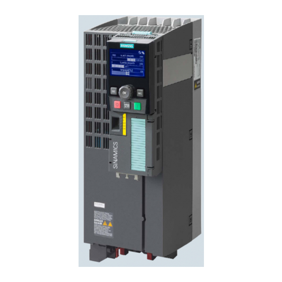
The technical specifications and information about connection conditions are indicated on the rating plate and in the operating instructions. Identifying the converter Main components of the inverter Each SINAMICS G120 inverter comprises a Con- trol Unit and a Power Module. • The Control Unit controls and monitors the connected motor. - Page 26 Description 3.1 Identifying the converter Further inverter components The following components are available so that you can adapt the inverter to different applications and ambient conditions: ● Line filter (Page 33) ● Line reactor (Page 34) ● Output reactor (Page 37) ●...
-
Page 27: Control Units
6SL3243-0BB30-1FA0 PROFINET IO, EtherNet/IP CU230P-2 CAN 6SL3243-0BB30-1CA3 CANopen CU230P-2 BT 6SL3243-6BB30-1HA3 USS, Modbus RTU, BACnet MS/TP, P1 Exclusive version for Siemens IC BT Memory cards Table 3- 1 Memory cards to back up inverter settings Scope of delivery Article number... -
Page 28: Power Module
Description 3.3 Power Module Power Module Important data on the Power Modules is provided in this section. Further information is contained in the hardware installation manuals listed in Section Manuals for your inverter (Page 451). All power data refers to rated values or to power for operation with low overload (LO). Which Power Module can I use with the Control Unit? You can operate the CU230P-2 Control Unit with the following Power Modules: •... - Page 29 Description 3.3 Power Module Figure 3-2 Power Modules with the push-through system FSA … FSC PM230, 3 AC 400 V - pump and fan applications The PM230 Power Module is available without a filter or with integrated class A line filter. Article number range: 6SL3210-1NE…...
- Page 30 Description 3.3 Power Module PM240-2 - for standard applications The PM240-2 Power Module is available without a filter or with an integrated class A line filter. The PM240-2 permits dynamic braking via an external braking resistor. 1 AC / 3 AC 200 V Article number range: 6SL3210-1PB…, 6SL3210-1PC…...
-
Page 31: Power Module In Ip55 Degree Of Protection / Ul Type 12
Description 3.3 Power Module PM250, 3 AC 400 V - Applications with energy recovery The PM250 Power Module is available without a filter or with an integrated class A line filter with degree of protection IP20. The PM250 permits dynamic braking with energy recovery into the line supply. -
Page 32: Components For The Power Modules
Description 3.4 Components for the Power Modules Components for the Power Modules 3.4.1 Accessories for installation and shielding Shield connection kit Establish the shield and strain relief for the power con- nections using the shield connection kit. The shield connection kit comprises a shield plate and serrated strips with screws. -
Page 33: Line Filter
Description 3.4 Components for the Power Modules 3.4.2 Line filter With a line filter, the inverter can achieve a higher radio interference class. An ex- ternal filter is not required for inverters with integrated line filter. Adjacent examples of line filters. The line filter corresponds to Class A or B according to EN55011: 2009. -
Page 34: Line Reactor
Description 3.4 Components for the Power Modules External line filters for PM250 Power Module Power Line filter, class B 6SL3225-0BE25-5AA0, 7.5 kW … 15.0 kW 6SL3203-0BD23-8SA0 6SL3225-0BE27-5AA0, 6SL3225-0BE31-1AA0 External line filters for PM330 Power Module Power Line filter according to EN 61800-3 Category C2 6SL3310-1PE33-0AA0, 160 kW …... - Page 35 Description 3.4 Components for the Power Modules Line reactors for PM240 Power Module Power Line reactor 6SL3224-0BE13-7UA0, 0.37 kW … 0.55 kW 6SE6400-3CC00-2AD3 6SL3224-0BE15-5UA0 6SL3224-0BE17-5UA0, 0.75 kW … 1.1 kW 6SE6400-3CC00-4AD3 6SL3224-0BE21-1UA0 6SL3224-0BE21-5UA0 1.5 kW 6SE6400-3CC00-6AD3 6SL3224-0BE22-2☐A0, 2.2 kW … 3.0 kW 6SL3203-0CD21-0AA0 6SL3224-0BE23-0☐A0 6SL3224-0BE24-0☐A0...
- Page 36 Description 3.4 Components for the Power Modules Line reactors for PM240-2, 400 V Power Module Power Line reactor 6SL3210-1PE11-8☐L1, 0.55 kW … 1.1 kW 6SL3203-0CE13-2AA0 6SL3210-1PE12-3☐L1, 6SL3210-1PE13-2☐L1 6SL3210-1PE14-3☐L1, 1.5 kW … 3 kW 6SL3203-0CE21-0AA0 6SL321☐-1PE16-1☐L1, 6SL321☐-1PE18-0☐L1 6SL3210-1PE21-1☐L0, 4 kW … 7.5 kW 6SL3203-0CE21-8AA0 6SL3210-1PE21-4☐L0, 6SL321☐-1PE21-8☐L0...
-
Page 37: Output Reactor
Description 3.4 Components for the Power Modules 3.4.4 Output reactor Output reactors reduce the voltage stress on the motor windings and the load placed on the inverter as a result of capacitive recharging currents in the cables. An output reactor is required for shielded motor cables longer than 50 m or unshielded motor cables longer than 100 m. - Page 38 Description 3.4 Components for the Power Modules Power Module Power Output reactor 6SL3210-1NE26-0☐L0 30 kW 6SE6400-3TC05-4DD0 6SL3210-1NE27-5☐L0 37 kW 6SE6400-3TC08-0ED0 6SL3210-1NE28-8☐L0 45 kW 6SE6400-3TC07-5ED0 6SL3210-1NE31-1☐L0 55 kW 6SE6400-3TC14-5FD0 6SL3210-1NE31-5☐L0 75 kW 6SE6400-3TC15-4FD0 Output reactors for PM230 push-through Power Modules Power Module Power Output reactor 6SL3211-1NE17-7☐L0...
- Page 39 Description 3.4 Components for the Power Modules Output reactors for PM240 Power Module Power Module Power Output reactor 6SL3224-0BE13-7UA0, 0.37 kW … 1.5 kW 6SE6400-3TC00-4AD2 6SL3224-0BE15-5UA0, 6SL3224-0BE17-5UA0, 6SL3224-0BE21-1UA0, 6SL3224-0BE21-5UA0 6SL3224-0BE22-2☐A0, 2.2 kW … 4.0 kW 6SL3202-0AE21-0CA0 6SL3224-0BE23-0☐A0, 6SL3224-0BE24-0☐A0 6SL3224-0BE25-5☐A0, 7.5 kW … 15.0 kW 6SL3202-0AJ23-2CA0 6SL3224-0BE27-5☐A0, 6SL3224-0BE31-1☐A0...
- Page 40 Description 3.4 Components for the Power Modules Output reactors for PM240-2 Power Modules, 200 V Power Module Power Output reactor 6SL3210-1PB13-0☐L0, 0.55 kW … 0.75 kW 6SL3202-0AE16-1CA0 6SL321☐-1PB13-8☐L0 6SL3210-1PB15-5☐L0 1.1 kW 6SL3210-1PB17-4☐L0 1.5 kW 6SL3202-0AE18-8CA0 6SL321☐-1PB21-0☐L0 2.2 kW 6SL3202-0AE21-8CA0 6SL3210-1PB21-4☐L0, 3 kW …...
-
Page 41: Sine-Wave Filter
Description 3.4 Components for the Power Modules 3.4.5 Sine-wave filter The sine-wave filter at the inverter output limits the voltage rate-of-rise and the peak voltages at the motor winding. The maximum permissible length of motor feeder cables is increased to 300 m. The following applies when using a sine-wave filter: •... -
Page 42: Dv/Dt Filter
Description 3.4 Components for the Power Modules Sine-wave filter for PM250 Power Module Power Module Power Sine-wave filter 6SL3225-0BE25-5☐A0 7.5 kW 6SL3202-0AE22-0SA0 6SL3225-0BE27-5☐ A0, 11.0 kW … 15.0 kW 6SL3202-0AE23-3SA0 6SL3225-0BE31-1☐A0 6SL3225-0BE31-5☐A0, 18.5 kW … 22 kW 6SL3202-0AE24-6SA0 6SL3225-0BE31-8☐A0 6SL3225-0BE32-2☐A0 30 kW 6SL3202-0AE26-2SA0 6SL3225-0BE33-0☐A0,... - Page 43 Description 3.4 Components for the Power Modules Braking resistors for PM240 Power Modules Power Braking Mod- Braking resistor 6SL3224-0BE13-7UA0, 0.37 kW … 1.5 kW 6SE6400-4BD11-0AA0 6SL3224-0BE15-5UA0, 6SL3224-0BE17-5UA0, 6SL3224-0BE21-1UA0, 6SL3224-0BE21-5UA0 6SL3224-0BE22-2☐A0, 2.2 kW … 4.0 kW 6SL3201-0BE12-0AA0 6SL3224-0BE23-0☐A0, 6SL3224-0BE24-0☐A0 6SL3224-0BE25-5☐A0, 7.5 kW … 15.0 kW 6SE6400-4BD16-5CA0 6SL3224-0BE27-5☐A0 6SL3224-0BE31-1☐A0...
- Page 44 Description 3.4 Components for the Power Modules Braking resistors for PM240-2, 400 V Power Module Power Braking resistor 6SL3210-1PE11-8❒L1, 0.55 kW … 1.5 kW 6SL3201-0BE14-3AA0 6SL3210-1PE12-3❒L1, 6SL3210-1PE13-2❒L1, 6SL3210-1PE14-3❒L1 6SL321❒-1PE16-1❒L1, 2.2 kW … 3.0 kW 6SL3201-0BE21-0AA0 6SL321❒-1PE18-0❒L1 6SL3210-1PE21-1❒L0, 4 kW … 7.5 kW 6SL3201-0BE21-8AA0 6SL3210-1PE21-4❒L0, 6SL321❒-1PE21-8❒L0...
-
Page 45: Motor Series That Are Supported
1PH8 induction motors motors Multi-motor drives are permissible, i.e. multiple motors operated on one inverter. See also: Multi- motor drive (http://support.automation.siemens.com/WW/view/ en/84049346). SIMOTICS FD IEC motors SIMOTICS GP, SIMOTICS SD reluctance mo- tors 1LM1, 1LQ1, 1LL1 squirrel cage induction motors 1FP1 reluctance motors for inverter operation. -
Page 46: Tools To Commission The Converter
If you are using your own connection cable, carefully note the maximum permissible length of 5 m. PC tools STARTER STARTER on DVD: 6SL3072-0AA00-0AG0 System requirements and download: STARTER (http://support.automation.siemens.com/WW/view/en/2623320 Help regarding operation: STARTER videos (http://www.automation.siemens.com/mcms/mc-drives/en/low- voltage-inverter/sinamics-g120/videos/Pages/videos.aspx) Startdrive Startdrive on DVD: 6SL3072-4CA02-1XG0 System requirements and download: Startdrive (http://support.automation.siemens.com/WW/view/en/6803456... -
Page 47: Installing
Installing Overview of the inverter installation Installing the inverter Precondition Before installation, please check: ● Are the required inverter components available? – Power Module – Control Unit – Accessories, e.g. line reactor or braking resistor ● Do you have the necessary tools and small parts/components required to install the inverter? Procedure To install the inverter, proceed as follows:... -
Page 48: Connecting Inverters In Compliance With Emc
Installing 4.2 Connecting inverters in compliance with EMC Connecting inverters in compliance with EMC 4.2.1 EMC-compliant connection of the converter EMC-compliant installation of the inverter and motor are required in order to ensure disturbance-free operation of the drive. Install and operate inverters with IP20 degree of protection in a closed control cabinet. Inverters with degree of protection IP55 are suitable for installation outside a control cabinet. - Page 49 Installing 4.2 Connecting inverters in compliance with EMC ● For screw connections onto painted or anodized surfaces, establish a good conductive contact using one of the following methods: – Use special (serrated) contact washers that cut through the painted or anodized surface.
- Page 50 Further information You can find additional information about the EMC installation guidelines on the Internet: EMC installation guideline (http://support.automation.siemens.com/WW/view/en/60612658). Converter with CU230P-2 Control Units Operating Instructions, 04/2015, FW V4.7 SP3, A5E34257946B AB...
-
Page 51: Amount The Shield Plate Onto The Power Module
Installing 4.2 Connecting inverters in compliance with EMC 4.2.3 Amount the shield plate onto the Power Module Shielding with shield plate: Connect the cable shields to the shield plate through the largest possible surface area using shield clamps. Depending on the particular Power Module, the shield plate is included in the scope of delivery, or is optionally available as shield connection kit. - Page 52 Installing 4.2 Connecting inverters in compliance with EMC Example of EMC-compliant wiring with a PM240 Power Module The terminal cover is not shown in the diagram, so that it is easier to see how the cable is connected. ① Line connection cable (unshielded) for Power Modules with integrated line filter. If you use an external line filter, you will need a shielded cable between the line filter and the Power Module.
- Page 53 Installing 4.2 Connecting inverters in compliance with EMC Figure 4-4 Shield connection - detail EMC-compliant wiring of Power Modules in degree of protection IP55 / UL type 12 The following diagram shows the EMC-compliant installation of Power Modules with degree of protection IP55 / UL type 12.
-
Page 54: Installing Reactors, Filters And Braking Resistors
Installing 4.3 Installing reactors, filters and braking resistors Installing reactors, filters and braking resistors Installing reactors, filters and braking resistors The following supplementary components may be required depending on the Power Modules and the particular application: ● Line reactors ● Filter ●... - Page 55 Installing 4.3 Installing reactors, filters and braking resistors Installing two base components You can combine up to two base components. The permissible combination depends on the particular base components and the inverter frame size. Figure 4-7 Permissible combinations of two base components Converter with CU230P-2 Control Units Operating Instructions, 04/2015, FW V4.7 SP3, A5E34257946B AB...
-
Page 56: Installing Power Modules
Installing 4.4 Installing Power Modules Installing Power Modules Installing Power Modules The following is required to correctly install a Power Module: ● Install the Power Module in a control cabinet. ● Install the Power Modules vertically with the line and motor connections facing downwards. - Page 57 Installing 4.4 Installing Power Modules Procedure Proceed as follows to correctly install the Power Module: 1. Prepare the cutout and the mounting holes for the Power Module and the mounting frame corresponding to the dimension drawings of the mounting frame. Also note that the PT Power Modules must be vertically mounted with the line and motor connections facing downwards.
-
Page 58: Dimensions, Hole Drilling Templates, Minimum Clearances, Tightening Torques
Installing 4.4 Installing Power Modules 4.4.1 Dimensions, hole drilling templates, minimum clearances, tightening torques Dimensions and drilling patterns for the PM230 Power Modules, IP55 Table 4- 1 Dimensions Frame size Dimensions (mm) Drilling dimensions (width) (height) (depth) 17.5 17.5 17.5 Depth with - BOP-2/blanking cover + 7 mm;... - Page 59 Installing 4.4 Installing Power Modules Dimensions and drilling patterns for Power Modules with IP20 degree of protection Defining the dimensions: Drilling patterns for the PM230 and PM240-2 Power Modules: FSB … FSF Drilling patterns for the PM240, PM250, and PM260 Power Modules: FSB…FSF Converter with CU230P-2 Control Units Operating Instructions, 04/2015, FW V4.7 SP3, A5E34257946B AB...
- Page 60 Installing 4.4 Installing Power Modules Dimensions and drilling patterns for the PM330 Power Modules: Table 4- 3 Dimensions of the PM230, without/with integrated filter Frame size Dimensions (mm) Drilling dimensions (width) (height) (depth) 62,3 419/512 325/419 499/635 405/451 634/934 598/899 with shield connection kit: FSA: + 80 mm;...
- Page 61 Installing 4.4 Installing Power Modules Table 4- 5 Dimensions for PM330 Frame size a (width) b (height) c (depth) 452 mm 1402 mm 328 mm 45 mm 548 mm 1660 mm 393 mm 37 mm Table 4- 6 Mounting hardware and clearances to other devices for PM330 Frame size Stock Tightening torque...
- Page 62 Installing 4.4 Installing Power Modules Table 4- 8 Mounting hardware and clearances to other devices for PM240 Frame size Hardware Tightening torque (Nm) Clearances (mm) Bottom Lateral M4 screws M4 screws M5 screws FSD, FSE M6 screws M8 screws M8 screws Can be mounted without any lateral clearance for ambient temperatures of up to 40 °C in opera- tion.
- Page 63 Installing 4.4 Installing Power Modules Table 4- 11 Dimensions for PM250, with/without integrated filter Frame size Dimensions (mm) Drilling dimensions (width) (height) (depth) 419/512 325/419 499/635 405/541 634/934 598/899 With shield connection kit: FSC: + 77 mm; FSD…FSF: + 123 mm Total depth of the inverter: See below.
- Page 64 Installing 4.4 Installing Power Modules Dimensions and drilling patterns for Power Modules with through-hole technology Mounting cutout in the control cabinet for the PM230 and PM240- 2 Power Modules; Holes for fastening the mounting frame FSA, FSB Table 4- 15 Dimensions for PM230 in push-through technology Frame Dimensions (mm)
- Page 65 Installing 4.4 Installing Power Modules Table 4- 17 Dimensions for PM240-2 in push-through technology Frame Dimensions (mm) Drilling dimensions (mm) Cabinet cutout size (mm) (width) (height) (depth) 147.5 34.5 30.5 With shield connection kit: FSA: +84 mm; FSB: +85 mm; FSC: +89 mm Total depth of the inverter: See below.
-
Page 66: Digital Inputs And Outputs On The Pm330 Power Module
Installing 4.4 Installing Power Modules Total depth of the inverter Power Modules frame sizes FSA … FSF ① ② As a minimum, the inverter comprises a Power Module and an inserted Control Unit: Overall depth of the inverter = depth of the Power Module + 60 mm (Control Unit) ①... - Page 67 Installing 4.4 Installing Power Modules Terminal Name Meaning Technical data put/output External power supply Input 24 V DC (20.1 ... 28.8 V) Current consumption: max. 2 A Electronics ground Refer- ence External alert External alarm Input Voltage: -3 V ... +30 V Current drain: External fault External fault...
- Page 68 Installing 4.4 Installing Power Modules Note Inputs are low active. All signal inputs are low active (wire-break-proof). Note If terminals 3 ... 6 are not used, then you must connect 24 V DC to these. To do this, use an external power supply or terminal 9 on the Control Unit. The reference potential is connected to terminal X9:2, 7 and terminal 28 on the Control Unit.
-
Page 69: Connecting The Line Supply, Motor And Converter Components
Installing 4.5 Connecting the line supply, motor and converter components Connecting the line supply, motor and converter components 4.5.1 Permissible line supplies Note Restrictions for installation altitudes above 2000 m Above an installation altitude of 2000 m, the permissible line supplies are restricted. See also: Restrictions for special ambient conditions (Page 428). - Page 70 Installing 4.5 Connecting the line supply, motor and converter components TN line system A TN line system transfers the PE protective conductor to the installed plant or system using a cable. Generally, in a TN line system the neutral point is grounded. There are versions of a TN line supply with a grounded line the conductor, e.g.
- Page 71 Installing 4.5 Connecting the line supply, motor and converter components TT line system In a TT line system, the transformer grounding and the installation grounding are independent of one another. There are TT line supplies where the neutral conductor N is either transferred – or not. Inverter operated on a TT line system ●...
- Page 72 When connected to an IT line supply, you must open the connection to the basic interference suppression board of the Power Module. You can find additional information on the Internet: Hardware installation manual for PM330 Power Modules (https://support.industry.siemens.com/cs/ww/en/view/90580072/64282054155). Converter with CU230P-2 Control Units Operating Instructions, 04/2015, FW V4.7 SP3, A5E34257946B AB...
-
Page 73: Connecting The Inverter
Installing 4.5 Connecting the line supply, motor and converter components 4.5.2 Connecting the inverter Figure 4-11 Connecting the PM230 IP20 and push-through Power Module Figure 4-12 Connecting the PM230 IP55 Power Module Figure 4-13 Connecting the PM240, PM240-2 IP20 and push-through Power Modules Converter with CU230P-2 Control Units Operating Instructions, 04/2015, FW V4.7 SP3, A5E34257946B AB... - Page 74 Installing 4.5 Connecting the line supply, motor and converter components PM240 and PM240-2 Power Modules are available with and without integrated Class A line filters. For higher EMC requirements you need an external Class B line filter. Figure 4-14 Connecting the PM250 Power Module Figure 4-15 Connecting the PM260 Power Module Figure 4-16...
- Page 75 Installing 4.5 Connecting the line supply, motor and converter components DANGER Danger to life as a result of a hazardous voltage at the motor connections As soon as the inverter is connected to the line supply, the motor connections of the inverter may carry dangerous voltages.
- Page 76 Before you connect the motor, ensure that the motor has the appropriate connection for your application: Motor is connected in the star or delta configuration With SIEMENS motors, you will see a diagram of both connection methods on the inside of the cover of the terminal box: •...
-
Page 77: Connecting A Braking Resistor
Installing 4.5 Connecting the line supply, motor and converter components 4.5.3 Connecting a braking resistor WARNING Danger to life due to fire spreading because of an unsuitable or improperly installed braking resistor Fire and smoke development can cause severe personal injury or material damage. Using an unsuitable braking resistor can cause fires and smoke to develop. - Page 78 ● Connect the external braking resistor at terminals G and H of the Braking Module. You can find additional information on the Internet: Hardware installation manual for PM330 Power Modules (https://support.industry.siemens.com/cs/ww/en/view/90580072/64282054155). Converter with CU230P-2 Control Units Operating Instructions, 04/2015, FW V4.7 SP3, A5E34257946B AB...
-
Page 79: Installing Control Unit
Installing 4.6 Installing Control Unit Installing Control Unit Plugging the Control Unit onto an IP20 Power Module FSA … FSF Procedure Proceed as follows to plug the Control Unit onto a Power Module: 1. Locate the lugs at the rear of the Control Unit in the matching recesses of the Power Module. - Page 80 Installing 4.6 Installing Control Unit Note Failure of the inverter as a result of the Control Unit overtemperature The Control Unit can overheat when the housing flap is open in operation. To protect itself against damage, the Control Unit switches off the drive when an overtemperature condition occurs.
- Page 81 Installing 4.6 Installing Control Unit Installing a Control Unit in an IP55 Power Module FSD … FSF Procedure Proceed as follows to install a Control Unit in a IP55 Power Module FSD … FSF: 1. Open the Power Module door using the key supplied. 2.
-
Page 82: Overview Of The Interfaces
Installing 4.6 Installing Control Unit 4.6.1 Overview of the interfaces Interfaces at the front of the Control Unit To access the interfaces at the front of the Control Unit, you must lift the Operator Panel (if one is being used) and open the front doors. ①... -
Page 83: Fieldbus Interface Allocation
Installing 4.6 Installing Control Unit 4.6.2 Fieldbus interface allocation Interfaces at the lower side of the CU230P-2 Control Unit Converter with CU230P-2 Control Units Operating Instructions, 04/2015, FW V4.7 SP3, A5E34257946B AB... -
Page 84: Terminal Strips
Installing 4.6 Installing Control Unit 4.6.3 Terminal strips Terminal strips with wiring example The following applies to systems compliant with UL: Maximum current, 3 A 30 V DC or 2 A 250 V AC All terminals labelled with reference potential "GND" are connected internally in the inverter. Reference potential "DI COM"... - Page 85 Installing 4.6 Installing Control Unit Additional options for wiring the digital inputs You must remove the jumper be- tween terminals 28 and 69 if it is necessary to have electrical isolation between the external power supply and the internal inverter power sup- ply.
-
Page 86: Factory Setting Of The Interfaces
Installing 4.6 Installing Control Unit 4.6.4 Factory setting of the interfaces Factory interface settings The factory setting of the interfaces depends on the Control Unit. Control Units with USS or CANopen interface The fieldbus interface is not active. --- No function. DO x: p073x AO 0: p0771[0] DI x: r0722.x... - Page 87 Installing 4.6 Installing Control Unit --- No function. DO x: p073x AO 0: p0771[0] DI x: r0722.x Speed setpoint (main setpoint): p1070[0] = 2050[1] Figure 4-20 Factory setting of the CU230P-2 DP and CU230P-2 PN Control Units Converter with CU230P-2 Control Units Operating Instructions, 04/2015, FW V4.7 SP3, A5E34257946B AB...
-
Page 88: Default Setting Of The Interfaces
Installing 4.6 Installing Control Unit Changing the function of the terminals The function of the terminals marked in color in the two diagrams above, can be set. In order not to have to successively change terminal for terminal, several terminals can be jointly set using default settings ("p0015 Macro drive unit"). - Page 89 Installing 4.6 Installing Control Unit Default setting 9: "Standard I/O with MOP" DO 0: p0730, DO 1: p0731 AO 0: p0771[0], AO 1: p0771[1] DI 0: r0722.0, …, DI 3: r0722.3 Motorized potentiometer, setpoint after the ramp-function generator: r1050 Speed setpoint (main setpoint): p1070[0] = 1050 Designation in BOP-2: Std MoP Default setting 12: "Standard I/O with analog setpoint"...
- Page 90 Installing 4.6 Installing Control Unit Default setting 14: "Process industry with fieldbus" DO 0: p0730, DO 1: p0731 AO 0: p0771[0], AO 1: p0771[1] DI 0: r0722.0, …, DI 5: r0722.5 Motorized potentiometer, setpoint after the ramp-function generator: r1050 Speed setpoint (main setpoint): p1070[0] = 2050[1], p1070[1] = 1050 Designation in BOP-2: Proc Fb Converter with CU230P-2 Control Units Operating Instructions, 04/2015, FW V4.7 SP3, A5E34257946B AB...
- Page 91 Installing 4.6 Installing Control Unit Default setting 15: "Process industry" DO 0: p0730, DO 1: AO 0: p0771[0], AO 1: DI 0: r0722.0, …, DI 5: AI 0: r0755[0] p0731 p0771[1] r0722.5 Motorized potentiometer, setpoint after the ramp-function generator: r1050 Speed setpoint (main setpoint): p1070[0] = 755[0], p1070[1] = 1050 Designation in BOP-2: Proc Default setting 17: "2-wire (forward/backward 1)"...
- Page 92 Installing 4.6 Installing Control Unit Default setting 18: "2-wire (forward/backward 2)" DO 0: p0730, DO 1: AO 0: p0771[0], AO 1: DI 0: r0722.0, …, DI 2: AI 0: r0755[0] p0731 p0771[1] r0722.2 Speed setpoint (main setpoint): p1070[0] = 755[0] Designation in BOP-2: 2-wIrE 2 Default setting 19: "3-wire (enable/forward/backward)"...
- Page 93 Installing 4.6 Installing Control Unit Default setting 20: "3-wire (enable/on/reverse)" DO 0: p0730, DO 1: AO 0: p0771[0], AO 1: DI 0: r0722.0, …, DI 4: AI 0: r0755[0] p0731 p0771[1] r0722.4 Speed setpoint (main setpoint): p1070[0] = 755[0] Designation in BOP-2: 3-wIrE 2 Default setting 21: "USS fieldbus"...
- Page 94 Installing 4.6 Installing Control Unit Default setting 22: "CAN fieldbus" DO 0: p0730, DO 1: p0731 AO 0: p0771[0], AO 1: p0771[1] DI 2: r0722.2 Speed setpoint (main setpoint): p1070[0] = 2050[1] Designation in BOP-2: FB CAN Converter with CU230P-2 Control Units Operating Instructions, 04/2015, FW V4.7 SP3, A5E34257946B AB...
- Page 95 Installing 4.6 Installing Control Unit Default setting 101: "Universal application" DO 0: p0730, …, DO 2: AO 0: p0771[0], AO 1: DI 0: r0722.0, …, DI 5: AI 0: r0755[0] p0732 p0771[1] r0722.5 Additional settings: Fixed speed setpoint 1: p1001 = 800 rpm •...
- Page 96 Installing 4.6 Installing Control Unit Default setting 103: "Pump pressure control" DO 0: p0730, …, DO 2: AO 0: p0771[0], AO 1: DI 0: r0722.0 AI 0: r0755[0] p0732 p0771[1] Additional settings: Differential pressure control using the technology controller • Technological unit: p0595 = 1 (%), reference variable: p0596 = 1 •...
- Page 97 Installing 4.6 Installing Control Unit Default setting 104: "ESM stairwell pressure control" DO 0: p0730, …, DO 2: AO 0: p0771[0], AO 1: DI 0: r0722.0 AI 0: r0755[0] p0732 p0771[1] Additional settings: Pressure control using the technology controller • Analog inputs smoothing time constant: p0753 = 500 ms •...
- Page 98 Installing 4.6 Installing Control Unit Default setting 105: "Fan pressure control + ESM with fixed setpoint" DO 0: p0730, …, DO 2: AO 0: p0771[0], AO 1: DI 0: r0722.0, DI 1: AI 0: r0755[0] p0732 p0771[1] r0722.1 Additional settings: Pressure control using the technology controller •...
- Page 99 Installing 4.6 Installing Control Unit Default setting 106: "Cooling tower with active sensor + hibernation" DO 0: p0730, …, DO 2: AO 0: p0771[0], AO 1: DI 0: r0722.0 AI 0: r0755[0] p0732 p0771[1] Additional settings: Temperature control using the technology controller •...
- Page 100 Installing 4.6 Installing Control Unit Default setting 107: "Cooling tower with LG-Ni1000 sensor + hibernation" DO 0: p0730, …, DO 2: AO 0: p0771[0], AO 1: DI 0: r0722.0 AI 3: r0755[3] p0732 p0771[1] Additional settings: Temperature control using the technology controller •...
- Page 101 Installing 4.6 Installing Control Unit Default setting 108: "USS fieldbus" DO 0: p0730, …, DO 2: p0732 AO 0: p0771[0], AO 1: p0771[1] DI 2: r0722.2 Designation in BOP-2: P_F USS Default setting 109: "Modbus RTU field" DO 0: p0730, …, DO 2: p0732 AO 0: p0771[0], AO 1: p0771[1] DI 2: r0722.2 Designation in BOP-2: P_F Mod...
- Page 102 Installing 4.6 Installing Control Unit Default setting 110: "BACnet MS/TP fieldbus" DO 0: p0730, …, DO 2: p0732 AO 0: p0771[0], AO 1: p0771[1] DI 2: r0722.2 Designation in BOP-2: P_F bAc Default setting 111: "Fixed setpoints" DO 0: p0730, …, DO 2: p0732 AO 0: p0771[0], AO 1: p0771[1] DI 0: r0722.0, …, DI 3: r0722.3 Additional settings:...
- Page 103 Installing 4.6 Installing Control Unit Default setting 112: "CO2 sensor, 2 PID setpoints" DO 0: p0730, …, DO 2: AO 0: p0771[0], AO 1: DI 0: r0722.0, DI 2: AI 0: r0755[0] p0732 p0771[1] r0722.2 Additional settings: control using the technology controller •...
- Page 104 Installing 4.6 Installing Control Unit Default setting 113: "Temperature-dependent pressure setpoint" DO 0: p0730, …, DO 2: AO 0: p0771[0], AO 1: DI 0: r0722.0 AI 0: r0755[0], AI 2: p0732 p0771[1] r0755[2] Additional settings: Temperature control using the technology controller •...
- Page 105 Installing 4.6 Installing Control Unit Default setting 114: "P1 fieldbus" DO 0: p0730, …, DO 2: p0732 AO 0: p0771[0], AO 1: p0771[1] DI 2: r0722.2 Designation in BOP-2: p_f_P1 Default setting 120: "PID settings for pumps and fans" The default setting restores the function of the terminal strip to the factory setting. Technology controller setting: •...
-
Page 106: Wiring Terminal Strips
Installing 4.6 Installing Control Unit 4.6.6 Wiring terminal strips WARNING Danger to life as a result of hazardous voltages when connecting an unsuitable power supply Death or serious injury can result when live parts are touched in the event of a fault. •... -
Page 107: Connecting The Inverter To The Fieldbus
See also:EMC installation guideline (http://support.automation.siemens.com/WW/view/en/60612658) ● Use the shield connection plate of the Control Unit to connect the shield and as strain relief, see also: Control Units (Page 27). -
Page 108: Profinet
Installing 4.6 Installing Control Unit 4.6.7.1 PROFINET You can either communicate via Ethernet using the inverter, or integrate the inverter in a PROFINET network. ● The inverter as an Ethernet station (Page 451) ● PROFINET IO operation (Page 109) In PROFINET IO operation, the inverter supports the following functions: –... - Page 109 – The configuration of the functions is described in the PROFINET system description (http://support.automation.siemens.com/WW/view/en/19292127) manual. This manual describes the control of the inverter using primary control. How to access the inverter as an Ethernet station is described in the Fieldbus function manual (Page 451) in the section "The inverter as an Ethernet station".
- Page 110 Additional information on this topic is provided in the "Fieldbuses" Function Manual, also see Manuals for your inverter (Page 451). Configuring the communication using a non-Siemens control 1. Import the device file (GSDML) of the inverter into the engineering tool for your control system.
- Page 111 Set p0804 = 12. The inverter writes the GSDML as zipped file (*.zip) into directory /SIEMENS/SINAMICS/DATA/CFG on the memory card. 2. Unzip the GSDML file to a folder on your computer. 3. Import the GSDML into the configuring tool of your control system.
-
Page 112: Profibus
● Diagnostic alarms General information on PROFIBUS DP can be found on the Internet at the following links: ● Information about PROFIBUS DP (http://www.automation.siemens.com/net/html_76/support/printkatalog.htm). ● PROFIBUS user organization (http://www.profibus.com/downloads/installation-guide/). What do you need for communication via PROFIBUS? Check the communication settings using the following table. If you answer "Yes" to the questions, you have correctly set the communication settings and can control the inverter via the fieldbus. - Page 113 ● If the inverter is not listed in the hardware library, you can either install the newest STARTER version or install the GSD of the inverter through "Extras/GSD-Install file" in HW-Config. See also GSD (http://support.automation.siemens.com/WW/view/en/22339653/133100). When you have installed the GSD, configure the communication in the SIMATIC control. Setting the address...
- Page 114 Installing 4.6 Installing Control Unit Procedure To change the bus address, proceed as follows: 1. Set the address using one of the subsequently listed options: – using the address switch – from an operator panel using parameter p0918 – in STARTER using screen form "Control Unit/Communication/PROFIBUS" – or using the expert list in parameter p0918 After you have changed the address in STARTER, carry out RAM to ROM ( 2.
-
Page 115: Commissioning
Commissioning Commissioning guidelines Overview 1. Define the requirements of your application placed on the drive. → (Page 116) . 2. Reset the inverter when required to the factory setting. → (Page 148) . 3. Check whether the factory setting of the inverter is already sufficient for your application. -
Page 116: Preparing For Commissioning
Commissioning 5.2 Preparing for commissioning Preparing for commissioning 5.2.1 Collecting motor data Before starting commissioning, you must know the following data: ● Which motor is connected to the inverter? Note down the Article No. of the motor and the motor’s nameplate data. If available, note down the motor code on the motor’s nameplate. - Page 117 Commissioning 5.2 Preparing for commissioning Switching the motor on and off The inverter is set in the factory as follows: ● After the ON command, the motor accelerates within the ramp-up time (referred to 1500 rpm) to its speed setpoint. ●...
-
Page 118: Defining Additional Requirements For The Application
Commissioning 5.2 Preparing for commissioning Operate the motor in the factory setting For basic applications, you can try to operate the drive with a rated power < 18.5 kW without any other commissioning steps. Check whether the control quality of the drive without commissioning is adequate for the requirements of the application. -
Page 119: Commissioning Using A Bop-2 Operator Panel
Commissioning 5.3 Commissioning using a BOP-2 operator panel Commissioning using a BOP-2 operator panel Plugging on an operator panel Procedure To plug an Operator Panel on the Control Unit, proceed as follows: 1. Locate the lower edge of the Operator Panel into the matching recess of the Control Unit. - Page 120 Commissioning 5.3 Commissioning using a BOP-2 operator panel Procedure Proceed as follows to carry out basic commissioning: Press the ESC key. Press one of the arrow keys until the BOP-2 displays the "SETUP" menu. In the "SETUP" menu, press the OK key to start basic commissioning. If you wish to restore all of the parameters to the factory setting before the basic commissioning: 4.1.
- Page 121 Commissioning 5.3 Commissioning using a BOP-2 operator panel 8. Enter the motor data: 8.1. Motor type Depending on the particular inverter, it is possible that the BOP-2 does not list all of the following motor types. INDUCT Third-party induction motor SYNC Third-party synchronous motor RELUCT...
- Page 122 Commissioning 5.3 Commissioning using a BOP-2 operator panel 9. Application and control mode 9.1. Select the application: VEC STD In all applications, which do not fit the other setting options. PUMP FAN Applications involving pumps and fans SLVC 0HZ Applications with short ramp-up and ramp- down times.
- Page 123 Commissioning 5.3 Commissioning using a BOP-2 operator panel Selecting the suitable control mode Control mode U/f control or flux current control (FCC) Vector control Motors that can be Induction motors Induction, synchronous and reluctance motors operated Power Modules No restrictions that can be oper- ated Application exam-...
- Page 124 Commissioning 5.3 Commissioning using a BOP-2 operator panel Select the default setting for the interfaces of the inverter that is suita- ble for your application. You will find the available default settings in Section: Default setting of the interfaces (Page 88) Minimum and maximum motor speed Scaling of analog input 0 Motor ramp-up time...
- Page 125 Commissioning 5.3 Commissioning using a BOP-2 operator panel Identifying the motor data and optimizing the closed-loop control The inverter has several techniques to automatically identify the motor data and optimize the speed control. To start the motor data identification routine, you must switch-on the motor via the terminal strip, fieldbus or from the operator panel.
- Page 126 Commissioning 5.3 Commissioning using a BOP-2 operator panel Procedure when using the BOP-2 operator panel To start the motor data identification, proceed as follows: ⇒ Press the HAND/AUTO key. The BOP-2 displays the symbol for manual operation. Switch on the motor. The motor data identification takes several seconds.
-
Page 127: Basic Commissioning With Application Classes
Commissioning 5.3 Commissioning using a BOP-2 operator panel 5.3.2 Basic commissioning with application classes 5.3.2.1 Starting basic commissioning Carry out basic commissioning Preconditions • The power supply is switched on. • The operator panel displays setpoints and actual values. Procedure Proceed as follows to carry out basic commissioning: Press the ESC key. - Page 128 Commissioning 5.3 Commissioning using a BOP-2 operator panel Select a suitable application class When selecting an application class, the inverter appropriately sets the closed-motor control. Application class Standard Drive Control Dynamic Drive Control Motors that can be Induction motors Induction, synchronous and reluctance motors operated Power Modules PM240, PM240-2...
-
Page 129: Standard Drive Control
Commissioning 5.3 Commissioning using a BOP-2 operator panel 5.3.2.2 Standard Drive Control Motor standard KW 50HZ HP 60HZ NEMA KW 60HZ IEC 60 Hz Supply voltage for the inverter 8. Enter the motor data: 8.1. Motor type Depending on the particular inverter, it is possible that the BOP-2 does not list all of the following motor types. - Page 130 Commissioning 5.3 Commissioning using a BOP-2 operator panel Select the application: VEC STD Constant load: Typical applications include belt conveyor drives. PUMP FAN Speed-dependent load: Typical applications include pumps and fans. Select the default setting for the interfaces of the inverter that is suita- ble for your application.
-
Page 131: Dynamic Drive Control
Commissioning 5.3 Commissioning using a BOP-2 operator panel 5.3.2.3 Dynamic Drive Control Motor standard KW 50HZ HP 60HZ NEMA KW 60HZ IEC 60 Hz Supply voltage for the inverter 8. Enter the motor data: 8.1. Motor type Depending on the particular inverter, it is possible that the BOP-2 does not list all of the following motor types. - Page 132 Commissioning 5.3 Commissioning using a BOP-2 operator panel Select the application: OP LOOP Recommended setting for standard applications. CL LOOP Recommended setting for applications with short ramp- up and ramp-down times. This setting is not suitable for hoisting gear and cranes/lifting gear. HVY LOAD Recommended setting for applications with a high break loose torque.
- Page 133 Commissioning 5.3 Commissioning using a BOP-2 operator panel Identifying the motor data and optimizing the closed-loop control The inverter has several techniques to automatically identify the motor data and optimize the speed control. To start the motor data identification routine, you must switch-on the motor via the terminal strip, fieldbus or from the operator panel.
- Page 134 Commissioning 5.3 Commissioning using a BOP-2 operator panel Procedure when using the BOP-2 operator panel To start the motor data identification, proceed as follows: ⇒ Press the HAND/AUTO key. The BOP-2 displays the symbol for manual operation. Switch on the motor. The motor data identification takes several seconds.
-
Page 135: Commissioning With A Pc
5.4 Commissioning with a PC Commissioning with a PC PC-based commissioning tools STARTER and Startdrive are PC tools to commission Siemens inverters. The graphic user interface supports you when commissioning your inverter. Most of the inverter functions are available in screen forms. -
Page 136: Creating A Project
Commissioning 5.4 Commissioning with a PC 5.4.1 Creating a project Creating a project Procedure In order to create a new project, proceed as follows: 1. In the menu, select "Project" → "New…". 2. Specify a name of your choice for the project. You have created a new project. - Page 137 Commissioning 5.4 Commissioning with a PC Figure 5-4 "Accessible nodes" in Startdrive 6. When the USB interface is appropriately set, then the "Accessible nodes" screen form shows the inverters that can be accessed. Figure 5-5 Inverters found in STARTER Figure 5-6 Inverters found in Startdrive If you have not correctly set the USB interface, then the following "No additional nodes found"...
- Page 138 Commissioning 5.4 Commissioning with a PC Setting the USB interface in STARTER Procedure Proceed as follows to set the USB interface in STARTER: 1. Set the "Access point" to "DEVICE (STARTER, Scout)" and the "PG/PC interface" to "S7USB". 2. Press the "Update" button. You have set the USB interface.
-
Page 139: Go Online And Start The Configuration Wizards
Commissioning 5.4 Commissioning with a PC 5.4.3 Go online and start the configuration wizards Procedure with STARTER Proceed as follows to start configuration of the inverter: 1. Select your project and go online: 2. In the following screen form, select the inverter with which you wish to go online. - Page 140 Commissioning 5.4 Commissioning with a PC Configuring the drive Procedure To configure the drive, proceed as follows: When selecting an application class, the inverter assigns the motor con- trol with the appropriate default settings: • [1] Standard Drive Control (Page 141) •...
-
Page 141: Standard Drive Control
Commissioning 5.4 Commissioning with a PC Application class Standard Drive Control Dynamic Drive Control Max. output fre- 550 Hz 240 Hz quency Torque control Without torque control Speed control with lower-level torque control Commissioning Contrary to "Dynamic Drive Control", a Fewer parameters when compared to "Configu- •... -
Page 142: Dynamic Drive Control
Commissioning 5.4 Commissioning with a PC 5.4.5 Dynamic Drive Control Procedure for application class [2]: Dynamic Drive Control Select the I/O configuration to preassign the inverter interfaces. The possible configurations are listed in Sections: Factory setting of the interfaces (Page 86) and Default setting of the interfaces (Page 88). Set the applicable motor standard and the inverter supply voltage. -
Page 143: Configuration For Experts
Commissioning 5.4 Commissioning with a PC 5.4.6 Configuration for experts Procedure without application class or for the application class [0]: Expert Select the control mode. Select the I/O configuration to preassign the inverter interfaces. The possible configurations are listed in Sections: Factory setting of the interfaces (Page 86) and Default setting of the interfaces (Page 88). - Page 144 Commissioning 5.4 Commissioning with a PC 9. Set the check mark for "RAM to ROM (save data in the drive)" to save your data in the inverter so that it is not lost when the power fails. Select "Finish". Complete the configuration in STARTER Complete the configuration in Startdrive You have now configured the inverter.
- Page 145 Commissioning 5.4 Commissioning with a PC Selecting the suitable control mode Control mode U/f control or flux current control (FCC) Vector control Motors that can be Induction motors Induction, synchronous and reluctance motors operated Power Modules No restrictions that can be oper- ated Application exam- Pumps, fans, and compressors with flow...
-
Page 146: Identify Motor Data
Commissioning 5.4 Commissioning with a PC 5.4.7 Identify motor data Identify motor data WARNING Danger to life from machine movements while motor data identification is in progress The stationary measurement can turn the motor a number of revolutions. The rotating measurement accelerates the motor up to the rated speed. - Page 147 Commissioning 5.4 Commissioning with a PC 4. Switch on the motor. The inverter starts the motor data identification. This measurement can take several minutes. After the measurement, the inverter switches off the motor. 5. Relinquish the master control after the motor data identification. 6.
-
Page 148: Restoring The Factory Setting
Commissioning 5.5 Restoring the factory setting Restoring the factory setting There are cases where something goes wrong when commissioning a drive system e.g.: ● The line voltage was interrupted during commissioning and you were not able to complete commissioning. ● You got confused during the commissioning and you can no longer understand the individual settings that you made. - Page 149 Commissioning 5.5 Restoring the factory setting 5. Press the "Start" button. 6. Wait until the inverter has been reset to the factory setting. You have reset the inverter to factory settings. Procedure with the BOP-2 operator panel Proceed as follows to reset the inverter to factory settings: 1.
-
Page 151: Advanced Commissioning
Advanced commissioning Overview of the inverter functions Figure 6-1 Overview of inverter functions Converter with CU230P-2 Control Units Operating Instructions, 04/2015, FW V4.7 SP3, A5E34257946B AB... - Page 152 Advanced commissioning 6.1 Overview of the inverter functions Functions relevant to all applications Functions required in special applications only The functions that you require in each application are shown The functions whose parameters you only need to adapt in a dark color in the function overview above. when actually required are shown in white in the function overview above.
-
Page 153: Inverter Control
Advanced commissioning 6.2 Inverter control Inverter control 6.2.1 Switching the motor on and off After switching the supply voltage on, the converter normally goes into the "ready to start" state. In this state, the converter waits for the command to switch-on the motor: •... - Page 154 Advanced commissioning 6.2 Inverter control The abbreviations S1 … S5b to identify the converter states are defined in the PROFIdrive profile. Converter Explanation status In this state, the converter does not respond to the ON command. The converter goes into this state under the following conditions: ON was active when switching on the converter.
-
Page 155: Adapt The Default Setting Of The Terminal Strip
Advanced commissioning 6.2 Inverter control 6.2.2 Adapt the default setting of the terminal strip This chapter describes how you adapt the function of individual digital and analog inputs and outputs of the inverter. When using the PM330 Power Module, the inverter also has terminals on the Control Unit via 4 digital inputs DI and 2 digital outputs DO on the Power Module. -
Page 156: Digital Inputs
Advanced commissioning 6.2 Inverter control 6.2.2.1 Digital inputs Changing the function of a digital input To change the function of a digital in- put, you must interconnect the status parameter of the digital input with a binector input of your choice. See also Section: Interconnecting sig- nals in the converter (Page 447). - Page 157 Advanced commissioning 6.2 Inverter control Advanced settings You can debounce the digital input signal using parameter p0724. For more information, please see the parameter list and the function block diagrams 2220 f of the List Manual. Analog inputs as digital inputs To use an analog input as additional digital input, you must interconnect the corresponding status parameter r0722.11 or r0722.12 with a binector...
-
Page 158: Digital Outputs
Advanced commissioning 6.2 Inverter control 6.2.2.2 Digital outputs Changing the function of a digital output To change the function of a digital output, you must interconnect the digital output with a binector output of your choice. See also Section: Interconnecting signals in the converter (Page 447). -
Page 159: Analog Inputs
Advanced commissioning 6.2 Inverter control Advanced settings You can invert the signal of the digital output using parameter p0748. For more information, please see the parameter list and the function block diagrams 2230 f of the List Manual. 6.2.2.3 Analog inputs Overview Changing the function of an analog input: 1. - Page 160 Advanced commissioning 6.2 Inverter control In addition, you must also set the switch associated with the analog input. You can find the switch on the Control Unit behind the front doors. • The DIP switch for AI0 and AI1 (current / voltage) on the Control Unit behind the lower front door.
- Page 161 Advanced commissioning 6.2 Inverter control Adapting the characteristic You must define your own characteristic if none of the default types match your particular application. Example The inverter should convert a 6 mA … 12 mA signal into the value range -100 % … 100 % via analog input 0.
- Page 162 Advanced commissioning 6.2 Inverter control Defining the function of an analog input - example To enter a supplementary setpoint via analog input AI 0, you must interconnect AI 0 with the signal source for the supple- mentary setpoint: Set p1075 = 755[0]. Advanced settings Signal smoothing When required, you can smooth the signal, which you read-in via an analog input, using...
-
Page 163: Analog Outputs
Advanced commissioning 6.2 Inverter control 6.2.2.4 Analog outputs Overview Changing the function of an analog output: 1. Define the analog output type using parameter p0776. 2. Interconnect parameter p0771 with a connector output of your choice. See also Section: Interconnecting signals in the converter (Page 447). - Page 164 Advanced commissioning 6.2 Inverter control Parameters p0777 … p0780 are assigned to an analog output via their index, e.g. parameters p0777[0] … p0770[0] belong to analog output 0. Table 6- 4 Parameters for the scaling characteristic Parameter Description p0777 x coordinate of the 1st Characteristic point [% of p200x] p200x are the parameters of the reference variables, e.g.
- Page 165 Advanced commissioning 6.2 Inverter control For more information, please see the parameter list and the function block diagrams 2261 of the List Manual. Defining the function of an analog output - example To output the inverter output current via analog output 0, you must interconnect AO 0 with the signal for the output current: Set p0771 = 27.
-
Page 166: Inverter Control Using Digital Inputs
Advanced commissioning 6.2 Inverter control 6.2.3 Inverter control using digital inputs Five different methods are available for controlling the motor via digital inputs. Table 6- 6 Two-wire control and three-wire control Behavior of the motor Control commands Typical applica- tion Two-wire control, method 1 Local control in conveyor sys-... -
Page 167: Two-Wire Control: Method 1
Advanced commissioning 6.2 Inverter control 6.2.4 Two-wire control: method 1 You switch the motor on and off using a control command (ON/OFF1) while the other control command reverses the motor direction of rotation. Figure 6-6 Two-wire control, method 1 Table 6- 7 Function table ON/OFF1 Reversing... -
Page 168: Two-Wire Control, Method 2
Advanced commissioning 6.2 Inverter control 6.2.5 Two-wire control, method 2 You switch the motor on and off using a control command (ON/OFF1) and at the same time select clockwise motor rotation. You also use the other control command to switch the motor on and off, but in this case you select counter-clockwise rotation for the motor. -
Page 169: Two-Wire Control, Method 3
Advanced commissioning 6.2 Inverter control 6.2.6 Two-wire control, method 3 You switch the motor on and off using a control command (ON/OFF1) and at the same time select clockwise motor rotation. You also use the other control command to switch the motor on and off, but in this case you select counter-clockwise rotation for the motor. -
Page 170: Three-Wire Control, Method 1
Advanced commissioning 6.2 Inverter control 6.2.7 Three-wire control, method 1 With one control command, you enable the two other control commands. You switch the motor off by withdrawing the enable (OFF1). You switch the motor's direction of rotation to clockwise rotation with the positive edge of the second control command. -
Page 171: Three-Wire Control, Method 2
Advanced commissioning 6.2 Inverter control 6.2.8 Three-wire control, method 2 With one control command, you enable the two other control commands. You switch the motor off by withdrawing the enable (OFF1). You switch on the motor with the positive edge of the second control command (ON). The third control command defines the motor's direction of rotation (reversing). -
Page 172: Running The Motor In Jog Mode (Jog Function)
Advanced commissioning 6.2 Inverter control 6.2.9 Running the motor in jog mode (JOG function) The "Jog" function is typically used to slowly move a machine part, e.g. a conveyor belt. With the "Jog" function, you switch the motor on and off using a digital input. When the motor is switched on, it accelerates to the jogging setpoint. -
Page 173: Control Via Profibus Or Profinet With The Profidrive Profile
Advanced commissioning 6.2 Inverter control 6.2.10 Control via PROFIBUS or PROFINET with the PROFIdrive profile The send and receive telegrams of the inverter for the cyclic communication are structured as follows: Figure 6-12 Telegrams for cyclic communication Table 6- 12 Explanation of the abbreviations Abbreviation Explanation... - Page 174 Advanced commissioning 6.2 Inverter control Interconnection of the process data Figure 6-13 Interconnection of the send words Figure 6-14 Interconnection of the receive words Converter with CU230P-2 Control Units Operating Instructions, 04/2015, FW V4.7 SP3, A5E34257946B AB...
-
Page 175: Control And Status Word 1
Advanced commissioning 6.2 Inverter control The telegrams use - with the exception of telegram 999 (free interconnection) - the word-by- word transfer of send and receive data (r2050/p2051). If you require an individual telegram for your application (e.g. for transferring double words), you can adjust one of the predefined telegrams via parameters p0922 and p2079. - Page 176 Advanced commissioning 6.2 Inverter control Significance Explanation Signal inter- connection Telegram 20 All other tele- in the in- grams verter 0 = No control via PLC Inverter ignores the process data from the p0854[0] = fieldbus. r2090.10 1 = Control via PLC Control via fieldbus, inverter accepts the pro- cess data from the fieldbus.
- Page 177 Advanced commissioning 6.2 Inverter control Status word 1 (ZSW1) Significance Comments Signal inter- connection Telegram 20 All other tele- in the in- grams verter 1 = Ready to start Power supply switched on; electronics initial- p2080[0] = ized; pulses locked. r0899.0 1 = Ready Motor is switched on (ON/OFF1 = 1), no fault...
-
Page 178: Control And Status Word 3
Advanced commissioning 6.2 Inverter control 6.2.10.2 Control and status word 3 Control word 3 (STW3) Bit Significance Explanation Signal interconnection in the inverter Telegram 350 1 = fixed setpoint bit 0 Selects up to 16 different fixed p1020[0] = r2093.0 setpoints. - Page 179 Advanced commissioning 6.2 Inverter control Status word 3 (ZSW3) Significance Description Signal intercon- nection in the inverter 1 = DC braking active p2051[3] = r0053 1 = |n_act | > p1226 Absolute current speed > stationary state detection 1 = |n_act | > p1080 Absolute actual speed >...
-
Page 180: Namur Message Word
Advanced commissioning 6.2 Inverter control 6.2.10.3 NAMUR message word Fault word according to the VIK-NAMUR definition (MELD_NAMUR) Table 6- 13 Fault word according to the VIK-NAMUR definition and interconnection with parameters in the inverter Bit Significance P no. 1 = Control Unit signals a fault p2051[5] = r3113 1 = line fault: Phase failure or inadmissible voltage 1 = DC link overvoltage... - Page 181 Advanced commissioning 6.2 Inverter control Request and response IDs Bits 12 … 15 of the 1st word of the parameter channel contain the request and response identifier. Table 6- 14 Request identifiers, control → inverter Request identi- Description Response identifier fier positive negative...
- Page 182 Advanced commissioning 6.2 Inverter control Table 6- 16 Error numbers for response identifier 7 Description 00 hex Illegal parameter number (access to a parameter that does not exist) 01 hex Parameter value cannot be changed (change request for a parameter value that cannot be changed) 02 hex Lower or upper value limit exceeded (change request with a value outside the value limits)
- Page 183 Advanced commissioning 6.2 Inverter control Offset and page index of the parameter numbers Parameter numbers < 2000 PNU = parameter number. Write the parameter number into the PNU (PKE bit 10 ... 0). Parameter numbers ≥ 2000 PNU = parameter number - offset. Write the parameter number minus the offset into the PNU (PKE bit 10 …...
-
Page 184: Examples Of The Parameter Channel
Advanced commissioning 6.2 Inverter control 6.2.10.5 Examples of the parameter channel Read request: Read out serial number of the Power Module (p7841[2]) To obtain the value of the indexed parameter p7841, you must fill the telegram of the parameter channel with the following data: ●... -
Page 185: Extend Telegrams And Change Signal Interconnection
● PWE1, bit 0 … 15: = 2D2 hex (722 = 2D2 hex) ● PWE2, bit 10 … 15: = 3F hex (drive object - for SINAMICS G120, always 63 = 3f hex) ● PWE2, bit 0 … 9: = 2 hex (index of parameter (DI 2 = 2)) - Page 186 Standard telegram 20, PZD-2/6 350: SIEMENS telegram 350, PZD-4/4 352: SIEMENS telegram 352, PZD-6/6 353: SIEMENS telegram 353, PZD-2/2, PKW-4/4 354: SIEMENS telegram 354, PZD-6/6, PKW-4/4 r2050[0…11] PROFIdrive PZD receive word Connector output to interconnect the PZD (setpoints) in the word format received from the PROFIdrive controller.
-
Page 187: Configuring The Ip Interface
Advanced commissioning 6.2 Inverter control 6.2.10.7 Configuring the IP interface Configure communication with STARTER STARTER provides a screen form to set the communication with the control system. Open the dialog screen form "Control_Unit/Communication/Commissioning interface" and activate the "Configure IP interfaces" tab ●... -
Page 188: Acyclically Reading And Writing Inverter Parameters
Advanced commissioning 6.2 Inverter control 6.2.10.9 Acyclically reading and writing inverter parameters The inverter supports the writing and reading of parameters via acyclic communication: ● For PROFIBUS: Up to 240 bytes per write or read request via data set 47 ●... -
Page 189: Control Via Additional Fieldbuses
Advanced commissioning 6.2 Inverter control 6.2.11 Control via additional fieldbuses 6.2.11.1 Modbus RTU Settings for Modbus RTU Parameter Explanation p2020 Fieldbus interface baudrate 5: 4800 baud 10: 76800 baud (Factory setting: 7) 6: 9600 baud 11: 93750 baud 7: 19200 baud 12: 115200 baud 8: 38400 baud 13: 187500 baud... - Page 190 Advanced commissioning 6.2 Inverter control Control word 1 (STW1) Meaning Explanation Signal inter- connection in the in- verter 0 = OFF1 The motor brakes with the ramp-down time p1121 of p0840[0] = the ramp-function generator. The inverter switches r2090.0 off the motor at standstill. 0 →...
- Page 191 If you change over from another telegram to telegram 20, then the assignment of the previous telegram is kept. Further information You can find additional information about Modbus RTU in the "Fieldbuses" Function Manual: Manuals for the Control Unit (http://support.automation.siemens.com/WW/view/en/30563628/133300). Converter with CU230P-2 Control Units Operating Instructions, 04/2015, FW V4.7 SP3, A5E34257946B AB...
-
Page 192: Uss
Advanced commissioning 6.2 Inverter control 6.2.11.2 Settings for USS Parameter Explanation p2020 Fieldbus interface baudrate 4: 2400 baud 9: 57600 baud (Factory setting: 8) 5: 4800 baud 10: 76800 baud 6: 9600 baud 11: 93750 baud 7: 19200 baud 12: 115200 baud 8: 38400 baud 13: 187500 baud p2021... - Page 193 Advanced commissioning 6.2 Inverter control Control word 1 (STW1) Meaning Explanation Signal inter- connection in the in- verter 0 = OFF1 The motor brakes with the ramp-down time p1121 of p0840[0] = the ramp-function generator. The inverter switches r2090.0 off the motor at standstill. 0 →...
- Page 194 If you change over from another telegram to telegram 20, then the assignment of the previous telegram is kept. Further information You can find additional information about USS in the "Fieldbuses" Function Manual: Manuals for the Control Unit (http://support.automation.siemens.com/WW/view/en/30563628/133300). Converter with CU230P-2 Control Units Operating Instructions, 04/2015, FW V4.7 SP3, A5E34257946B AB...
-
Page 195: Canopen
.05 Freeze ramp-function generator .15 Can be freely interconnected continuation Further information You can find additional information about CANopen in the "Fieldbuses" Function Manual: Manuals for the Control Unit (http://support.automation.siemens.com/WW/view/en/30563628/133300). Converter with CU230P-2 Control Units Operating Instructions, 04/2015, FW V4.7 SP3, A5E34257946B AB... -
Page 196: Bacnet Ms/Tp
Advanced commissioning 6.2 Inverter control 6.2.11.4 BACnet MS/TP Settings for BACnet MS/TP Parameter Explanation p2020 Fieldbus interface bau- 6: 9600 baud 8: 38400 baud drate (Factory setting: 7: 19200 baud 10: 76800 baud p2021 Fieldbus interface address (Factory setting: 1) Valid USS addresses: 0 …... - Page 197 Advanced commissioning 6.2 Inverter control Meaning Explanation BACNet Signal inter- connection in the inverter 0 = Quick stop (OFF3) Quick stop: The motor brakes with the BV28 p0848[0] = OFF3 ramp-down time p1135 down to r2090.2 standstill. 1 = No quick stop The motor can be switched on (ON (OFF3) command).
- Page 198 If you change over from another telegram to telegram 20, then the assignment of the previous telegram is kept. Further information You can find additional information about BACnet MS/TP in the "Fieldbuses" Function Manual: Manuals for the Control Unit (http://support.automation.siemens.com/WW/view/en/30563628/133300). Converter with CU230P-2 Control Units Operating Instructions, 04/2015, FW V4.7 SP3, A5E34257946B AB...
-
Page 199: Ethernet/Ip
129: 0.5 133: 0.03125 126: 4 130: 0.25 Further information You can find additional information about USS in the "Fieldbuses" Function Manual: Manuals for the Control Unit (http://support.automation.siemens.com/WW/view/en/30563628/133300). Converter with CU230P-2 Control Units Operating Instructions, 04/2015, FW V4.7 SP3, A5E34257946B AB... - Page 200 = 0: The monitoring is deactivated Further information You can find additional information about P1 in the "Fieldbuses" Function Manual: Manuals for the Control Unit (http://support.automation.siemens.com/WW/view/en/30563628/133300). Converter with CU230P-2 Control Units Operating Instructions, 04/2015, FW V4.7 SP3, A5E34257946B AB...
-
Page 201: Switching Over The Inverter Control (Command Data Set)
Advanced commissioning 6.2 Inverter control 6.2.12 Switching over the inverter control (command data set) In some applications, it must be possible to switch over the master control for operating the inverter. Example: The motor is to be operable either from a central control via the fieldbus or from a local control box via the terminal strip. - Page 202 Advanced commissioning 6.2 Inverter control An overview of all the parameters that belong to the command data sets is provided in the List Manual. Note It takes approximately 4 ms to toggle between command data sets. Advanced settings To change the number of command data sets in STARTER, you must open your STARTER project offline.
-
Page 203: Setpoints
Advanced commissioning 6.3 Setpoints Setpoints The inverter receives its main setpoint from the setpoint source. The main setpoint generally specifies the motor speed. Figure 6-20 Setpoint sources for the inverter You have the following options when selecting the source of the main setpoint: ●... -
Page 204: Analog Input As Setpoint Source
Advanced commissioning 6.3 Setpoints 6.3.1 Analog input as setpoint source Interconnecting an analog input If you have selected a pre-assignment without a function of the analog input, then you must interconnect the parameter of the main setpoint with an analog input. Figure 6-21 Example: Analog input 0 as setpoint source Table 6- 19... -
Page 205: Specifying The Setpoint Via The Fieldbus
Advanced commissioning 6.3 Setpoints 6.3.2 Specifying the setpoint via the fieldbus Interconnecting the fieldbus with the main setpoint Figure 6-22 Fieldbus as setpoint source Most standard telegrams receive the speed setpoint as a second process data PZD2. Table 6- 20 Setting the fieldbus as setpoint source Parameter Remark... -
Page 206: Motorized Potentiometer As Setpoint Source
Advanced commissioning 6.3 Setpoints 6.3.3 Motorized potentiometer as setpoint source The "Motorized potentiometer" function emulates an electromechanical potentiometer. The output value of the motorized potentiometer can be set with the "higher" and "lower" control signals. Interconnecting the motorized potentiometer (MOP) with the setpoint source Figure 6-23 Motorized potentiometer as setpoint source Figure 6-24... - Page 207 Advanced commissioning 6.3 Setpoints Table 6- 22 Extended setup of motorized potentiometer Parameter Description p1030 MOP configuration (factory setting: 00110 bin) Storage active = 0: After the motor has been switched on, the setpoint = p1040 = 1: After the motor has switched off, the inverter saves the setpoint. After the motor has switched on, the setpoint = the stored value Automatic mode, ramp-function generator active (1-signal via BI: p1041) = 0: Ramp-up/ramp-down time = 0...
-
Page 208: Fixed Speed As Setpoint Source
Advanced commissioning 6.3 Setpoints 6.3.4 Fixed speed as setpoint source In many applications after switching on the motor, all that is needed is to run the motor at a constant speed or to switch between different speeds. Example: After it has been switched on, a conveyor belt only runs with two different velocities. - Page 209 Advanced commissioning 6.3 Setpoints 2. Binary selection: You set 16 different fixed setpoints. You precisely select one of these 16 fixed setpoints by a combination of four selection bits. Figure 6-27 Simplified function diagram for binary selection of the setpoints Additional information about binary selection can be found in function diagram 3010 in the List Manual.
- Page 210 Advanced commissioning 6.3 Setpoints Example: Select two fixed setpoints directly The motor should operate at different speeds as follows: ● The signal on digital input 0 switches the motor on and accelerates it to 300 rpm. ● The signal at digital input 1 accelerates the motor to 2000 rpm. ●...
-
Page 211: Setpoint Calculation
Advanced commissioning 6.4 Setpoint calculation Setpoint calculation 6.4.1 Overview of setpoint processing The setpoint can be modified as follows using the setpoint processing: ● Invert setpoint to reverse the motor direction of rotation (reversing). ● Inhibit positive or negative direction of rotation, e.g. for conveyor belts, pumps or fans. ●... -
Page 212: Invert Setpoint
Advanced commissioning 6.4 Setpoint calculation 6.4.2 Invert setpoint The inverter provides an option to invert the setpoint sign using a bit. As an example, the setpoint inversion is shown through a digital input. In order to invert the setpoint through the digital input DI 1, connect the parameter p1113 with a binary signal, e.g. -
Page 213: Enable Direction Of Rotation
Advanced commissioning 6.4 Setpoint calculation 6.4.3 Enable direction of rotation In the factory setting of the inverter, the negative direction of rotation of the motor is inhibited. If you want to permanently enable the negative direction of rotation, then set parameter p1110 to 0. -
Page 214: Skip Frequency Bands And Minimum Speed
Advanced commissioning 6.4 Setpoint calculation 6.4.4 Skip frequency bands and minimum speed Skip frequency bands The converter has four skip frequency bands that prevent continuous motor operation within a specific speed range. You can find additional information in function diagram 3050 of the List Manual, see also: Manuals for your inverter (Page 451). -
Page 215: Speed Limitation
Advanced commissioning 6.4 Setpoint calculation 6.4.5 Speed limitation The maximum speed limits the speed setpoint range for both directions of rotation. The converter generates a message (fault or alarm) when the maximum speed is exceeded. If you must limit the speed depending on the direction of rotation, then you can define speed limits for each direction. -
Page 216: Ramp-Function Generator
Advanced commissioning 6.4 Setpoint calculation 6.4.6 Ramp-function generator The ramp-function generator in the setpoint channel limits the rate change of the speed setpoint (acceleration). A reduced acceleration reduces the accelerating torque of the motor. As a consequence, the motor reduces the stress on the mechanical system of the driven machine. - Page 217 Advanced commissioning 6.4 Setpoint calculation Table 6- 30 Additional parameters to set the extended ramp-function generator Parameter Description p1120 Ramp-function generator, ramp-up time (factory setting depends on the Power Mod- ule) Duration of acceleration (in seconds) from zero speed to maximum speed P1082 p1121 Ramp-function generator, ramp-down time (factory setting depends on the Power Module)
- Page 218 Advanced commissioning 6.4 Setpoint calculation Setting the extended ramp-function generator Procedure Proceed as follows to set the extended ramp-function generator: 1. Enter the highest possible speed setpoint. 2. Switch on the motor. 3. Evaluate your drive response. – If the motor accelerates too slowly, then reduce the ramp-up time. An excessively short ramp-up time means that the motor will reach its current limiting when accelerating, and will temporarily not be able to follow the speed setpoint.
-
Page 219: Motor Control
Advanced commissioning 6.5 Motor control Motor control The inverter has two alternative methods to control (closed loop) the motor speed: ● U/f control ● Vector control with speed controller 6.5.1 V/f control Overview of the U/f control The U/f control is a closed-loop speed control with the following characteristics: ●... - Page 220 Advanced commissioning 6.5 Motor control Default setting after selecting the application class Standard Drive Control Selecting application class Standard Drive Control adapts the structure and the setting options of the U/f control as follows: ● Starting current closed-loop control: At low speeds, a controlled motor current reduces the tendency of the motor to oscillate.
-
Page 221: Characteristics Of U/F Control
Advanced commissioning 6.5 Motor control 6.5.1.1 Characteristics of U/f control The inverter has different U/f characteristics. ① The voltage boost of the characteristic optimizes motor starting ② With flux current control (FCC), the inverter compensates the voltage drop across the stator re- sistance of the motor Figure 6-31 V/f characteristics of the inverter... - Page 222 Advanced commissioning 6.5 Motor control Table 6- 31 Linear and parabolic characteristics Requirement Application examples Remark Characteristic Parameter The required Eccentric-worm pump, Linear p1300 = 0 torque is inde- compressor The inverter equalizes the voltage drops Linear with Flux p1300 = 1 pendent of the across the stator resistance.
- Page 223 Advanced commissioning 6.5 Motor control Characteristics after selecting the application class Standard Drive Control Selecting application class Standard Drive Control reduces the number of characteristics and the setting options: ● A linear and a parabolic characteristic are available. ● Selecting a technological application defines the characteristic. ●...
-
Page 224: Optimizing Motor Starting
Advanced commissioning 6.5 Motor control 6.5.1.2 Optimizing motor starting Setting the voltage boost for U/f control After selection of the V/f characteristic, no further settings are required in most applications. In the following circumstances, the motor cannot accelerate to its speed setpoint after it has been switched on: ●... - Page 225 Advanced commissioning 6.5 Motor control Parameter Description p1310 Starting current (voltage boost) permanent (factory setting 50 %) Compensates for voltage drops caused by long motor cables and the ohmic losses in the motor. p1311 Starting current (voltage boost) when accelerating (factory setting 0 %) Provides additional torque when the motor accelerates.
- Page 226 Advanced commissioning 6.5 Motor control Requirements ● Depending on the rated power of the motor, set the ramp-up time of the ramp-function generator to a value of 1 s (< 1 kW) … 10 s (> 10 kW). ● Increase the starting current in steps of ≤ 5 %. Excessively high values in p1310 ... p1312 can cause the motor to overheat and switch off (trip) the inverter due to overcurrent.
-
Page 227: Vector Control With Speed Controller
Advanced commissioning 6.5 Motor control 6.5.2 Vector control with speed controller 6.5.2.1 Overview Overview The vector control comprises closed-loop current control and a higher-level closed-loop speed control. For induction motors Figure 6-33 Simplified function diagram for sensorless vector control with speed controller All of the function block diagrams 6020 ff. - Page 228 Advanced commissioning 6.5 Motor control torque. I and I controllers keep the motor flux constant using the output voltage, and adjust the matching current component I in the motor. In order to achieve a satisfactory controller response, as a minimum, you must match the subfunctions having a gray background as shown in the diagram above with your particular application.
-
Page 229: Optimizing The Speed Controller
Advanced commissioning 6.5 Motor control 6.5.2.2 Optimizing the speed controller Optimum control response - post optimization not required Preconditions for assessing the controller response: ● The moment of inertia of the load is constant and does not depend on the speed ●... - Page 230 Advanced commissioning 6.5 Motor control Procedure To optimize the speed controller, proceed as follows: 1. Switch on the motor. 2. Enter a speed setpoint of approximately 40 % of the rated speed. 3. Wait until the actual speed has stabilized. 4.
-
Page 231: Protection Functions
Advanced commissioning 6.6 Protection functions Protection functions The frequency inverter offers protective functions against overtemperature and overcurrent for both the frequency inverter as well as the motor. Further, the frequency inverter protects itself against an excessively high DC link voltage when the motor is regenerating. 6.6.1 Inverter temperature monitoring The inverter temperature is essentially defined by the following effects:... - Page 232 Advanced commissioning 6.6 Protection functions Overload response for p0290 = 0 The inverter responds depending on the control mode that has been set: ● In vector control, the inverter reduces the output current. ● In U/f control, the inverter reduces the speed. Once the overload condition has been removed, the inverter re-enables the output current or speed.
- Page 233 Advanced commissioning 6.6 Protection functions Overload response for p0290 = 3 If you operate the inverter with increased pulse frequency, then the inverter reduces its pulse frequency starting at the pulse frequency setpoint p1800. In spite of the temporarily reduced pulse frequency, the maximum output current remains unchanged at the value that is assigned to the pulse frequency setpoint.
-
Page 234: Motor Temperature Monitoring Using A Temperature Sensor
Advanced commissioning 6.6 Protection functions 6.6.2 Motor temperature monitoring using a temperature sensor Connecting the temperature sensor It is permissible to use one of the following sensors to protect the motor against overtemperature: ● Temperature switch (e.g. bimetallic switch) ● PTC sensor ●... - Page 235 Advanced commissioning 6.6 Protection functions – Overtemperature fault (F07011): The converter switches off with fault in the following cases: - motor temperature > p0605 - motor temperature > p0604 and p0610 ≠ 0 ● Sensor monitoring (A07015 or F07016): – Wire-break: The converter interprets a resistance >...
-
Page 236: Protecting The Motor By Calculating The Motor Temperature
Advanced commissioning 6.6 Protection functions 6.6.3 Protecting the motor by calculating the motor temperature The converter calculates the motor temperature based on a thermal motor model. Requirements The inverter can only calculate a realistic motor temperature if the following requirements are met: ●... - Page 237 Advanced commissioning 6.6 Protection functions Parameter Description 1 signal: Activate motor temperature model 1 (I2t) for permanently excited synchronous motors 1 signal: Activate motor temperature model 2 for asynchronous motors 1 signal: Activate motor temperature model 3 for 1FK7 encoderless synchro- nous motors p0612.02 cannot be set for every inverter.
-
Page 238: Overcurrent Protection
Advanced commissioning 6.6 Protection functions 6.6.4 Overcurrent protection The vector control ensures that the motor current remains within the set torque limits. If you use U/f control, you cannot set any torque limits. The U/f control prevents too high a motor current by influencing the output frequency and the motor voltage (I-max controller). -
Page 239: Limiting The Maximum Dc Link Voltage
Advanced commissioning 6.6 Protection functions 6.6.5 Limiting the maximum DC link voltage How does the motor generate overvoltage? An induction motor operates as a generator if it is driven by the connected load. A generator converts mechanical energy into electrical energy. The electrical energy flows back into the inverter. - Page 240 Advanced commissioning 6.6 Protection functions Parameters of the Vdc_max control The parameters differ depending on the motor control mode. Parameter for Parameter for Description V/f control vector control p1280 = 1 p1240 = 1 Vdc controller configuration(Factory setting: 1) 1: Vdc controller is enabled r1282 r1242 Vdc_max control activation level...
-
Page 241: Application-Specific Functions
Advanced commissioning 6.7 Application-specific functions Application-specific functions The inverter offers a series of functions that you can use depending on your particular application, e.g.: ● Switching over units ● Calculating the energy saving for fluid flow machines ● Braking functions ●... -
Page 242: Changing Over The Motor Standard
Advanced commissioning 6.7 Application-specific functions Restrictions for the unit changeover function ● The values on the rating plate of the inverter or motor cannot be displayed as percentage values. ● Using the unit changeover function several times (for example, percent → physical unit 1 →... -
Page 243: Changing Over The Unit System
Advanced commissioning 6.7 Application-specific functions 6.7.1.2 Changing over the unit system You change over the unit system using p0505. The following selection options are available: ● p0505 = 1: SI units (factory setting) ● p0505 = 2: SI units or % relative to SI units ●... -
Page 244: Switching Units With Starter
Advanced commissioning 6.7 Application-specific functions Switching the process variables of the additional technology controller 0 The process variables of the additional technology controller 0 switch over via p11026. You define the reference variable for absolute units in p11027. The parameters affected by the unit switchover of the additional technology controller 0 belong to units group 9_2. - Page 245 Advanced commissioning 6.7 Application-specific functions 7. Select process variables of the additional technology controller 2 8. Adapt to the line supply (motor standard) 9. Save your settings. 10. Go online. The inverter signals that offline, other units and pro- cess variables are set than in the inverter itself.
-
Page 246: Calculating The Energy Saving
Advanced commissioning 6.7 Application-specific functions 6.7.2 Calculating the energy saving Background Fluid flow machines, which mechnically control the flow rate using valves or throttle flaps, operate with a constant speed corresponding to the line frequency. The lower the flow rate, the poorer the system efficiency. - Page 247 Advanced commissioning 6.7 Application-specific functions Parameter Description p3320 … Flow characteristic p3329 Factory setting of the flow characteristic To set the characteristic, you require the following data from the machine manufactur- er for each speed interpolation point: The flow rate of the fluid-flow machine associated with the 5 selected converter •...
-
Page 248: Electrically Braking The Motor
Advanced commissioning 6.7 Application-specific functions 6.7.3 Electrically braking the motor Braking with the motor in generating mode If the motor brakes the connected load electrically, it will convert the kinetic energy of the motor to electrical energy. The electrical energy E released on braking the load is proportional to the moment of inertia J of the motor and load and to the square of the speed n. -
Page 249: Dc Braking
Advanced commissioning 6.7 Application-specific functions Braking with regenerative feedback into the line supply The inverter feeds electrical energy back into the line supply (energy recovery). Advantages: Constant braking torque; the braking energy is • not completely converted into heat, but regenerated into the line supply;... - Page 250 Advanced commissioning 6.7 Application-specific functions With DC braking, the inverter outputs an internal OFF2 command for the time that it takes to de-energize the motor p0347 - and then impresses the braking current for the duration of the DC braking. The DC-braking function is possible only for induction motors.
- Page 251 Advanced commissioning 6.7 Application-specific functions DC braking initiated by a control command 1. The higher-level control issues the command for DC braking, e.g. using DI3: p1230 = 722.3. 2. DC braking starts. If the higher-level control withdraws the command during DC braking, the inverter interrupts DC braking and the motor accelerates to its setpoint.
-
Page 252: Compound Braking
Advanced commissioning 6.7 Application-specific functions Table 6- 37 Configuring DC braking as a response to faults Parameter Description p2100 Set fault number for fault response (factory setting 0) Enter the fault number for which DC braking should be activated, e.g. p2100[3] = 7860 (external fault 1). - Page 253 Advanced commissioning 6.7 Application-specific functions Compound braking prevents the DC-link voltage increasing above a critical value. The inverter activates compound braking depending on the DC-link voltage. Above a DC-link voltage threshold (r1282), the inverter adds a DC current to the motor current. The DC current brakes the motor and prevents an excessive increase in the DC-link voltage.
-
Page 254: Dynamic Braking
Advanced commissioning 6.7 Application-specific functions 6.7.3.3 Dynamic braking Typical applications for dynamic braking include: ● Horizontal conveyors ● Vertical and inclined conveyors ● Hoisting gear For these applications, dynamic motor behavior with different speeds or continuous change of direction is required. Principle of operation CAUTION Burns when touching a hot braking resistor... -
Page 255: Braking With Regenerative Feedback To The Line
Advanced commissioning 6.7 Application-specific functions Set dynamic braking Parameter Description p0219 Braking power of the braking resistor (factory setting: 0 kW) Set the braking power of the braking resistor. Example: In your particular application, the motor brakes every 10 seconds. In so doing, the braking resistor must handle a braking power of 1 kW for 2 s. -
Page 256: Flying Restart - Switching On While The Motor Is Running
Advanced commissioning 6.7 Application-specific functions 6.7.4 Flying restart – switching on while the motor is running If you switch on the motor while it is still rotating, without the "Flying restart" function, there is a high probability that a fault will occur as a result of overcurrent (F30001 or F07801). Examples of applications involving an unintentionally rotating motor directly before switching ●... - Page 257 Advanced commissioning 6.7 Application-specific functions Exception: a mechanical coupling ensures that all of the motors always operate with the same speed. Table 6- 38 Advanced settings Parameter Description p0346 Motor excitation build up time Wait time between switching on the motor and enabling the ramp-function generator. p0347 Motor de-excitation time Within the motor de-excitation time, after an OFF command, the inverter prevents the...
-
Page 258: Automatic Switch-On
Advanced commissioning 6.7 Application-specific functions 6.7.5 Automatic switch-on The automatic restart includes two different functions: ● The inverter automatically acknowledges faults. ● After a fault occurs or after a power failure, the inverter automatically switches-on the motor again. The inverter interprets the following events as power failure: ●... - Page 259 Advanced commissioning 6.7 Application-specific functions The inverter automatically acknowledges faults under the following conditions: p1210 = 1 or 26: Always. • p1210 = 4 or 6: If the command to switch-on the motor is available at a digital input or via the •...
- Page 260 Advanced commissioning 6.7 Application-specific functions Parameter for setting the automatic restart Parameter Explanation p1210 Automatic restart mode (factory setting: 0) Disable automatic restart. Acknowledge all faults without restarting. Restart after power failure without further restart attempts. Restart after fault with further restart attempts. Restart after power failure after manual acknowledgement.
- Page 261 Advanced commissioning 6.7 Application-specific functions Parameter Explanation p1213[1] Automatic restart monitoring time to reset the fault counter (factory setting: 0 s) This parameter is only effective for the settings p1210 = 4, 6, 14, 16, 26. Using this monitoring time, you prevent that faults, which continually occur within a certain time period, are automatically acknowledged each time.
-
Page 262: Kinetic Buffering (Vdc Min Control)
Advanced commissioning 6.7 Application-specific functions 6.7.6 Kinetic buffering (Vdc min control) Kinetic buffering increases the drive availability. The kinetic buffering utilizes the kinetic energy of the load to buffer line dips and failures. During a line dip, the inverter keeps the motor in the switched-on state for as long as possible. - Page 263 Advanced commissioning 6.7 Application-specific functions Parameter Description r0056.15 Status word closed-loop control 0 signal controller is not active DC min 1 signal controller is active (kinetic buffering) DC min p0210 Device supply voltage (factory setting: 400 V) p1240 controller configuration (factory setting: 1) Inhibit V controller Enable V...
-
Page 264: Line Contactor Control
Advanced commissioning 6.7 Application-specific functions 6.7.7 Line contactor control The line contactor control is used to switch on and switch off the power supply voltage for the inverter via a digital output of the inverter. Precondition is an external 24 V power supply for the inverter CU. - Page 265 Advanced commissioning 6.7 Application-specific functions Figure 6-41 Line contactor control with monitoring Parameter to set the line contactor control Parameter Explanation p0860 Line contactor feedback signal p0860 = 863.1: No feedback signal • p0860 = 723.x: Feedback signal via DIx •...
-
Page 266: Pid Technology Controller
Advanced commissioning 6.7 Application-specific functions 6.7.8 PID technology controller The technology controller controls process variables, e.g. pressure, temperature, level or flow. Figure 6-42 Example: Technology controller as a level controller Simplified representation of the technology controller The technology controller is implemented as a PID controller (controller with proportional, integral, and derivative action). - Page 267 K and T You will find information on the following PID controller topics in the Internet at: FAQ (http://support.automation.siemens.com/WW/view/en/92556266) ● Setpoint value specification: Analog value or fixed setpoint ● Setpoint channel: Scaling, ramp-function generator and filter ● Actual value channel: Filter, limiting and signal processing ●...
- Page 268 Advanced commissioning 6.7 Application-specific functions Advanced settings Parameter Remark Limiting the output of the technology controller In the factory setting, the output of the technology controller is limited to ± maximum speed. You must change this limit, depending on your particular application. Example: The output of the technology controller supplies the speed setpoint for a pump.
- Page 269 Advanced commissioning 6.7 Application-specific functions 4. Wait until alarm A07444 goes away. The inverter has recalculated parameters p2280, p2274 and p2285. If the inverter signals fault F07445, then increase p2354 and repeat the autotuning. 5. Back up the calculated values so that they are protected against power failure, e.g. using the BOP-2: OPTIONS →...
- Page 270 Advanced commissioning 6.7 Application-specific functions Setting the technology controller without autotuning (manual) Procedure Proceed as follows to manually set the technology controller: 1. Temporarily set the ramp-up and ramp-down times of the ramp-function generator (p2257 and p2258) to zero. 2. Enter a setpoint step and monitor the associated actual value, e.g. with the trace function of STARTER.
-
Page 271: Free Technology Controllers
Advanced commissioning 6.7 Application-specific functions 6.7.9 Free technology controllers Additional PID controller The inverter has three additional technology controllers. When compared to the main PID technology controller, the free technology controllers have somewhat fewer setting options, see also PID technology controller (Page 266). n = 0 Free technology controller 0 n = 1 Free technology controller 1 n = 2 Free technology controller 2... - Page 272 Advanced commissioning 6.7 Application-specific functions Parameter using the free technology controller 0 as example Parameter Remark p11000 BI: Free tec_ctrl 0 enable (Factory setting: 0) 1 signal: Technology controller is enabled. p11053 CI: Free tec_ctrl 0 setpoint signal source (Factory setting: 0) p11057, Free tec_ctrl 0 setpoint ramp-up time and ramp-down time (Factory setting: 1 s) p11058...
-
Page 273: System Protection
Advanced commissioning 6.7 Application-specific functions 6.7.10 System protection In many applications, monitoring the motor speed and torque provides information about the plant or system status. By setting the appropriate responses in the case of faults, failures and damage to the plant or system can be avoided. Examples: ●... -
Page 274: No-Load Monitoring, Blocking Protection, Stall Protection
Advanced commissioning 6.7 Application-specific functions 6.7.10.1 No-load monitoring, blocking protection, stall protection No-load monitoring Principle of operation If the motor current is below the value of p2179 for the time set in p2180, using bit 11 of status word 1 for monitoring functions (r2197.11), the converter outputs the "Output load not available"... - Page 275 Advanced commissioning 6.7 Application-specific functions Stall protection Principle of operation If the value in r1746 exceeds the value of p1745 for the time set in p2178, using bits 7 of status word 2, for monitoring functions (r2198.7) the converter outputs the "Motor stalled" message.
-
Page 276: Load Monitoring
Advanced commissioning 6.7 Application-specific functions 6.7.10.2 Load monitoring The load monitoring comprises the following components: ● Load failure monitoring ● Monitoring for torque deviation ● Pump monitoring ● Fan monitoring If the load monitoring detects load failure, then the converter always goes into a fault condition and outputs fault F07936. - Page 277 Advanced commissioning 6.7 Application-specific functions Settings Parameter Description p2192 Load monitoring delay time (factory setting 10 s) After the motor is switched on, if the "LOW" signal is present at the associated digital input for longer than this time, the inverter signals a load failure (F07936). p2193 = 3 Load monitoring configuration see Table 6-39 Setting options for load monitoring (Page 276)
- Page 278 Advanced commissioning 6.7 Application-specific functions Settings Parameters Description p2181 Load monitoring response Response when evaluating the load monitoring. Setting options see Response options for the load monitoring (Page 280) p2182 Load monitoring speed threshold 1 p2183 Load monitoring speed threshold 2 p2184 Load monitoring speed threshold 3 p2185...
- Page 279 Advanced commissioning 6.7 Application-specific functions Restrictions and general constraints for blocking protection depending on the motor type and control mode The following preconditions must be satisfied in order that the blockage monitoring is active for pumps and fans: ● The following applies for application class "Standard Drive Control" (p0096 = 1) or "Expert"...
- Page 280 Advanced commissioning 6.7 Application-specific functions Settings Parameters Description p2165 Load monitoring blocking monitoring threshold, upper p2168 Load monitoring blocking monitoring torque threshold p2181 Load monitoring response Response when evaluating the load monitoring. Setting options, see Table 6-40 Response options for load monitoring (Page 280) p2182 Load monitoring speed threshold 1 p2183...
-
Page 281: Real Time Clock (Rtc)
Advanced commissioning 6.7 Application-specific functions 6.7.11 Real time clock (RTC) The real time clock is the basis for time-dependent process controls, e.g.: ● To reduce the temperature of a heating control during the night ● Increase the pressure of a water supply at certain times during the day Function and settings The real time clock starts as soon as the Control Unit power supply is switched on for the first time. - Page 282 Advanced commissioning 6.7 Application-specific functions Parameter Real time clock (RTC) r8404 RTC weekday, 1: Monday … 7: Sunday p8405 RTC activate/deactivate alarm A01098 (Factory setting: 1) Alarm for non synchronous time, e.g. after a longer power supply interruption. No alarm Alarm A01098 Accept the real time clock in the alarm and fault buffer Using the real time clock, you can track the sequence of alarms and faults over time.
-
Page 283: Time Switch (Dtc)
Advanced commissioning 6.7 Application-specific functions 6.7.12 Time switch (DTC) The "time switch" (DTC) function, along with the real time clock in the inverter, offers the option of controlling when signals are switched on and off. Examples: ● Switching temperature control from day to night mode. ●... -
Page 284: Essential Service Mode
Advanced commissioning 6.7 Application-specific functions 6.7.13 Essential service mode In the Essential Service Mode (ESM), the inverter attempts to operate the motor for as long as possible in spite of irregular ambient conditions. Example: When a fire occurs, evacuation routes must be kept open by extracting the smoke. In the "essential service mode"... - Page 285 Advanced commissioning 6.7 Application-specific functions The inverter carries out the maximum number of restart attempts set in p1211 corresponding to the settings in p1212 and p1213. If these attempts are not successful, then the inverter goes into a fault condition with F07320. Speed setpoint in the essential service mode p3881 defines the speed setpoint in the essential service mode.
- Page 286 Advanced commissioning 6.7 Application-specific functions Commissioning the extended service mode Procedure Proceed as follows to commission the essential service mode: 1. Interconnect a free digital input as signal source for the essential service mode. Example, DI 3: Set p3880 = 722.3. It is not permissible to interconnect the digital input to select the essential service mode with other functions.
- Page 287 – Make other settings for "Switch over to bypass (Page 291)". You have commissioned the essential service mode. Application example An application example for the essential service mode can be found on the Internet: http://support.automation.siemens.com/WW/view/de/63969509 (http://support.automation.siemens.com/WW/view/en/63969509) Converter with CU230P-2 Control Units Operating Instructions, 04/2015, FW V4.7 SP3, A5E34257946B AB...
-
Page 288: Multi-Zone Control
Advanced commissioning 6.7 Application-specific functions 6.7.14 Multi-zone control Multi-zone control is used to control quantities such as pressure or temperature via the technology setpoint deviation. The setpoints and actual values are fed in via the analog inputs as current (0 … 20 mA) or voltage (0 … 10 V) or as a percentage via temperature- dependent resistances (LG-Ni1000 / Pt1000 / DIN-Ni1000, 0°... - Page 289 Advanced commissioning 6.7 Application-specific functions Note If you activate the multi-zone control, the inverter switches its analog inputs as sources for the setpoint and current value of the technology controller (refer to table). Table 6- 41 Parameters to set the multi-zone control: Parameter Description p2200...
- Page 290 Advanced commissioning 6.7 Application-specific functions Example In an open plan office, temperature sensors (Lg-Ni1000) are installed in three different places. The inverter receives the measured values and temperature setpoint via its analog inputs. A range from 8 °C … 30 °C is permissible as setpoint temperature. The average temperature should be 16 °C overnight.
-
Page 291: Bypass
Advanced commissioning 6.7 Application-specific functions 6.7.15 Bypass The bypass function switches the motor from inverter operation+ to line system operation. The following options are possible: ● Bypass function when activating via a control signal (p1267.0 = 1) ● Bypass function depending on the speed (p1267.1 = 1) The inverter controls two contactors via its digital outputs. - Page 292 Advanced commissioning 6.7 Application-specific functions Changeover operation between line and inverter operation When switching over to direct online operation, contactor K1 is opened after the inverter pulses have been inhibited. The system then waits for the de-energization time of the motor and then contactor K2 is closed so that the motor is connected directly to the line.
- Page 293 Advanced commissioning 6.7 Application-specific functions Bypass function when activating via a control signal (p1267.0 = 1) The state of the bypass contactors is evaluated when the inverter is switched on. If the automatic restart function is active (p1210 = 4) and an ON command (r0054.0 = 1) as well as the bypass signal (p1266 = 1) are still present at power up, then after power up, the inverter goes into the "ready and bypass"...
- Page 294 Advanced commissioning 6.7 Application-specific functions Bypass function is dependent on the speed (p1267.1 = 1) With this function, changeover to line operation is realized corresponding to the following diagram, if the setpoint lies above the bypass threshold. If the setpoint falls below the bypass threshold, the motor is captured by the inverter and operates in inverter operation.
- Page 295 Advanced commissioning 6.7 Application-specific functions Temperature monitoring and overload protection in bypass mode ● If the motor is running in bypass mode, while the inverter is in the "ready and bypass" state (r899.0 = 1 and r0046.25 = 1), then the motor temperature monitoring via the temperature sensor is active.
-
Page 296: Cascade Control And Hibernation Mode
Advanced commissioning 6.7 Application-specific functions 6.7.16 Cascade control and hibernation mode The cascade control and hibernation mode are both suitable for controlling different pressures and flow rates. If both control versions are enabled, additional conditions must be observed when switching on the motor using the cascade control function. - Page 297 Advanced commissioning 6.7 Application-specific functions Figure 6-50 Conditions for activating/deactivating an uncontrolled motor Controlling the activation and deactivation of motors Use p2371 to determine the order of activation/deactivation for the individual external motors. Table 6- 42 Order of activation for external motors depending on setting in p2371 p2371 Significance Stage 1...
- Page 298 Advanced commissioning 6.7 Application-specific functions Table 6- 43 Order of deactivation for external motors depending on setting in p2371 p2371 Activated motors Stage 1 Stage 2 Stage 3 Stage 4 Stage 5 Stage 6 M1+M2 M1+M2 M1+M2 M1+M2 M1+M2+M3 M1+M2+M3 M1+M2 M1+M2+M3 M1+M2+M3...
- Page 299 Advanced commissioning 6.7 Application-specific functions p2380 Cascade control - operating hours p2381 Cascade control - maximum time for continuous mode p2382 Cascade control - absolute operating time limit p2383 Cascade control - switch-off sequence Define switch-off sequence for an OFF command p2384 Cascade control - motor switch-on delay Define motor switch-on delay...
-
Page 300: Hibernation Mode
Advanced commissioning 6.7 Application-specific functions 6.7.16.2 Hibernation mode Pressure and temperature controls involving pumps and fans are typical applications for the hibernation mode. The hibernation mode saves energy, reduces mechanical wear and noise. Function If the plant/system conditions permit it, the inverter switches off the motor and switches it on again when there is a demand from the process. - Page 301 Advanced commissioning 6.7 Application-specific functions Note Hibernation mode after switching on the inverter After switching the inverter on, a waiting period starts in the inverter. The waiting period is at most the following times: • p1120 (ramp-up time) • p2391 (hibernation mode delay time) •...
- Page 302 Advanced commissioning 6.7 Application-specific functions Activating the hibernation mode with external setpoint input With this operating mode, an external source – e.g. a temperature sensor – inputs the main setpoint. Figure 6-52 Hibernation mode using an external setpoint with boost Figure 6-53 Hibernation mode using an external setpoint without boost Converter with CU230P-2 Control Units...
- Page 303 Advanced commissioning 6.7 Application-specific functions Setting the hibernation mode Parameter Description Via tech. Via ex- setpoint ternal setpoint p1080 Minimum speed ✓ ✓ 0 (factory setting) … 19500 rpm. Lower limit of the motor speed is independent of the speed setpoint. p1110 Block negative direction ✓...
- Page 304 Advanced commissioning 6.7 Application-specific functions Parameter Description Via tech. Via ex- setpoint ternal setpoint p2393 Hibernation mode restart speed (rpm) ✓ Required for external setpoint input. The motor starts as soon as the setpoint exceeds the restart speed. The restart speed is calculated as follows: Restart speed = p1080 + p2390 + p2393 p1080 = minimum speed...
-
Page 305: Free Function Blocks
You can find an example for using the free function blocks in Chapter Interconnecting signals in the converter (Page 447). Application description for the free function blocks See also: FAQ (http://support.automation.siemens.com/WW/view/en/85168215) Converter with CU230P-2 Control Units Operating Instructions, 04/2015, FW V4.7 SP3, A5E34257946B AB... -
Page 306: Switchover Between Different Settings
Advanced commissioning 6.8 Switchover between different settings Switchover between different settings There are applications that require different inverter settings. Example: You connect different motors to one inverter. Depending on the particular motor, the inverter must operate with the associated motor data and the appropriate ramp-function generator. Drive data sets (DDS) Your can set several inverter functions differently and then switch over between the different settings. - Page 307 Advanced commissioning 6.8 Switchover between different settings Table 6- 44 Selecting the number of drive data sets Parameter Description p0010 = 15 Drive commissioning: Data sets p0180 Drive data sets (DDS) number(factory setting: 1) p0010 = 0 Drive commissioning: Ready Table 6- 45 Parameters for switching the drive data sets: Parameter...
- Page 308 Advanced commissioning 6.8 Switchover between different settings Converter with CU230P-2 Control Units Operating Instructions, 04/2015, FW V4.7 SP3, A5E34257946B AB...
-
Page 309: Backing Up Data And Series Commissioning
Backing up data and series commissioning External data backup After commissioning, your settings are saved in the converter so that they are protected against power failure. We recommend that you additionally back up the settings on a storage medium outside the converter. -
Page 310: Backing Up And Transferring Settings Using A Memory Card
Backing up data and series commissioning 7.1 Backing up and transferring settings using a memory card Backing up and transferring settings using a memory card What memory cards do we recommend? You will find the recommended memory cards in section: Technical data for CU230P-2 (Page 369). -
Page 311: Saving Setting On Memory Card
Backing up data and series commissioning 7.1 Backing up and transferring settings using a memory card 7.1.1 Saving setting on memory card We recommend that you insert the memory card before switching on the inverter. The inverter always also backs up its settings on an inserted card. If you wish to back up the inverter settings on a memory card, you have two options: Automatically backing up Preconditions... - Page 312 Backing up data and series commissioning 7.1 Backing up and transferring settings using a memory card Manually backing up Preconditions • The inverter power supply has been switched on. • No memory card is inserted in the inverter. Procedure with STARTER Proceed as follows to back up your settings on a memory card: 1.
- Page 313 Backing up data and series commissioning 7.1 Backing up and transferring settings using a memory card 5. Select the button to transfer the settings to the memory card. 6. Select the settings as shown in the diagram and start the data backup. 7.
-
Page 314: Transferring The Setting From The Memory Card
Backing up data and series commissioning 7.1 Backing up and transferring settings using a memory card Procedure with BOP-2 Proceed as follows to back up your settings on a memory card: If a USB cable is inserted in the inverter, withdraw it. Go to the "OPTIONS"... - Page 315 Backing up data and series commissioning 7.1 Backing up and transferring settings using a memory card Manually transferring Preconditions • The inverter power supply has been switched on. • No memory card is inserted in the inverter. Procedure with STARTER Proceed as follows to transfer settings from a memory card to the inverter: 1.
- Page 316 Backing up data and series commissioning 7.1 Backing up and transferring settings using a memory card 6. Close the screen forms. 7. Go offline. 8. Switch off the inverter power supply. 9. Wait until all LEDs on the inverter are dark. 10.Switch on the inverter power supply again.
- Page 317 Backing up data and series commissioning 7.1 Backing up and transferring settings using a memory card Proceed as follows to transfer the settings from a memory card to the inverter If a USB cable is inserted in the inverter, withdraw it. Go to the menu level “OPTIONS”.
-
Page 318: Safely Remove The Memory Card
Backing up data and series commissioning 7.1 Backing up and transferring settings using a memory card 7.1.3 Safely remove the memory card NOTICE Data loss from improper handling of the memory card If you remove the memory card when the converter is switched on without implementing the "safe removal"... - Page 319 Backing up data and series commissioning 7.1 Backing up and transferring settings using a memory card Procedure with Startdrive To safely remove the memory card, proceed as follows: 1. In the Drive Navigatorselect the following screen form: 2. Click on the button to safely remove the memory card. Startdrive will tell you whether you can remove the memory card from the inverter.
-
Page 320: Saving Settings On A Pc
Backing up data and series commissioning 7.2 Saving settings on a PC Saving settings on a PC You can transfer the inverter settings to a PG/PC, or vice versa, the data from a PG/PC to the inverter. Requirements • The inverter power supply has been switched on. - Page 321 Backing up data and series commissioning 7.2 Saving settings on a PC PC/PG → inverter Procedure To transfer the settings, proceed as follows: 1. Go online with STARTER : 2. Select the button "Download project to target system": 3. To save the data in the inverter, select the "Copy RAM to ROM" button: 4.
- Page 322 Backing up data and series commissioning 7.2 Saving settings on a PC 10.Wait until all LEDs on the inverter go dark (no voltage condition). 11.Switch on the inverter supply voltage again. You have transferred the settings from the PG to the inverter with Startdrive and have activated the safety functions.
-
Page 323: Saving Settings On An Operator Panel
Backing up data and series commissioning 7.3 Saving settings on an operator panel Saving settings on an operator panel You can transfer the inverter settings to the Operator Panel BOP-2 or vice versa, the data from the BOP-2 to the inverter. Precondition The inverter power supply has been switched on. -
Page 324: Other Ways To Back Up Settings
In addition to the default setting, the inverter has an internal memory for backing up three other settings. On the memory card, you can back up 99 other settings in addition to the default setting. You will find additional information on the Internet at: Memory options (http://support.automation.siemens.com/WW/view/en/43512514). Table 7- 1 Operation on the BOP-2 Description The converter writes its setting 0, 10, 11 or 12 to the memory card in accordance with p0802. -
Page 325: Write And Know-How Protection
Backing up data and series commissioning 7.5 Write and know-how protection Write and know-how protection The inverter offers the option to protect configured settings from being changed or copied. Write protection and know-how protection are available for this purpose. 7.5.1 Write protection Write protection prevents inadvertently changing inverter settings. -
Page 326: Know-How Protection
Backing up data and series commissioning 7.5 Write and know-how protection Exceptions to write protection Some functions are excluded from write protection, e.g.: ● Activating/deactivating write protection ● Changing the access level (p0003) ● Saving parameters (p0971) ● Safely removing the memory card (p9400) ●... - Page 327 In conjunction with the copy protection, the converter settings can be coupled only to a single, pre-defined hardware. Know-how protection with copy protection is only possible using the recommended Siemens card, see also Section: Technical data for CU230P-2 (Page 369)
-
Page 328: Settings For Know-How Protection
● You are online. If you have created a project offline on your computer, you must download it to the inverter and go online. ● You have inserted the recommended Siemens card. See also Section: Technical data for CU230P-2 (Page 369). Procedure Proceed as follows to activate know-how protection: 1. - Page 329 7.5 Write and know-how protection Deactivating know-how protection, deleting a password Preconditions ● You are online with STARTER. ● You have inserted the recommended Siemens card. See also Section: Technical data for CU230P-2 (Page 369). Procedure Proceed as follows to deactivate know-how protection: 1.
-
Page 330: Generating An Exception List For Know-How Protection
Backing up data and series commissioning 7.5 Write and know-how protection 7.5.2.2 Generating an exception list for know-how protection Using the exception list, as machine manufacturer you can make individual adjustable parameters accessible to end users although know-how protection is active. You may define the exception list via parameters p7763 and p7764 in the expert list. -
Page 331: Corrective Maintenance
Corrective maintenance Replacing inverter components 8.1.1 Overview of replacing converter components Permissible replacement of components In the event of a long-term function fault, you must replace the Power Module or Control Unit. The inverter's Power Module and Control Unit can be replaced independently of each other. -
Page 332: Replace Control Unit
IO controller. Details of the device replacement without removable storage medium can be found in the PROFINET system description (http://support.automation.siemens.com/WW/view/en/19292127). Independent of this, after replacing the inverter, you must transfer the settings of the old inverter to the new inverter. - Page 333 Corrective maintenance 8.1 Replacing inverter components 3. Remove the defective Control Unit. 4. Mount the new Control Unit on the Power Module. The new Control Unit must have the same article number and the same or higher firmware version as the Control Unit that was replaced.
- Page 334 Corrective maintenance 8.1 Replacing inverter components Replacing the Control Unit with data backup in the operator Panel Precondition You have backed up the actual settings of the Control Unit to be replaced to an operator panel. Procedure To replace the Control Unit, proceed as follows: 1.
-
Page 335: Replacing The Control Unit Without Data Backup
Corrective maintenance 8.1 Replacing inverter components 8.1.3 Replacing the Control Unit without data backup If you do not backup the settings, then you must recommission the drive after replacing the Control Unit. Procedure To replace the Control Unit without backed-up settings, proceed as follows: 1. -
Page 336: Replacing The Control Unit With Know-How Protection Active
If know-how protection with copy protection is active, the inverter cannot be replaced as described in "Replace Control Unit (Page 332)." However, to allow the inverter to be replaced, you must use a Siemens memory card, and the machine manufacturer must have an identical machine that he uses as sample. - Page 337 – copies the encrypted project from the card to his PC – for example, sends it by e-mail to the end customer ● The end customer copies the project to the Siemens memory card that belongs to the machine, inserts it in the inverter and switches on the inverter.
-
Page 338: Replacing A Power Module
Corrective maintenance 8.1 Replacing inverter components 8.1.5 Replacing a Power Module Procedure Proceed as follows to exchange a Power Module: 1. Switch off the supply voltage to the Power Module. You do not have to switch off an external 24 V power supply for the Control Unit if one is being used. -
Page 339: Firmware Upgrade And Downgrade
Firmware upgrade and downgrade User actions Inverter response Figure 8-1 Overview of the firmware upgrade and firmware downgrade You will find more information in the Internet at: Download (https://support.industry.siemens.com/cs/ww/en/view/67364620) Converter with CU230P-2 Control Units Operating Instructions, 04/2015, FW V4.7 SP3, A5E34257946B AB... -
Page 340: Upgrading The Firmware
Corrective maintenance 8.2 Firmware upgrade and downgrade 8.2.1 Upgrading the firmware When upgrading the firmware, you replace the inverter firmware by a later version. Only update the firmware to a later version if you require the expanded functional scope of the newer version. - Page 341 Corrective maintenance 8.2 Firmware upgrade and downgrade At the end of the transfer, the LED RDY and BF slowly flash red (0.5 Hz). Power supply failure during transfer The inverter firmware will be incomplete if the power supply fails during the transfer. •...
-
Page 342: Firmware Downgrade
Corrective maintenance 8.2 Firmware upgrade and downgrade 8.2.2 Firmware downgrade When downgrading the firmware, you replace the inverter firmware by an older version. Only downgrade the firmware to an older version if, after replacing an inverter, you require the same firmware in all of your inverters. Precondition ●... - Page 343 Corrective maintenance 8.2 Firmware upgrade and downgrade 6. At the end of the transfer, the LED RDY and BF slowly flash red (0.5 Hz). Power supply failure during transfer The inverter firmware will be incomplete if the power supply fails during the transfer. •...
-
Page 344: Correcting An Unsuccessful Firmware Upgrade Or Downgrade
Corrective maintenance 8.2 Firmware upgrade and downgrade 8.2.3 Correcting an unsuccessful firmware upgrade or downgrade How does the inverter signal an unsuccessful upgrade or downgrade? The inverter signals an unsuccessful firmware upgrade or down- grade by a quickly flashing LED RDY and the lit LED BF. Correcting an unsuccessful upgrade or downgrade You can check the following to correct an unsuccessful firmware upgrade or downgrade: ●... -
Page 345: If The Converter No Longer Responds
Corrective maintenance 8.3 If the converter no longer responds If the converter no longer responds If the inverter no longer responds For example, when loading an incorrect file from the memory card, the inverter can go into a state where it can no longer respond to commands from the operator panel or from a higher- level control system. - Page 346 Corrective maintenance 8.3 If the converter no longer responds Case 2 ● The motor is switched off. ● You cannot communicate with the inverter, either via the operator panel or other interfaces. ● The LEDs flash and are dark - this process is continually repeated. Procedure Proceed as follows to restore the inverter factory settings: 1.
-
Page 347: Alarms, Faults And System Messages
Alarms, faults and system messages The converter has the following diagnostic types: ● LED The LED at the front of the converter immediately informs you about the most important converter states. ● Alarms and faults The converter signals alarms and faults via –... -
Page 348: Operating States Indicated On Leds
Alarms, faults and system messages 9.1 Operating states indicated on LEDs Operating states indicated on LEDs The LED RDY (Ready) is temporarily orange after the power supply voltage is switched-on. As soon as the color of the LED RDY changes to either red or green, the LEDs signal the inverter state. - Page 349 Alarms, faults and system messages 9.1 Operating states indicated on LEDs Table 9- 3 Communication diagnostics via RS485 Explanation Not relevant Data exchange between the inverter and control system is active RED - slow RED - slow Inverter waits until the power supply is switched off and switched on again after a firmware update All other states The bus is active, however the inverter is not receiving...
- Page 350 Alarms, faults and system messages 9.1 Operating states indicated on LEDs LED BF display for CANopen In addition to the signal states "on" and "off" there are three different flashing frequencies: Table 9- 5 Communication diagnostics via CANopen Explanation GREEN - on Not relevant Data is being exchanged between the inverter and con- trol ("Operational")
-
Page 351: System Runtime
Alarms, faults and system messages 9.2 System runtime System runtime By evaluating the system runtime of the inverter, you can decide when you should replace components subject to wear in time before they fail - such as fans, motors and gear units. Principle of operation The system runtime is started as soon as the Control Unit power supply is switched-on. -
Page 352: Alarms
Alarms, faults and system messages 9.3 Alarms Alarms Alarms have the following properties: ● They do not have a direct effect in the converter and disappear once the cause has been removed ● They do not need have to be acknowledged ●... - Page 353 Alarms, faults and system messages 9.3 Alarms The alarm buffer can contain up to eight alarms. If an additional alarm is received after the eighth alarm - and none of the last eight alarms have been removed - then the next to last alarm is overwritten.
- Page 354 Alarms, faults and system messages 9.3 Alarms Any alarms that have not been removed remain in the alarm buffer. The converter sorts the alarms and closes gaps between the alarms. If the alarm history is filled up to index 63, each time a new alarm is accepted in the alarm history, the oldest alarm is deleted.
-
Page 355: Faults
Alarms, faults and system messages 9.4 Faults Faults A fault indicates a severe fault during inverter operation. The inverter signals a fault as follows: ● At the operator panel with Fxxxxx ● At the inverter using the red LED RDY ●... - Page 356 Alarms, faults and system messages 9.4 Faults The fault buffer can accept up to eight actual faults. The next to last fault is overwritten if an additional fault occurs after the eighth fault. Figure 9-7 Complete fault buffer Acknowledgement You have multiple options to acknowledge a fault, e.g.: ●...
- Page 357 Alarms, faults and system messages 9.4 Faults The acknowledgment has no effect as long as none of the causes for the faults in the buffer have been removed. If at least one of the faults in the fault buffer has been removed (the cause of the fault has been removed) and you acknowledge the faults, then the following happens: 1.
- Page 358 Alarms, faults and system messages 9.4 Faults Parameters of the fault buffer and the fault history Parameter Description r0945 Fault code Displays the numbers of faults that have occurred r0948 Fault time received in milliseconds Displays the time in milliseconds when the fault occurred r0949 Fault value Displays additional information about the fault...
- Page 359 Alarms, faults and system messages 9.4 Faults Extended settings for faults Parameter Description You can modify the motor fault response for up to 20 different fault codes: p2100 Setting the fault number for fault response Selecting the faults for which the fault response should be changed p2101 Setting, fault response Setting the fault response for the selected fault...
-
Page 360: List Of Alarms And Faults
Alarms, faults and system messages 9.5 List of alarms and faults List of alarms and faults Axxxxx Alarm Fyyyyy: Fault Table 9- 6 Faults, which can only be acknowledged by switching the inverter off and on again Number Cause Remedy F01000 Software fault in CU Replace CU. - Page 361 Alarms, faults and system messages 9.5 List of alarms and faults Table 9- 7 The most important alarms and faults Number Cause Remedy F01018 Power-up aborted more than once 1. Switch the module off and on again. 2. After this fault has been output, the module is booted with the factory settings.
- Page 362 Alarms, faults and system messages 9.5 List of alarms and faults Number Cause Remedy A05000 Power Module overtemperature Check the following: A05001 - Is the ambient temperature within the defined limit values? A05002 - Are the load conditions and duty cycle configured accordingly? A05004 - Has the cooling failed? A05006...
- Page 363 Alarms, faults and system messages 9.5 List of alarms and faults Number Cause Remedy F07426 Technology controller actual value Adapt the limits to the signal level (p2267, p2268). • limited Check the actual value scaling (p2264). • F07801 Motor overcurrent Check the current limits (p0640).
- Page 364 Alarms, faults and system messages 9.5 List of alarms and faults Number Cause Remedy A07910 Motor overtemperature Check the motor load. Check the motor's ambient temperature. Check the KTY84 sensor. Check the overtemperatures of the thermal model (p0626 ... p0628). A07920 Torque/speed too low The torque deviates from the torque/speed envelope curve.
- Page 365 Alarms, faults and system messages 9.5 List of alarms and faults Number Cause Remedy F13101 Know-how protection: Copy protec- Insert a valid memory card. tion cannot be activated F30001 Overcurrent Check the following: Motor data, if required, carry out commissioning •...
- Page 366 Alarms, faults and system messages 9.5 List of alarms and faults Number Cause Remedy Check the fan filter elements. • F30036 Overtemperature, inside area Check whether the ambient temperature is in the permissible range. • F30037 Rectifier overtemperature See F30035 and, in addition: Check the motor load.
-
Page 367: Identification & Maintenance Data (I&M)
Format Example for the Valid for Valid for content PROFINET PROFIBUS Manufacturer-specific u8[10] 00 … 00 hex ✓ MANUFACTURER_ID 42d hex ✓ ✓ (=Siemens) ORDER_ID Visible String „6SL3246-0BA22- ✓ ✓ [20] 1FA0“ SERIAL_NUMBER Visible String „T-R32015957“ ✓ ✓ [16] HARDWARE_REVISION 0001 hex ✓... - Page 368 Alarms, faults and system messages 9.6 Identification & maintenance data (I&M) Converter with CU230P-2 Control Units Operating Instructions, 04/2015, FW V4.7 SP3, A5E34257946B AB...
-
Page 369: Technical Data
Technical data 10.1 Technical data for CU230P-2 Feature Data / explanation Article Nos. CU230P-2 CAN With CANopen interface Article numbers: See Section Control Units CU230P-2 HVAC With RS485 interface for the following (Page 27) protocols: CU230P-2 BT • Modbus RTU •... - Page 370 Technical data 10.1 Technical data for CU230P-2 Feature Data / explanation Analog inputs 4 (AI 0 … AI 3) Differential inputs • 12-bit resolution • 13 ms response time • AI 0 and AI 1 can be switched over: • –...
- Page 371 Technical data 10.1 Technical data for CU230P-2 Feature Data / explanation Storage temperature - 40° C … 70° C Relative humidity < 95% Condensation is not permissible. 1) The following applies to systems complying with UL: A maximum of 3 A 30 VDC or 2 A 250 VAC may be connected via terminals 18 / 20 (DO 0 NC) and 23 / 25 (DO 2 NC).
-
Page 372: Technical Data, Power Modules
Low Overload. We recommend the "SIZER" engineering software to select the inverter. You will find additional information about SIZER on the Internet at: Download SIZER (http://support.automation.siemens.com/WW/view/en/10804987/130000). Converter with CU230P-2 Control Units Operating Instructions, 04/2015, FW V4.7 SP3, A5E34257946B AB... -
Page 373: Technical Data, Pm230
Technical data 10.2 Technical data, Power Modules 10.2.1 Technical data, PM230 Typical inverter load cycles Figure 10-2 Duty cycles, "High Overload" and "Low Overload" 10.2.1.1 General data, PM230 - IP20 Property Version Line voltage 380 V … 480 V 3-ph. AC ± 10 % Output voltage 0 V 3-ph. - Page 374 Technical data 10.2 Technical data, Power Modules Property Version HO base load power without derating 0 °C … +50 °C LO/HO base load power with derating: Up to 60° C Details - (Page 428). Storage temperature -40 °C … +70 °C Relative humidity <...
-
Page 375: Power-Dependent Data, Pm230, Ip20
Technical data 10.2 Technical data, Power Modules 10.2.1.2 Power-dependent data, PM230, IP20 Note The values for Low Overload (LO) are identical with those of the rated values. Table 10- 2 PM230, IP20, frame sizes A, 3 AC 380 V … 480 V Article No. - Page 376 Technical data 10.2 Technical data, Power Modules Table 10- 4 PM230, IP20, frame sizes A, 3 AC 380 V … 480 V Article No. - without filter 6SL3210… …1NE17-7UL1 Article No. - with filter 6SL3210… …1NE17-7AL1 LO base load power 3 kW LO base load input current 8.0 A...
- Page 377 Technical data 10.2 Technical data, Power Modules Table 10- 6 PM230, IP20, frame sizes B, 3-ph. 380 V AC… 480 V Article No. - without filter 6SL3210… …1NE21-0UL1 …1NE21-3UL1 …1NE21-8UL1 Article No. - with filter 6SL3210… …1NE21-0AL1 …1NE21-3AL1 …1NE21-8AL1 LO base load power 4 kW 5.5 kW 7.5 kW...
- Page 378 Technical data 10.2 Technical data, Power Modules Table 10- 8 PM230, IP20, frame sizes C, 3 AC 380 V … 480 V Article No. - without filter 6SL3210… …1NE22-6UL1 …1NE23-2UL1 …1NE23-8UL1 Article No. - with filter 6SL3210… …1NE22-6AL1 …1NE23-2AL1 …1NE23-8AL1 LO base load power 11 kW 15 kW...
- Page 379 Technical data 10.2 Technical data, Power Modules Table 10- 10 PM230, IP20, frame sizes D, 3 AC 380 V … 480 V Article No. - without filter 6SL3210… …1NE24-5UL0 …1NE26-0UL0 Article No. - with filter 6SL3210… …1NE24-5AL0 …1NE26-0AL0 LO base load power 22 kW 30 kW LO base load input current...
- Page 380 Technical data 10.2 Technical data, Power Modules Table 10- 12 PM230, IP20, frame sizes F, 3 AC 380 V … 480 V Article No. - without filter 6SL3210… …1NE31-1UL0 …1NE31-5UL0 Article No. - with filter 6SL3210… …1NE31-1AL0 …1NE31-5AL0 LO base load power 55 kW 75 kW LO base load input current...
- Page 381 Technical data 10.2 Technical data, Power Modules Current reduction depending on pulse frequency Table 10- 13 Current reduction depending on the pulse frequency LO base Output base-load current at a pulse frequency of load 2 kHz 4 kHz 6 kHz 8 kHz 10 kHz 12 kHz...
-
Page 382: General Data, Pm230, Ip55
Technical data 10.2 Technical data, Power Modules 10.2.1.3 General data, PM230, IP55 Feature Version Line voltage 380°V°...°480°V 3-ph.°AC ±°10% Output voltage 0 V 3-ph. AC … input voltage x 0.95 (max.) Input frequency 50 Hz … 60 Hz, ± 3 Hz Output frequency 0 Hz …... -
Page 383: Power-Dependent Data, Pm230, Ip55
Technical data 10.2 Technical data, Power Modules 10.2.1.4 Power-dependent data, PM230, IP55 Note The values for Low Overload (LO) are identical with those of the rated values. Table 10- 14 PM230, IP55, frame sizes A, 3-ph. 380 V AC… 480 V Order No. - Page 384 Technical data 10.2 Technical data, Power Modules Table 10- 16 PM230, IP55, frame sizes A, 3-ph. 380 V AC… 480 V Order No. - with filter, Class A 6SL3223-… …0DE23-0AA1 Order No. - with filter Class B 6SL3223-… …0DE23-0BA1 LO base load power 3 kW LO base load input current 8.0 A...
- Page 385 Technical data 10.2 Technical data, Power Modules Table 10- 18 PM230, IP55, frame sizes C, 3-ph. 380 V AC… 480 V Order No. - with filter, Class A 6SL3223-… …0DE31-1AA1 …0DE31-5AA1 …0DE31-8AA1 Order No. - with filter Class B 6SL3223-… …0DE31-1BA1 …0DE31-5BA1 LO base load power...
- Page 386 Technical data 10.2 Technical data, Power Modules Table 10- 20 PM230, IP55, Frame Sizes E, 3 AC 380 V … 480 V Order No. - with filter, Class A 6SL3223-… …0DE33-7AA0 …0DE34-5AA0 Order No. - with filter Class B 6SL3223-… …0DE33-7BA0 …0DE34-5BA0 LO base load power...
- Page 387 Technical data 10.2 Technical data, Power Modules Current reduction depending on pulse frequency Table 10- 22 Current reduction depending on the pulse frequency LO base Output base-load current at a pulse frequency of load 2 kHz 4 kHz 6 kHz 8 kHz 10 kHz 12 kHz...
-
Page 388: Technical Data, Pm240-2
Technical data 10.2 Technical data, Power Modules 10.2.2 Technical data, PM240-2 Typical inverter load cycles Figure 10-3 "Low Overload" and "High Overload" load cycles 10.2.2.1 General data, PM240-2 - 200 V Property Version Line voltage FSA … FSC 200 V … 240 V 1-ph. AC ± 10 % for LO base load power 0.55 kW … 4 kW for HO base load power 0.37 kW …... - Page 389 Technical data 10.2 Technical data, Power Modules Property Version Degree of protection ac- Chassis de- IP20 Must be installed in a control cabinet cording to EN 60529 vices IP20, IP54 Must be installed in a control cabinet at the control cabinet panel PT devices Ambient temperature for LO base load power without derating:...
-
Page 390: Power-Dependent Data, Pm240-2 - 200 V
Technical data 10.2 Technical data, Power Modules 10.2.2.2 Power-dependent data, PM240-2 - 200 V Table 10- 23 PM240-2, IP20, frame sizes A, 1 AC / 3 AC 200 V … 240 V Article No. - without filter 6SL3210… …1PB13-0UL0 …1PB13-8UL0 Article No. - Page 391 Technical data 10.2 Technical data, Power Modules Table 10- 25 PM240-2, IP20, frame sizes B, 1 AC / 3 AC 200 V … 240 V Article No. - without filter 6SL3210… …1PB15-5UL0 …1PB17-4UL0 …1PB21-0UL0 Article No. - with filter 6SL3210… …1PB15-5AL0 …1PB17-4AL0 …1PB21-0AL0...
- Page 392 Technical data 10.2 Technical data, Power Modules Table 10- 27 PM240-2, IP 20, frame sizes C, 1 AC / 3 AC 200 V … 240 V Article No. - without filter 6SL3210… ...1PB21-4UL0 …1PB21-8UL0 Article No. - with filter 6SL3210… …1PB21-4AL0 ...1PB21-8AL0 LO base load power...
- Page 393 43 A 56 A HO base load output current 35 A 42 A 54 A Siemens fuse according to IEC/UL 3NE1818-0 / 63A 3NE1 820-0 / 80A 3NE1 021-0 / 100A Fuse according to IEC/UL, Class J 60 A 90 A Power loss 0.42 kW...
- Page 394 Technical data 10.2 Technical data, Power Modules Current derating depending on the pulse frequency Current derating depending on the pulse frequency for 200 V devices Article number LO base load output current for a pulse frequency of … 4 kHz 6 kHz 8 kHz 10 kHz...
-
Page 395: General Data, Pm240-2 - 400V
Technical data 10.2 Technical data, Power Modules 10.2.2.3 General data, PM240-2 - 400V Property Version Line voltage FSA … FSC 380 V … 480 V 3-ph. AC ± 10 % FSD … FSE 3 AC 380 V … 480 V -20 %, +10 % Output voltage 3 AC 0 V …... - Page 396 Technical data 10.2 Technical data, Power Modules Property Version Shocks and vibration ac- Long-term storage in the transport packaging according to Class 1M2 • cording to EN 60721-3-1 Transport in the transport packaging according to Class 2M3 • Vibration in operation according to Class 3M2 •...
-
Page 397: Power-Dependent Data, Pm240-2 - 400 V
Technical data 10.2 Technical data, Power Modules 10.2.2.4 Power-dependent data, PM240-2 - 400 V Table 10- 32 PM240-2, IP20, frame sizes A, 3-ph. 380 V AC… 480 V Article No. - without filter 6SL3210… …1PE11-8UL1 …1PE12-3UL1 …1PE13-2UL1 Article No. - with filter 6SL3210…... - Page 398 Technical data 10.2 Technical data, Power Modules Table 10- 34 PM240-2, PT, frame sizes A, 3-ph. 380 V AC… 480 V Article No. - without filter 6SL3211… …1PE18-0UL1 Article No. - with filter 6SL3211… …1PE18-0AL1 LO base load power 3.0 kW LO base load input current 10.1 A LO base load output current...
- Page 399 Technical data 10.2 Technical data, Power Modules Table 10- 36 PM240-2, PT, frame sizes B, 3-ph. 380 V AC… 480 V Article No. - without filter 6SL3211… ...1PE21-8UL0 Article No. - with filter 6SL3211… ...1PE21-8AL0 LO base load power 7.5 kW LO base load input current 22.2 A LO base load output current...
- Page 400 47 A HO base load output current 32 A 38 A 45 A Siemens fuse according to IEC/UL 3NE1 818-0 / 63 A 3NE1 820-0 / 80 A 3NE1 021-0 / 100A Fuse according to IEC/UL, Class J 60 A...
- Page 401 30 kW HO base load input current 62 A HO base load output current 60 A Siemens fuse according to IEC/UL 3NE1 021-0 / 100 A Fuse according to IEC/UL, Class J 100 A Power loss without filter 1.01 kW Power loss with filter 1.02 kW...
- Page 402 Technical data 10.2 Technical data, Power Modules Current derating depending on the pulse frequency for 400 V devices Article number LO base load output current for a pulse frequency of … 4 kHz 6 kHz 8 kHz 10 kHz 12 kHz 14 kHz 16 kHz 6SL3210-1PE11-8❒L1...
-
Page 403: General Data, Pm240-2 - 690 V
Technical data 10.2 Technical data, Power Modules 10.2.2.5 General data, PM240-2 - 690 V Property Version Line voltage 3 AC 500 V … 690 V -20% … +10 % Output voltage 3 AC 0 V … 0.95 x input voltage (max.) Input frequency 50 Hz …... -
Page 404: Power-Dependent Data, Pm240-2 - 690 V
20 A HO base load output current 11 A 14 A 19 A Siemens fuse according to IEC/UL 3NE1 815-0 / 25 A 3NE1 815-0 / 25 A 3NE1 803-0 / 32 A Fuse according to IEC/UL, Class J 20 A... - Page 405 HO base load input current 44 A 54 A HO base load output current 42 A 52 A Siemens fuse according to IEC/UL 3NA1 820 / 80A 3NE1 820 / 80A Fuse according to IEC/UL, Class J 80 A 80 A Power loss without filter 1.00 kW...
-
Page 406: Technical Data, Pm240
Technical data 10.2 Technical data, Power Modules 10.2.3 Technical data, PM240 Typical inverter load cycles Figure 10-4 "High Overload" and "Low Overload" load cycles Converter with CU230P-2 Control Units Operating Instructions, 04/2015, FW V4.7 SP3, A5E34257946B AB... -
Page 407: General Data, Pm240
Technical data 10.2 Technical data, Power Modules 10.2.3.1 General data, PM240 Property Version Line voltage 380 V … 480 V 3-ph. AC ± 10 % Output voltage 0 V 3-ph. AC … input voltage x 0.95 (max.) Input frequency 50 Hz … 60 Hz, ± 3 Hz Output frequency 0 Hz …... -
Page 408: Power-Dependent Data, Pm240
2.0 A 2.5 A HO base load output current 1.3 A 1.7 A 2.2 A Fuse according to UL (from SIEMENS) 3NE1813-0, 16 A 3NE1813-0, 16 A 3NE1813-0, 16 A Fuse according to UL (Class J, K-1 or K-5) 10 A... - Page 409 10.2 A 13.4 A HO base load output current 5.9 A 7.7 A 10.2 A Fuse according to UL (from SIEMENS) 3NE1813-0, 16 A 3NE1813-0, 16 A 3NE1814-0, 20 A Fuse according to UL (Class J, K-1 or K-5) 16 A...
- Page 410 HO base load input current 40 A 46 A 56 A HO base load output current 32 A 38 A 45 A Fuse according to UL (SIEMENS) 3NE1817-0 3NE1818-0 3NE1820-0 Fuse according to UL (Class J) Power loss 0.44 kW 0.55 kW 0.72 kW...
- Page 411 108 A 132 A 169 A HO base load output current 90 A 110 A 145 A Fuse according to UL (SIEMENS) 3NE1224-0 3NE1225-0 3NE1227-0 Fuse according to UL (Class J) 150 A, 600 V 200 A, 600 V 250 A, 600 V Power losses without filter 1.4 kW...
- Page 412 HO base load input current 245 A 297 A 354 A HO base load output current 250 A 302 A 370 A Fuse according to UL (SIEMENS) 3NE1333-2 3NE1333-2 3NE1436-2 Fuse according to UL (Class J) Power loss, 3.9 kW 4.4 kW 5.5 kW...
- Page 413 Technical data 10.2 Technical data, Power Modules Relationship between pulse frequency and output base-load current reduction LO base Output base-load current at pulse frequency of load 2 kHz 4 kHz 6 kHz 8 kHz 10 kHz 12 kHz 14 kHz 16 kHz 0.37 1.30...
-
Page 414: Technical Data, Pm250
Technical data 10.2 Technical data, Power Modules 10.2.4 Technical data, PM250 Typical inverter load cycles Figure 10-5 Load cycles "Low Overload" and "High Overload" Converter with CU230P-2 Control Units Operating Instructions, 04/2015, FW V4.7 SP3, A5E34257946B AB... -
Page 415: General Data, Pm250
Technical data 10.2 Technical data, Power Modules 10.2.4.1 General data, PM250 Property Version Line voltage 380 V … 480 V 3-ph. AC ± 10 % Output voltage 0 V 3-ph. AC … input voltage x 0.87 (max.) Input frequency 47 Hz … 63 Hz Power factor λ... -
Page 416: Power-Dependent Data, Pm250
Technical data 10.2 Technical data, Power Modules 10.2.4.2 Power-dependent data, PM250 Note The values for Low Overload (LO) are identical with those of the rated values. Table 10- 54 PM250, IP20, frame sizes C, 3 AC 380 V … 480 V Article No. - Page 417 Technical data 10.2 Technical data, Power Modules Table 10- 56 PM250, IP20, frame sizes E, 3 AC 380 V … 480 V Article No. - with filter 6SL3225-… 0BE33-0AA0 0BE33-7AA0 LO base load power 37 kW 45 kW LO base load input current 70 A 84 A LO base load output current...
- Page 418 Technical data 10.2 Technical data, Power Modules Relationship between pulse frequency and current reduction Table 10- 58 Current reduction depending on pulse frequency Rated Base load Base load current (LO) at pulse frequency of Power current (LO) (LO) 4 kHz 6 kHz 8 kHz 10 kHz...
-
Page 419: Technical Data, Pm260
Technical data 10.2 Technical data, Power Modules 10.2.5 Technical data, PM260 Typical inverter load cycles Figure 10-6 Load cycles "Low Overload" and "High Overload" Converter with CU230P-2 Control Units Operating Instructions, 04/2015, FW V4.7 SP3, A5E34257946B AB... -
Page 420: General Data, Pm260
Technical data 10.2 Technical data, Power Modules 10.2.5.1 General data, PM260 Property Version Line voltage 660 V ... 690 V 3-ph. AC ± 10% The power units can also be operated with a minimum voltage of 500 V –10 %. In this case, the power is linearly reduced. -
Page 421: Power-Dependent Data, Pm260
Technical data 10.2 Technical data, Power Modules 10.2.5.2 Power-dependent data, PM260 Note The values for Low Overload (LO) are identical with those of the rated values. Table 10- 59 PM260, IP20, frame sizes D - 3 AC 660 V … 690 V Article No. -
Page 422: Pm330 Technical Data
Technical data 10.2 Technical data, Power Modules 10.2.6 PM330 technical data Permissible inverter overload The inverters have different load capabilities, "High Overload" and "Low Overload", depending on the expected. Figure 10-7 Load cycles, Low Overload" and "High Overload" 10.2.6.1 PM330 general data Table 10- 61 General technical data Electrical data Line system configurations... - Page 423 Technical data 10.2 Technical data, Power Modules Compliance with standards Standards EN 60146-1-1, EN 61800-2, EN 61800-3, EN 61800-5-1, EN 60204-1, EN 60529, UL508C, CSA 22.2 No. 14-13 CE marking To EMC directive No. 2004/108/EC and low-voltage directive No. 2006/95/EC Radio interference suppres- In accordance with the EMC product standard for variable-speed drives EN 61800-3, "sec- sion...
-
Page 424: Power-Dependent Data, Pm330
Technical data 10.2 Technical data, Power Modules 10.2.6.2 Power-dependent data, PM330 Note Recommended connection cross-sections The recommended connection cross-sections are determined for copper cables at 40° C (104° F) ambient temperature and cables with a permitted operating temperature on the conductor for 70°... - Page 425 Fuse according to IEC 3NE1333-2 (450 3NE1334-2 (500 3NE1435-2 (560 manufacturer: A/690 V) A/690 V) A/690 V) Siemens AG Siemens AG Siemens AG Maximum permissible line short-circuit current ≤ 100 kA ≤ 100 kA ≤ 100 kA kmax Minimum network short-circuit current required >...
- Page 426 Fuse according to IEC 3NE1437-2 (710 3NE1438-2 (800 3NE1448-2 (850 manufacturer: A/690 V) A/690 V) A/690 V) Siemens AG Siemens AG Siemens AG Maximum permissible line short-circuit current ≤ 100 kA ≤ 100 kA ≤ 100 kA kmax Minimum network short-circuit current required >...
-
Page 427: Data Regarding The Power Loss In Partial Load Operation
Data regarding the power loss in partial load operation You can find data regarding power loss in partial load operation in the Internet: Partial load operation (http://support.automation.siemens.com/WW/view/en/94059311) Converter with CU230P-2 Control Units Operating Instructions, 04/2015, FW V4.7 SP3, A5E34257946B AB... -
Page 428: Restrictions For Special Ambient Conditions
Technical data 10.3 Restrictions for special ambient conditions 10.3 Restrictions for special ambient conditions Current de-rating depending on the ambient operating temperature The Control Unit and operator panel can restrict the maximum permissible operating ambient temperature of the Power Module. Current derating depending on the installation altitude Above 1000 m above sea level you must reduce the inverter output current as a result of the lower cooling capability of the air. - Page 429 Technical data 10.3 Restrictions for special ambient conditions Permissible line supplies depending on the installation altitude ● Installation altitude up to 2000 m above sea level – Connection to every supply system permitted for the inverter. ● Installation altitudes between 2000 m and 4000 m above sea level –...
- Page 430 Technical data 10.3 Restrictions for special ambient conditions Converter with CU230P-2 Control Units Operating Instructions, 04/2015, FW V4.7 SP3, A5E34257946B AB...
-
Page 431: Appendix
Appendix New and extended functions Table A- 1 New functions and function changes in Firmware 4.7 SP3 Function SINAMICS G120 G120D PM240-2 Power Modules, frame sizes FSD and FSE are sup- ✓ ✓ ✓ ✓ ported The Safety Integrated basic function Safe Torque Off (STO) is ✓... - Page 432 Appendix A.1 New and extended functions Function SINAMICS G120 G120D Line contactor control using a digital output of the inverter to ✓ ✓ ✓ ✓ ✓ ✓ ✓ ✓ save energy when the motor is switched off Fast flying restart for PM330 Power Modules: ✓...
- Page 433 Appendix A.1 New and extended functions Table A- 2 New functions and function changes in Firmware 4.7 Function SINAMICS G120 G120D ✓ ✓ ✓ ✓ ✓ ✓ ✓ ✓ Supporting the identification & maintenance datasets (I&M1 … 4) ✓ ✓ ✓...
- Page 434 Appendix A.1 New and extended functions Table A- 3 New functions and function changes in Firmware 4.6.6 Function SINAMICS G120 G120D Support for the new Power Modules ✓ PM330 IP20 GX • Converter with CU230P-2 Control Units Operating Instructions, 04/2015, FW V4.7 SP3, A5E34257946B AB...
- Page 435 Appendix A.1 New and extended functions Table A- 4 New functions and function changes in Firmware 4.6 Function SINAMICS G120 G120D Support for the new Power Modules ✓ ✓ ✓ ✓ PM240-2 IP20 FSB … FSC • PM240-2 in through-hole technology FSB ... FSC •...
- Page 436 Appendix A.1 New and extended functions Table A- 5 New functions and function changes in Firmware 4.5 Function SINAMICS G120 G120D Support for the new Power Modules: ✓ ✓ ✓ PM230 IP20 FSA … FSF • PM230 in a push-through FSA … FSC •...
-
Page 437: Parameter
Appendix A.2 Parameter Parameter Parameters are the interface between the firmware of the converter and the commissioning tool, e.g. an Operator Panel. Adjustable parameters Adjustable parameters are the "adjusting screws" with which you adapt the converter to its particular application. If you change the value of an adjustable parameter, then the converter behavior also changes. - Page 438 Appendix A.2 Parameter Table A- 9 How to set the ramp-up and ramp-down Parameter Description p1080 Minimum speed 0.00 [rpm] factory setting p1082 Maximum speed 1500.000 [rpm] factory setting p1120 Ramp-up time 10.00 [s] p1121 Ramp-down time 10.00 [s] Table A- 10 This is how you set the closed-loop type Parameter Description...
- Page 439 Appendix A.2 Parameter Table A- 12 How to change the inverter pulse frequency Parameter Description p1800 Setting the inverter pulse frequency The pulse frequency depends on the power unit. You can find the setting limits and the factory setting in Section Technical data, Power Modules (Page 372).
-
Page 440: Handling The Bop 2 Operator Panel
Appendix A.3 Handling the BOP 2 operator panel Handling the BOP 2 operator panel Status display once the power supply for the inverter has been switched on. Figure A-1 Menu of the BOP-2 Figure A-2 Other keys and symbols of the BOP-2 Converter with CU230P-2 Control Units Operating Instructions, 04/2015, FW V4.7 SP3, A5E34257946B AB... -
Page 441: Changing Settings Using Bop-2
Appendix A.3 Handling the BOP 2 operator panel A.3.1 Changing settings using BOP-2 Changing settings using BOP-2 You can modify the settings of your inverter by changing the values of the its parameters. The inverter only permits changes to "write" parameters. Write parameters begin with a "P", e.g. -
Page 442: Changing Indexed Parameters
Appendix A.3 Handling the BOP 2 operator panel A.3.2 Changing indexed parameters Changing indexed parameters For indexed parameters, several parameter values are assigned to a parameter number. Each of the parameter values has its own index. Procedure To change an indexed parameter, proceed as follows: 1. -
Page 443: A Parameter Cannot Be Changed
Appendix A.3 Handling the BOP 2 operator panel Entering the parameter value directly The BOP-2 offers the option of setting the parameter value digit by digit. Precondition The parameter value flashes in the BOP-2 display. Procedure To select the parameter value directly, proceed as follows: 1. -
Page 444: The Device Trace In Starter
Appendix A.4 The device trace in STARTER The device trace in STARTER Description The device trace graphically displays inverter signals with respect to time. Signals In two settings that are independent of one another, using you can interconnect eight signals each. Converter with CU230P-2 Control Units Operating Instructions, 04/2015, FW V4.7 SP3, A5E34257946B AB... - Page 445 Appendix A.4 The device trace in STARTER Recording You can start a measurement as frequently as you require. As long as you do not exit START, the results remain under the "Measurements" tab with data and time. When terminating STARTER or under the "Measurements" tab, you can save the measurement results in the *.trc format.
- Page 446 Appendix A.4 The device trace in STARTER ① Select the bits for the trace trigger, upper row hex format, lower row binary format ② Define the bits for the trace trigger, upper row hex format, lower row binary format Figure A-3 Trigger as bit pattern of r0722 (status of the digital inputs) In the example, the trace starts if digital inputs DI 0 and DI 3 are high, and DI 2 is low.
-
Page 447: Interconnecting Signals In The Converter
Appendix A.5 Interconnecting signals in the converter Interconnecting signals in the converter A.5.1 Fundamentals The following functions are implemented in the converter: ● Open-loop and closed-loop control functions ● Communication functions ● Diagnosis and operating functions Every function comprises one or several blocks that are interconnected with one another. Figure A-4 Example of a block: Motorized potentiometer (MOP) Most of the blocks can be adapted to specific applications using parameters. - Page 448 Appendix A.5 Interconnecting signals in the converter Binectors and connectors Connectors and binectors are used to exchange signals between the individual blocks: ● Connectors are used to interconnect "analog" signals. (e.g. MOP output speed) ● Binectors are used to interconnect "digital" signals. (e.g. 'Enable MOP up' command) Figure A-6 Symbols for binector and connector inputs and outputs Binector/connector outputs (CO/BO) are parameters that combine more than one binector...
-
Page 449: Example
Appendix A.5 Interconnecting signals in the converter A.5.2 Example Moving a basic control logic into the inverter A conveyor system is to be configured in such a way that it can only start when two signals are present simultaneously. These could be the following signals, for example: ●... - Page 450 Appendix A.5 Interconnecting signals in the converter Explanation of the example using the ON/OFF1 command Parameter p0840[0] is the input of the "ON/OFF1" block of the inverter. Parameter r20031 is the output of the AND block. To interconnect ON/OFF1 with the output of the AND block, set p0840 = 20031.
-
Page 451: Manuals And Technical Support
Operating instructions (this manual) 563628/133300) Fieldbus function manual Configuring fieldbuses. English, Ger- man, Chinese for the SINAMICS G120, G120C and G120D inverters List Manual Graphic function block for the SINAMICS G120 inverter with diagrams. the CU230P-2 Control Units List of all parameters, alarms and faults. -
Page 452: Configuring Support
Manual or tool Contents Available Download or article number languages Catalog D 31 Ordering data and technical English, Ger- Everything about SINAMICS G120 information for SINAMICS G man, Italian, (www.siemens.en/sinamics-g120) inverters French, Span- Online catalog (Industry Ordering data and technical... -
Page 453: Product Support
Product Support You can find additional information on the product and more in the Internet under: Product support (http://www.siemens.com/automation/service&support). In addition to our documentation, under this address we offer our complete knowledge base online: You can find the following information: ●... -
Page 455: Index
Index Braking Regenerative, 255 Braking functions, 248 Braking method, 248, 249 87 Hz characteristic, 76, 76 Braking module, 254 Braking resistor, 254 Break loose torque, 438 Bus fault, 349 Acyclic communication, 188 Bus termination, 82, 83 Additional technology controller 0, 244 Bypass, 291 Additional technology controller 1, 244 Additional technology controller 2, 244... - Page 456 Index Control word 3 (STW3), 178 Essential Service Mode, 284 Controlling the motor, 166 Extruder, 233 Conveyor belt, 249 Conveyor systems, 143 Correction manual, 453 Counter-clockwise rotation, 166 Factory assignment, 86 Current derating, 394 Factory settings Current input, 160 Restoring the, 148 Current reduction, 381, 387, 413, 418 Fan, 29, 29, 123, 128, 140, 145 Cyclic communication, 175...
- Page 457 Index High Overload, 372 Load failure, 276 Hoist drive, 255 Low Overload, 372 Hoisting gear, 254 Horizontal conveyors, 233, 252, 254 Hotline, 453 Manual Collection, 451 Manual mode, 201 Manuals I_max controller, 238 Download, 451 I2t monitoring, 231 Inverter accessories, 451 Inclined conveyors, 254 Overview, 451 IND (page index), 183...
- Page 458 Index Operating instruction, 21 Pump, 29, 29, 123, 128, 140, 143, 145 Operating instructions, 451 Operation, 154 Operator panel BOP-2, 46, 440 Questions, 453 Door mounting kit, 46 Quick stop, 153 Handheld, 46 Installing, 119 IOP, 46 Menu, 440 Optimizing the closed-loop speed controller, 229 Radio interference class, 33 Order number, 25 Ramp-down, 438...
- Page 459 Index Skip frequency band, 162, 211 Temperature sensor, 86 Slip compensation, 219 Temperature switch, 234 Speed Terminal block, 106, 155 change with BOP-2, 440 Terminal strip Limiting, 211 Factory setting, 86 Speed control, 227 Three-wire control, 166, 166 Speed deviation, 276 Time, 281 Speed monitoring, 276 Time control, 283...
- Page 460 Index Ziegler Nichols, 269 ZSW1 (status word 1), 177, 191, 194, 198 ZSW3 (status word 3), 179 Converter with CU230P-2 Control Units Operating Instructions, 04/2015, FW V4.7 SP3, A5E34257946B AB...