Siemens Sinumerik 828D Manual
Ppu and components
Hide thumbs
Also See for Sinumerik 828D:
- Function manual (1799 pages) ,
- Commissioning manual (1167 pages) ,
- Operating manual (926 pages)
Table of Contents
Advertisement
Quick Links
SINUMERIK
SINUMERIK 828D
PPU and components
Manual
Valid for:
SINUMERIK 828D
PPU 24x.3 BASIC / PPU 26x.3 / PPU 28x.3
CNC-Software V4.5 SP5
05/2015
6FC5397-2DP40-3BA4
Preface
Fundamental safety
instructions
System description
Application planning
Installing
Rules for permitted topologies
Interface description
Anschließbare Komponenten
Technical data
Spare parts and accessories
Appendix
1
2
3
4
5
6
7
8
9
A
Advertisement
Table of Contents

Related Manuals for Siemens Sinumerik 828D


Summary of Contents for Siemens Sinumerik 828D
- Page 1 Preface Fundamental safety instructions System description SINUMERIK Application planning SINUMERIK 828D PPU and components Installing Rules for permitted topologies Manual Interface description Anschließbare Komponenten Technical data Spare parts and accessories Appendix Valid for: SINUMERIK 828D PPU 24x.3 BASIC / PPU 26x.3 / PPU 28x.3 CNC-Software V4.5 SP5...
- Page 2 Note the following: WARNING Siemens products may only be used for the applications described in the catalog and in the relevant technical documentation. If products and components from other manufacturers are used, these must be recommended or approved by Siemens. Proper transport, storage, installation, assembly, commissioning, operation and maintenance are required to ensure that the products operate safely and without any problems.
-
Page 3: Preface
Siemens content: MDM (www.siemens.com/mdm) Training For information about the range of training courses, refer to: ● SITRAIN (www.siemens.com/sitrain) - training courses from Siemens for automation products, systems and solutions ● SinuTrain (www.siemens.com/sinutrain) - training software for SINUMERIK FAQs You can find Frequently Asked Questions in the Service&Support pages under Product... - Page 4 ● Project engineers, electricians and installers ● Maintenance and service personnel Benefits The information in this manual facilitates installation and connection of the SINUMERIK 828D numerical control. Standard version This documentation only describes the functionality of the standard version. Extensions or changes made by the machine manufacturer are documented by the machine manufacturer.
-
Page 5: Table Of Contents
Table of contents Preface.................................3 Fundamental safety instructions........................9 General safety instructions.......................9 Handling electrostatic sensitive devices (ESD)..............12 Industrial security........................13 Residual risks of power drive systems...................14 System description.............................17 Controller features........................17 PPU version 24x.3 BASIC......................19 PPU versions 26x.3 and 28x.3....................21 Operator controls and display elements.................23 Type plate..........................25 System overview........................27 Connectable components......................29... - Page 6 Table of contents Topology rules for Safety Integrated functions...............59 Topology example without Safety Integrated functions............60 Topology example with Safety Integrated functions...............63 Interface description...........................67 Interface overview........................67 Power supply connection.......................69 6.2.1 Requirements for the power supply..................69 6.2.2 Connecting the power supply....................70 Ethernet..........................71 PLC I/O Interface based on PROFINET ................73 Digital inputs/outputs......................76 6.5.1...
- Page 7 Table of contents MCP 310C PN........................137 7.4.1 Operator controls and display elements................138 7.4.2 Mounting..........................141 7.4.3 Connecting...........................143 7.4.4 Parameterization........................149 7.4.5 Technical data........................152 7.4.6 Spare parts and accessories....................153 MCP Interface PN........................154 7.5.1 Mounting..........................156 7.5.2 Connection...........................157 7.5.3 Parameter assignment......................169 7.5.4 Technical data........................172 Electronic handwheel......................173 7.6.1 Mounting..........................175 7.6.2...
- Page 8 Addressing components.......................256 Technical data............................259 Spare parts and accessories........................261 Ordering data........................261 MODEM MD720........................263 PN/PN coupler........................266 9.3.1 Principle of operation......................266 9.3.2 Configuration........................267 SENTRON PAC3200/PAC4200...................269 SITOP power supply......................271 Terminal strip converter.......................272 Appendix..............................273 Abbreviations........................273 Documentation overview SINUMERIK 828D...............275 Index.................................277 PPU and components Manual, 05/2015, 6FC5397-2DP40-3BA4...
-
Page 9: Fundamental Safety Instructions
Fundamental safety instructions General safety instructions DANGER Danger to life due to live parts and other energy sources Death or serious injury can result when live parts are touched. ● Only work on electrical devices when you are qualified for this job. ●... - Page 10 Fundamental safety instructions 1.1 General safety instructions WARNING Danger to life when live parts are touched on damaged devices Improper handling of devices can cause damage. For damaged devices, hazardous voltages can be present at the enclosure or at exposed components;...
- Page 11 Fundamental safety instructions 1.1 General safety instructions WARNING Danger to life through unexpected movement of machines when using mobile wireless devices or mobile phones Using mobile wireless devices or mobile phones with a transmit power > 1 W closer than approx.
-
Page 12: Handling Electrostatic Sensitive Devices (Esd)
Fundamental safety instructions 1.2 Handling electrostatic sensitive devices (ESD) Handling electrostatic sensitive devices (ESD) Electrostatic sensitive devices (ESD) are individual components, integrated circuits, modules or devices that may be damaged by either electric fields or electrostatic discharge. NOTICE Damage through electric fields or electrostatic discharge Electric fields or electrostatic discharge can cause malfunctions through damaged individual components, integrated circuits, modules or devices. -
Page 13: Industrial Security
Siemens recommends strongly that you regularly check for product updates. For the secure operation of Siemens products and solutions, it is necessary to take suitable preventive action (e.g. cell protection concept) and integrate each component into a holistic, state-of-the-art industrial security concept. -
Page 14: Residual Risks Of Power Drive Systems
Fundamental safety instructions 1.4 Residual risks of power drive systems Residual risks of power drive systems The control and drive components of a drive system are approved for industrial and commercial use in industrial line supplies. Their use in public line supplies requires a different configuration and/or additional measures. -
Page 15: Installing
Fundamental safety instructions 1.4 Residual risks of power drive systems 4. Electrical, magnetic and electromagnetic fields generated in operation that can pose a risk to people with a pacemaker, implants or metal replacement joints, etc., if they are too close 5. - Page 16 Fundamental safety instructions 1.4 Residual risks of power drive systems PPU and components Manual, 05/2015, 6FC5397-2DP40-3BA4...
-
Page 17: System Description
System description Controller features Features The SINUMERIK 828D is a tailor-made CNC solution for milling and turning machines in the medium performance range. SINUMERIK 828D is a panel-based CNC (panel processing unit). A CNC, PLC, operator panel and axis control for six drives (standard) are combined in a single unit. This design provides a high degree of robustness by eliminating the need for hardware interfaces between the CNC electronics board and the operator panel. - Page 18 System description 2.1 Controller features The SINUMERIK 828D is available in the following versions: ● PPU 240.3 BASIC (vertical operator panel) ● PPU 241.3 BASIC (horizontal operator panel) ● PPU 260.3 (vertical operator panel) ● PPU 261.3 (horizontal operator panel) ●...
-
Page 19: Ppu Version 24X.3 Basic
System description 2.2 PPU version 24x.3 BASIC PPU version 24x.3 BASIC Front side of the PPU 24x.3 BASIC BASIC BASIC ① ⑩ ⑧ Front cover Menu forward key ② ⑨ Menu back key 3/8" threads for additional components ③ ⑪ Alphabetic key group X127, Ethernet (service socket) ④... - Page 20 System description 2.2 PPU version 24x.3 BASIC Rear side of the PPU 24x.3 BASIC ① ② X122, X132 Digital inputs/outputs, drive ③ ④ X242, X252 Digital inputs/outputs for NC; controller of the analog spindle (X252) ⑤ X143 Handwheels ⑥ M, T2, T1, T0 Measuring sockets ⑦...
-
Page 21: Ppu Versions 26X.3 And 28X.3
System description 2.3 PPU versions 26x.3 and 28x.3 PPU versions 26x.3 and 28x.3 Front of the PPU versions 26x.3 and 28x.3 ① ⑩ ⑧ Front cover Menu forward key ② ⑨ Menu back key 3/8" threads for additional components ③ ⑪... - Page 22 System description 2.3 PPU versions 26x.3 and 28x.3 Rear of the PPU versions 26x.3 and 28x.3 ① ② X122, X132 Digital inputs/outputs, drive ③ ④ X242, X252 Digital inputs/outputs for NC; controller of the analog spindle (X252) ⑤ X143 Handwheels ⑥...
-
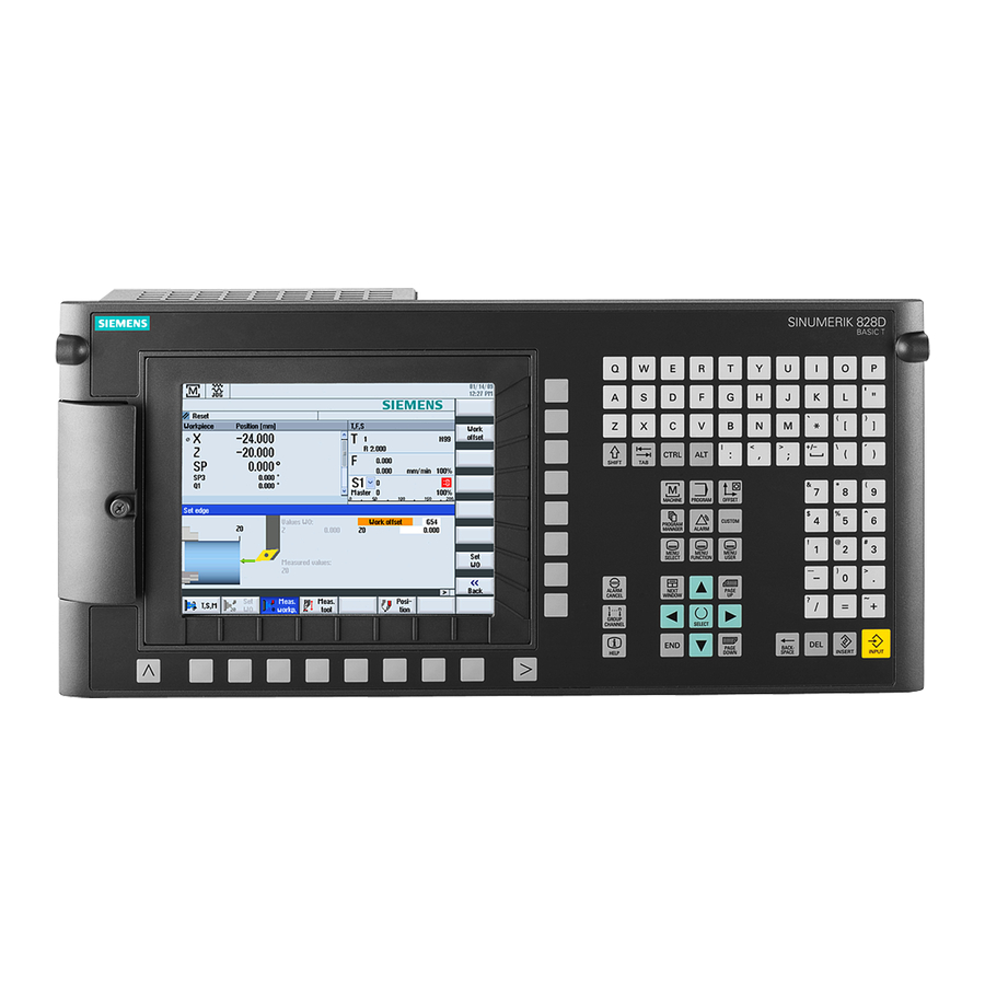
Page 23: Operator Controls And Display Elements
System description 2.4 Operator controls and display elements Operator controls and display elements TFT color display The TFT color display has a diagonal size of 10.4" (PPU 26x.3/28x.3) or 8.4" (PPU 24x.3). The resolution is 800 x 600 pixels. The softkeys are arranged in an 8 + 8 layout; this makes the CNC easy to operate using only a very small number of menu levels. - Page 24 System description 2.4 Operator controls and display elements Function corresponds to PC Function corresponds to PC key function key function Home CTRL key Page up ALT key Page down Delete Cursor up Insert Cursor left Enter Cursor right Cursor down 5 (in numeric key group) A ...
-
Page 25: Type Plate
System description 2.5 Type plate Type plate Type plates The PPU type plate is located on the rear side. Note The contents of the individual type plate fields on the current controller may differ from those described in this Manual (e.g. updated product status, approvals and identifications not yet issued, etc.). - Page 26 System description 2.5 Type plate Note MAC addresses The MAC addresses printed on the type plate of the PPU are required for configuring the PLC I/O Interface communications networks based on PROFINET and Industrial Ethernet. There is a similar situation for the machine control panels and the I/O modules. PPU and components Manual, 05/2015, 6FC5397-2DP40-3BA4...
-
Page 27: System Overview
System description 2.6 System overview System overview Configuration with four axes (basic configuration) The following configuration shows a typical example with SINAMICS S120 booksize: 1FK7 feed motor 1PH8 spindle motor 1FK7 feed motor 1FK7 feed motor Figure 2-5 Configuration example 1: Basic configuration with four axes PPU and components Manual, 05/2015, 6FC5397-2DP40-3BA4... - Page 28 System description 2.6 System overview Configuration with S120 Combi and six axes The following configuration shows the maximum expansion stage with SINAMICS S120 Combi: Figure 2-6 Configuration example 2: Maximum expansion stage with six axes and with Safety Integrated PPU and components Manual, 05/2015, 6FC5397-2DP40-3BA4...
-
Page 29: Connectable Components
A maximum of three handwheels can be connected. ● Mini handheld unit A mini HHU can be integrated into the SINUMERIK 828D system using a connection kit. ● I/O modules PP 72/48D PN / PP 72/48D 2/2A PN The modules are used to connect digital as well as analog inputs and outputs. To supply the module and the outputs, an external power supply unit (24 VDC) is required, which provides safety isolation from dangerous voltages. -
Page 30: Compactflash Cards
PPU and must be ordered as a separate component. The system CompactFlash card is essential for the operation of the PPU. In addition to the technology-specific system software for SINUMERIK 828D and the firmware for SINAMICS, the system CompactFlash card also contains: ●... -
Page 31: Inserting The System Compactflash Card
System description 2.8 CompactFlash Cards ● Only use memory cards that have been approved by Siemens for use with SINUMERIK. Even though SINUMERIK follows general industry standards for memory cards, it is possible that memory cards from some manufacturers will not function perfectly in this device or are not completely compatible with it (you can obtain information on compatibility from the memory card manufacturer or supplier). - Page 32 System description 2.8 CompactFlash Cards Figure 2-7 Mounting position Replacing the system CompactFlash card CAUTION Electrostatic Device (ESD) Before you touch a CompactFlash card, discharge yourself at the cabinet or at the ground terminal. The CompactFlash cards may only be inserted or removed when the control unit is disconnected from the power supply.
-
Page 33: Compactflash Card For User Data
System description 2.8 CompactFlash Cards 4. Pull out the CompactFlash card sideways. ③ 5. Gently insert the new CompactFlash card into slot until it clicks into place. ② 6. Re-attach the metal cover by first guiding it in backward, then tilting into the end position ①... - Page 34 System description 2.8 CompactFlash Cards Inserting the CompactFlash card To correctly insert the CompactFlash card in the slot, note the position the edge (arrow) in the figure below: Figure 2-8 Direction to insert the user CompactFlash card PPU and components Manual, 05/2015, 6FC5397-2DP40-3BA4...
-
Page 35: Application Planning
3.1.2 Grounding concept Components The SINUMERIK 828D system consists of a number of individual components which have been designed so that the system complies with the appropriate EMC and safety standards. The individual system components are: ● Panel Processing Unit PPU ●... - Page 36 Application planning 3.1 Secondary electrical conditions Shielded signal cable with reference ground Motor Encoder Equipotential bonding conductor Protective connection (via metal design or green-yellow protective conductors) Figure 3-1 Grounding concept The following rules apply for external cable cross sections: ● PA cross-section ≥ 10 mm ●...
-
Page 37: Ri Suppression Measures
However, if the system cannot operate without them, then the cable shields must be connected at both ends. Furthermore, the non-Siemens device must be connected to the controller via an equipotential bonding cable. Cable definitions The following cables are permissible: ●... - Page 38 Application planning 3.1 Secondary electrical conditions ● If signal lines cannot be routed a sufficient distance away from other cables, they must be installed in grounded cable ducts (metal). ● The clearance (interference injection area) between the following lines must be kept to a minimum: –...
-
Page 39: Climatic And Mechanical Environmental Conditions
● Original components and spare parts are used. This applies in particular to the use of specified cables and connectors. ● The equipment is correctly installed and commissioned. Standard requirements The SINUMERIK 828D system components meet the following standard requirements: Long-term storage EN 60721-3-1 Transport... -
Page 40: Operating Conditions
Application planning 3.2 Climatic and mechanical environmental conditions 3.2.3 Operating Conditions Note Before commissioning components with display, remove the foil which is used to protect the components during transport. Climatic environmental conditions If the specified values cannot be maintained, then a heat exchanger or air conditioner must be provided. - Page 41 The user must consider interference radiation for the complete system. Particular attention should be paid to cabling. Please contact your sales representative for assistance and support. If compliance with limit value class C2 is required, please contact your local Siemens sales partner.
-
Page 42: Recycling And Disposal
Application planning 3.3 Recycling and disposal Recycling and disposal Products should be disposed of corresponding to the relevant national regulations. The products described in this manual can be mostly recycled due to the fact that they contain very few damaging substances. To recycle and dispose of your old device in an environmentally friendly way, please contact an appropriate disposal company. -
Page 43: Installing
DANGER Risk of electric shock The entire system must be voltage-free when mounting or wiring the SINUMERIK 828D. Components in the control cabinet The SINAMICS components and the axis expansion modules are installed in a control cabinet. -
Page 44: Mounting Positions
Installing 4.1 Mounting positions Mounting positions Permitted mounting positions The PPU is secured with special tensioning elements and tensioners in the operator panel housing. The tensioners are included in the scope of delivery. Note Installing the PPU The maximum permissible tightening torque for the tensioning screws is 0.5 Nm and this value must not be exceeded. - Page 45 Installing 4.1 Mounting positions Panel cutout of the horizontal PPU variant ① Mounting frame ② Seal area ③ Pressure point for tensioners Figure 4-2 Horizontal PPU panel cutout PPU and components Manual, 05/2015, 6FC5397-2DP40-3BA4...
- Page 46 Installing 4.1 Mounting positions ① Mounting frame ② Tensioner (10 parts) ③ Seal ④ Shield contact ⑤ Grounding screw M5 ⑥ Interfaces Figure 4-3 Horizontal PPU mounting PPU and components Manual, 05/2015, 6FC5397-2DP40-3BA4...
- Page 47 Installing 4.1 Mounting positions Installation of the vertical PPU variant ① Mounting frame Figure 4-4 Clearance for ventilation and cables in the vertical PPU PPU and components Manual, 05/2015, 6FC5397-2DP40-3BA4...
- Page 48 Installing 4.1 Mounting positions Panel cutout of the vertical PPU variant ① Mounting frame ② Pressure point for tensioners ③ Seal area Figure 4-5 Vertical PPU panel cutout PPU and components Manual, 05/2015, 6FC5397-2DP40-3BA4...
- Page 49 Installing 4.1 Mounting positions ① Mounting frame ② Tensioner (10 parts) ③ Seal ④ Shield contact ⑤ Grounding screw M5 ⑥ Interfaces Figure 4-6 Installation of the vertical PPU variant PPU and components Manual, 05/2015, 6FC5397-2DP40-3BA4...
-
Page 50: Dimension Drawings
Installing 4.2 Dimension drawings Dimension drawings PPU horizontal Figure 4-7 Horizontal PPU dimensioning PPU and components Manual, 05/2015, 6FC5397-2DP40-3BA4... - Page 51 Installing 4.2 Dimension drawings PPU vertical Figure 4-8 Vertical PPU dimensioning PPU and components Manual, 05/2015, 6FC5397-2DP40-3BA4...
- Page 52 Installing 4.2 Dimension drawings PPU and components Manual, 05/2015, 6FC5397-2DP40-3BA4...
-
Page 53: Rules For Permitted Topologies
Optional: 2. direct sin/cos encoder for spindle (via SMx20) Remains empty when connecting a direct TTL spindle encoder via X220 In this case, the TTL encoder interface X220 remains free Table 5-2 Assigning the DRIVE-CLiQ interfaces to the SINUMERIK 828D (PPU) DRIVE-CLiQ interface Connection with X100... - Page 54 Rules for permitted topologies 5.1 Topology rules for S120 Combi DRIVE-CLiQ interface Connection with Second Single Motor Module X200 X201 of the first Single Motor Module X201 Remains empty X202 Motor encoder for feedrate 2nd expansion axis (via Sensor Module) Double Motor Module X200 X101 of the PPU...
-
Page 55: Topology Rules For S120 Booksize
Rules for permitted topologies 5.2 Topology rules for S120 Booksize Topology rules for S120 Booksize Introduction The following rules apply for wiring components with DRIVE-CLiQ. A distinction is made between DRIVE-CLiQ rules, which must always be observed, and recommended rules, which, when observed, do not require any subsequent changes to the topology when expansions are made. - Page 56 Rules for permitted topologies 5.2 Topology rules for S120 Booksize ● Ring wiring is not permitted. ● Components must not be double-wired. Figure 5-1 Example: DRIVE-CLiQ line at the X100 terminal (without Safety Integrated) ● The following applies to the booksize format: –...
- Page 57 Rules for permitted topologies 5.2 Topology rules for S120 Booksize ● The Active Line Module Booksize and the Motor Modules Booksize can be connected to one DRIVE-CLiQ line. ● Chassis Line Module and Motor Module are connected in series. ● To allow the following modules to be assigned automatically during the commissioning (device identification), they should be connected to a free DRIVE-CLiQ port on the associated Active Line Module/Motor Module: –...
- Page 58 Rules for permitted topologies 5.2 Topology rules for S120 Booksize ● The motor encoder must be connected to the associated power unit. Component Connecting the motor encoder via DRIVE-CLiQ Single Motor Module booksize X202 Double Motor Module booksize ● Motor connection X1: Encoder at X202 ●...
-
Page 59: Topology Rules For Safety Integrated Functions
Rules for permitted topologies 5.3 Topology rules for Safety Integrated functions Topology rules for Safety Integrated functions Number Port 1 at the PPU Port 2 at the PPU Port 3 at the PPU Example in the figure: of axes X100 X101 X102 SINAMICS S120 booksize... -
Page 60: Topology Example Without Safety Integrated Functions
Rules for permitted topologies 5.4 Topology example without Safety Integrated functions Topology example without Safety Integrated functions Note These wiring examples are valid using the standard clock cycle setting and do not take into account any Safety Integrated functions. For further notes on Safety Integrated functions, see the SINAMICS S120 Safety Integrated Function Manual. - Page 61 Rules for permitted topologies 5.4 Topology example without Safety Integrated functions Topology for the maximum configuration with SINAMICS S120 booksize and eight axes Figure 5-5 DRIVE-CLiQ wiring with NX PPU and components Manual, 05/2015, 6FC5397-2DP40-3BA4...
- Page 62 Rules for permitted topologies 5.4 Topology example without Safety Integrated functions Topology with SINAMICS S120 chassis and SINAMICS S120 booksize and eight axes Figure 5-6 DRIVE-CLiQ wiring with NX PPU and components Manual, 05/2015, 6FC5397-2DP40-3BA4...
-
Page 63: Topology Example With Safety Integrated Functions
Rules for permitted topologies 5.5 Topology example with Safety Integrated functions Topology example with Safety Integrated functions Note Additional notes on Safety Integrated functions are available under: SINAMICS S120 Safety Integrated Function Manual. Topology with SINAMICS S120 booksize and six plus two axes Figure 5-7 DRIVE-CLiQ wiring with Safety Integrated functions and NX PPU and components... - Page 64 Rules for permitted topologies 5.5 Topology example with Safety Integrated functions Topology with SINAMICS S120 booksize and five plus three axes Figure 5-8 DRIVE-CLiQ wiring with Safety Integrated functions and NX Note Please note the following conditions for the examples below: 1.
- Page 65 Rules for permitted topologies 5.5 Topology example with Safety Integrated functions Topology with SINAMICS S120 chassis and SINAMICS S120 booksize and six axes Figure 5-9 DRIVE-CLiQ wiring with Safety Integrated functions and without NX PPU and components Manual, 05/2015, 6FC5397-2DP40-3BA4...
- Page 66 Rules for permitted topologies 5.5 Topology example with Safety Integrated functions Topology with SINAMICS S120 chassis and SINAMICS S120 booksize and eight axes Figure 5-10 Example with Safety Integrated functions and with NX Note You can find an example with SINAMICS S120 Combi and Safety Integrated functions under Auto-Hotspot or in the SINAMICS S120 Combi Manual.
-
Page 67: Interface Description
Requirement DANGER Risk of electric shock Before you mount the SINUMERIK 828D or cable it, the complete system must be in a no- voltage condition. Definition The abbreviations used in "Signal type" column in the tables showing the pin assignment have... - Page 68 Interface description 6.1 Interface overview Connection options The following overview shows the interfaces and their connection options: Terminal Module SINUMERIK 828D Article number TM54F PPU 240.3/PPU 241.3 Prefabricated cable PPU 260.3/PPU 261.3 PPU 280.3/PPU 281.3 SINAMICS S120 DRIVE-CLiQ cable X100...
-
Page 69: Power Supply Connection
Interface description 6.2 Power supply connection Power supply connection 6.2.1 Requirements for the power supply Pin assignment at X1 screw-type terminal block Table 6-1 Pin assignment Signal name Signal type Meaning 24 VDC power supply Ground Protective ground Requirements of DC power supplies Interface X1 is intended exclusively for the connection of the external 24 V power supply, e.g. -
Page 70: Connecting The Power Supply
Interface description 6.2 Power supply connection Table 6-3 Technical data of the DC power supply Rated voltage According to EN 61131-2 24 V DC Voltage range (mean value) 20.4 VDC to 28.8 V DC Voltage range (dynamic) 18.5 to 30.2 V DC Voltage ripple peak-to-peak 5% (unfiltered 6-pulse rectifica‐... -
Page 71: Ethernet
Interface description 6.3 Ethernet Ethernet X130, X127 pin assignment Signal name Signal type Meaning Transmit data + Transmit data - Receive data + Receive data - The interfaces are designed for operation in full-duplex mode; in other words, the ports can be used for the sending as well as for the receiving of data packets. - Page 72 Interface description 6.3 Ethernet Cable specification for X130 and X127 Feature Version Connector type RJ45 socket with 180° cable outlet Cable type Industrial Ethernet cable (CAT5) Max. cable length 100 m Note The X127 interface does not support auto crossing. If the Ethernet port of the connected PC or modem does not support auto-crossing, a crossed Ethernet cable must be used.
-
Page 73: Plc I/O Interface Based On Profinet
Interface description 6.4 PLC I/O Interface based on PROFINET PLC I/O Interface based on PROFINET Pin assignment PN1, PN2 Signal name Signal type Meaning Transmit data + Transmit data - Receive data + N.C. Not assigned N.C. Not assigned Receive data - N.C. - Page 74 For the 828D, this is a normal state and does not represent incorrect behavior. Sync Green The SINUMERIK 828D task system is not synchronized to the send cycle of PLC I/O Inter‐ face. An internal substitute clock of the same size as the send clock is generated.
- Page 75 Interface description 6.4 PLC I/O Interface based on PROFINET Name Color Status Meaning Yellow Cyclic flashing NC operation Yellow Lights up Accessing the CompactFlash card. NOTICE CompactFlash card If the LED is lit, the CompactFlash card must not be removed! Non-compliance can result in damage to the CompactFlash card.
-
Page 76: Digital Inputs/Outputs
Interface description 6.5 Digital inputs/outputs Digital inputs/outputs Pin assignment for X122 Signal name Meaning Digital input 0 Digital input 1 Digital input 2 Digital input 3 DI16 DI16 Digital input 16 DI17 DI17 Digital input 17 MEXT2 Ground for pins 1...6 P24EXT1 +24 V power supply DI/DO8... - Page 77 Interface description 6.5 Digital inputs/outputs Connection notes 1. Recommended connection: If both inputs and outputs are operated on a digital inputs/outputs group, it is recommended that both the inputs and the outputs are fed with the same 24 VDC supply: Figure 6-1 Inputs and outputs on the same supply 2.
- Page 78 Interface description 6.5 Digital inputs/outputs Signal name NC variable Meaning MEXT3 Ground for pins 9, 10, 12, 13 DOUT3 $A_OUT[3] Digital NC output 3 DOUT4 $A_OUT[4] Digital NC output 4 MEXT3 Ground for pins 9, 10, 12, 13 X252 pin assignment Signal name NC variable Meaning...
- Page 79 3. Wire the digital outputs of the interface for connection of the actuators. 4. Insert the cable into the corresponding screw terminal. References More information about digital inputs/outputs can be found in: Basic Functions Function Manual, "PLC for SINUMERIK 828D" (P4) PPU and components Manual, 05/2015, 6FC5397-2DP40-3BA4...
-
Page 80: Terminal Connection Diagram
Interface description 6.5 Digital inputs/outputs 6.5.1 Terminal connection diagram The following figure shows the terminal connection diagram for the digital inputs/outputs of a PPU. Figure 6-3 Terminal connection diagram for digital inputs/outputs PPU and components Manual, 05/2015, 6FC5397-2DP40-3BA4... -
Page 81: Example: Connecting A Bero Inductive Proximity Switch
Interface description 6.5 Digital inputs/outputs 6.5.2 Example: Connecting a BERO inductive proximity switch Supplementary conditions The following rules must be observed when connecting a proximity switch: ● In principle, proximity switches can be connected to any input. ● Because both the DI input terminals and the parameterizable DI/DO terminals are isolated, the ground of the supply must be connected to the associated M terminal. -
Page 82: Technical Data
Interface description 6.5 Digital inputs/outputs 6.5.3 Technical data Note An open input is interpreted as "low". Note Terminals MEXT1 ... MEXT4 must be connected for the digital inputs/outputs to function. This can be done as follows: ● Connect the ground reference of the digital inputs. ●... - Page 83 Interface description 6.5 Digital inputs/outputs Parameter Value Voltage 18 V to 30 V Load current per output, maximum 0.5 A Load current per connector, maximum Signal propagation times L → H: 50 μs H → L: 200 μs Galvanic isolation Yes: The reference potential is terminal1M/1P24 (24 V Digital outputs Table 6-8...
-
Page 84: Drive-Cliq
Interface description 6.6 DRIVE-CLiQ DRIVE-CLiQ 6.6.1 DRIVE-CLiQ interface Pin assignment at X100 - X102 Signal name Signal type Meaning Transmit data + Transmit data - Receive data + Reserved Reserved Receive data - Reserved Reserved Reserved Reserved DRIVE-CLiQ interfaces are used to connect SINAMICS S120 components to the PPU. The following rules apply: ●... -
Page 85: Sinamics Components
● SINAMICS S120 Booksize Power Units with Cold Plate Manual ● SINAMICS S120 Combi Manual 6.6.2 SINAMICS components Components with DRIVE-CLiQ As a rule, all SINAMICS components approved for SINUMERIK 828D can be connected using DRIVE-CLiQ. Component Description NX10.3 / NX15.3 Axis expansion module Active / Basic / Smart Line Mod‐... - Page 86 Interface description 6.6 DRIVE-CLiQ Component Description SMC40 This Sensor Module is used to convert encoder signals from abso‐ lute encoders with EnDat 2.2 to DRIVE-CLiQ. DMC20 / DME20 DRIVE-CLiQ Hub Modules are used to implement the star-shaped distribution of a DRIVE-CLiQ line. TM54F The TM54F Terminal Module is a terminal expansion module for Safety Integrated functions.
-
Page 87: Handwheel
Max. two electronic handwheels can be connected to connector X143 on the rear of the PPU. Note The SINUMERIK 828D software can process up to max. 3 handwheels. You can connect 2 handwheels to the PPU. You can connect an additional handwheel to the machine control panel, see Anschließbare Komponenten (Page 93). - Page 88 Interface description 6.7 Handwheel The following diagrams indicate the different data transfer types: ● Differential signal transfer: Note Differential signal transfer is the preferred technique, as it is insensitive to electromagnetic disturbances. ● Asymmetrical signal transfer: PPU and components Manual, 05/2015, 6FC5397-2DP40-3BA4...
- Page 89 Interface description 6.7 Handwheel Cable specification Feature Version Connector type: 12-pin screw terminal Cable type: Twisted pair, shielded Article number 6FX8002-2BB01-1A□□ Max. cable length PPU and components Manual, 05/2015, 6FC5397-2DP40-3BA4...
-
Page 90: Usb
Interface description 6.8 USB The USB interfaces correspond to the norm and are, therefore, not described in detail here. ● The X125 USB interface (at the front behind a flap) can be used to connect a USB- FlashDrive for transferring user and commissioning data. ●... -
Page 91: Rs 232 Serial Interface
Interface description 6.9 RS 232 serial interface RS 232 serial interface Pin assignment Table 6-9 X140 pin assignment Signal name Signal type Meaning Not connected Serial receive data Serial transmit data Data terminal ready Ground (reference potential) Ready for operation Switch-on transmit section Clear to send Reserved... - Page 92 Interface description 6.9 RS 232 serial interface PPU and components Manual, 05/2015, 6FC5397-2DP40-3BA4...
-
Page 93: Anschließbare Komponenten
Description The MCP 483 USB machine control panel allows machine functions to be operated in a user- friendly way. It can be used with a SINUMERIK 828D control for machine-related operation of machine tools. The machine-specific keys have replaceable slide-in labels so that they can be adapted. -
Page 94: Operator Controls And Displays
Anschließbare Komponenten 7.1 MCP 483 USB 7.1.1 Operator controls and displays Operator controls (front) ① Slot for the Emergency Stop button ② JOG and reference point keys ③ Display for the tool number ④ Slots for control devices (d = 16 mm, e.g. switch) Drill mounting holes to install control devices. -
Page 95: Mounting
Anschließbare Komponenten 7.1 MCP 483 USB Emergency Stop circuit EMERGENCY STOP Press the Emergency Stop button in the following situations: ● When persons are at risk. ● When there is a risk of the machine or workpiece being damaged. As a rule, when operating the Emergency Stop button, all drives are brought to a standstill with max. - Page 96 Anschließbare Komponenten 7.1 MCP 483 USB Figure 7-2 Mounting panel cutout Dimension drawing WARNING Danger to life from hazardous voltage It is possible to reach into installation holes for control devices (shown in gray in the drawing). Make sure that no live parts can be touched behind the holes within a clearance of at least 85 mm (hatched area in the drawing).
-
Page 97: Connecting
Anschließbare Komponenten 7.1 MCP 483 USB 7.1.3 Connecting Connections (rear) ① Ground terminal ② USB connection for communication with the PPU, X10 NC ③ Slots for control devices (d = 16 mm) Figure 7-4 Connections at the rear USB 2.0 interface The machine control panel is connected to the PPU using a USB cable. - Page 98 Anschließbare Komponenten 7.1 MCP 483 USB Connections and switch settings of the override switch Connection designation: AA, BB Connector type: 7-pin COMBICON connector Encoding: Gray code PPU and components Manual, 05/2015, 6FC5397-2DP40-3BA4...
- Page 99 Anschließbare Komponenten 7.1 MCP 483 USB The machine control panel has two override switches for the feedrate and for the spindle. The switch positions with the associated values are listed in the following tables: ● You can read out the value for the feedrate override in the input image DB1000.DBB3.0...4. Position Value 0x01...
-
Page 100: Parameterization
Anschließbare Komponenten 7.1 MCP 483 USB 7.1.4 Parameterization Input image The specifications for assigning input and output bytes listed in the tables are defined as standard addresses in the PLC. Either one MCP USB or one MCP PN can be connected to the PPU, and therefore only DB1000 and DB1100 are described. - Page 101 Anschließbare Komponenten 7.1 MCP 483 USB DB1100 Byte Bit7 Bit6 Bit5 Bit4 Bit3 Bit2 Bit1 Bit0 DBB3 Travel com‐ mand in MCS/WCS DBB4 Freely assignable customer keys DBB5 Freely assignable customer keys DBB6 RESET DBB7 DBB8 7-segment display LED 1 DBB9 7-segment display LED 2 DBB10...
- Page 102 Anschließbare Komponenten 7.1 MCP 483 USB Some of the keys are permanently preassigned, the remaining keys can be freely assigned. The labeling of the permanently assigned keys are shown in brackets in the table. The keys are designated with S1 up to S40 in the following tables and diagrams. Port 0.0 Port 0.1 Port 0.2...
-
Page 103: Technical Data
Anschließbare Komponenten 7.1 MCP 483 USB 7.1.5 Technical data MCP 483 USB Parameter Value Input voltage 5 V DC Power consumption, max. 2.5 W Vibratory load: 10 – 58 Hz: 0.35 mm/58 - 200 Hz: 1 g ● Operation (3M6 acc. to EN 60721-3-3) ●... -
Page 104: Spare Parts And Accessories
Set of tension jacks Set of tension jacks for supplementary op‐ 6FC5248–0AF14–0AA0 erator components with 2.5 mm profile, 20mm length All spare parts currently available for a product can be found online at (www.siemens.com/ sow). PPU and components Manual, 05/2015, 6FC5397-2DP40-3BA4... - Page 105 Siemens provides a symbol library with key symbols. Customers can print their own slide-in labels using the A4 blank films included in the accessory pack. Siemens also provides a template file to print customized key labels. Copy the symbols from the symbol library to the required key position in the template.
-
Page 106: Mcp 310 Usb
The MCP 310 USB machiine control panel allows machine functions to be operated in a very user-friendly way. They can be used with a SINUMERIK 828D control for machine-level operation of machine tools. The machine-specific keys have replaceable slide-in labels so that they can be adapted. -
Page 107: Operator Controls And Displays
Anschließbare Komponenten 7.2 MCP 310 USB 7.2.1 Operator controls and displays Operator controls (front) ① Slot for the Emergency Stop button ② JOG and reference point keys ③ Display for the tool number ④ Slots for control devices (d = 16 mm, e.g. switch) Drill mounting holes to install control devices. -
Page 108: Mounting
Anschließbare Komponenten 7.2 MCP 310 USB Printed slide-in labels are included in the accessory pack for labeling key groups for operation in milling machines and lathes. You can individually label the customer keys, see Section Spare parts and accessories (Page 118). Blank slide-in labels are included in the accessory pack. Emergency Stop circuit EMERGENCY STOP Press the Emergency Stop button in the following situations:... - Page 109 Anschließbare Komponenten 7.2 MCP 310 USB The machine control panel is mounted from the front in a rectangular cut-out and attached using tension jacks (0.5 Nm tightening torque). The tension jacks are included in the scope of delivery. Tension jacks are also available as a spare part, see Section Spare parts and accessories (Page 118).
- Page 110 Anschließbare Komponenten 7.2 MCP 310 USB Figure 7-8 Dimensions and clearances PPU and components Manual, 05/2015, 6FC5397-2DP40-3BA4...
-
Page 111: Connecting
Anschließbare Komponenten 7.2 MCP 310 USB 7.2.3 Connecting Connections (rear) ① Ground terminal ② USB connection for communication with the PPU, X10 NC ③ Slots for control devices (d = 16 mm) Figure 7-9 Connections at the rear USB 2.0 interface The machine control panel is connected to the PPU using a USB cable. - Page 112 Anschließbare Komponenten 7.2 MCP 310 USB Maximum cable length: 0.8 m Type B socket Signal name Signal type Meaning + 5 V Data- Data - Data+ Data + Ground Connections and switch settings of the override switch Connection designation: AA, BB Connector type: 7-pin COMBICON connector Encoding: Gray code PPU and components...
- Page 113 Anschließbare Komponenten 7.2 MCP 310 USB The machine control panel has two override switches for the feedrate and for the spindle. The switch positions with the associated values are listed in the following tables: ● You can read out the value for the feedrate override in the input image DB1000.DBB3.0...4. Position Value 0x01...
-
Page 114: Parameterization
Anschließbare Komponenten 7.2 MCP 310 USB 7.2.4 Parameterization Input image The specifications for assigning input and output bytes listed in the tables are defined as standard addresses in the PLC. Either one MCP USB or one MCP PN can be connected to the PPU, and therefore only DB1000 and DB1100 are described. - Page 115 Anschließbare Komponenten 7.2 MCP 310 USB DB1100 Byte Bit7 Bit6 Bit5 Bit4 Bit3 Bit2 Bit1 Bit0 DBB3 Travel com‐ mand in MCS/WCS DBB4 Freely assignable customer keys S7 (coolant) DBB5 Freely assignable customer keys DBB6 RESET DBB7 DBB8 7-segment display LED 1 DBB9 7-segment display LED 2 DBB10...
- Page 116 Anschließbare Komponenten 7.2 MCP 310 USB Some of the keys are permanently preassigned, the remaining keys can be freely assigned. The labeling of the permanently assigned keys are shown in brackets in the table. Keys are designated with S1 to S39 in the following table and diagrams. Port 0.0 Port 0.1 Port 0.2...
-
Page 117: Technical Data
Anschließbare Komponenten 7.2 MCP 310 USB 7.2.5 Technical data MCP 310 USB Parameter Value Input voltage 5 V DC Power consumption, max. 2.5 W Vibratory load: 10 – 58 Hz: 0.35 mm/58 - 200 Hz: 1 g ● Operation (3M6 acc. to EN 60721-3-3) ●... -
Page 118: Spare Parts And Accessories
Set of tension jacks Set of tension jacks for supplementary op‐ 6FC5248–0AF14–0AA0 erator components with 2.5 mm profile, 20mm length All spare parts currently available for a product can be found online at (www.siemens.com/ sow). PPU and components Manual, 05/2015, 6FC5397-2DP40-3BA4... - Page 119 Siemens provides a symbol library with key symbols. Customers can print their own slide-in labels using the A4 blank films included in the accessory pack. Siemens also provides a template file to print customized key labels. Copy the symbols from the symbol library to the required key position in the template.
-
Page 120: Mcp 483C Pn
Description The MCP 483C PN machine control panel enables user-friendly operation of the machine functions. It can be used with a SINUMERIK 828D control for machine-related operation of machine tools. All keys are designed with replaceable caps for machine-specific adaptations. The key caps can be freely inscribed using laser. -
Page 121: Operator Controls And Display Elements
Anschließbare Komponenten 7.3 MCP 483C PN 7.3.1 Operator controls and display elements Operator controls (front) ① Emergency-Stop button ② Installation locations for control devices (d = 16 mm) ③ Reset button ④ Program control ⑤ Operating modes, machine functions ⑥ User keys T1 to T15 ⑦... - Page 122 Anschließbare Komponenten 7.3 MCP 483C PN Emergency Stop circuit EMERGENCY STOP Press the Emergency Stop button in emergency situations: ● When persons are at risk. ● When there is a risk of the machine or workpiece being damaged. As a rule, when operating the Emergency-Stop button, all drives are brought to a standstill with max.
- Page 123 Anschließbare Komponenten 7.3 MCP 483C PN Display elements (rear) ① Ground terminal ② Feed override X30 ③ Spindle override X31 ④ PLC I/O Interface X20/X21 connections ⑤ Slot for emergency stop ⑥ Installation locations for additional control devices (d = 16 mm) ⑦...
-
Page 124: Mounting
Anschließbare Komponenten 7.3 MCP 483C PN LEDs for status display When the system is booting, all three LEDs are lit. Name Designation Color Description PowerOK Green Lit: Power supply OK PNSync Green Lit: System software running, STOP state Flashes 0.5 Hz: System software running, RUN state PNFault Not lit: Module is operating without errors;... -
Page 125: Connecting
Anschließbare Komponenten 7.3 MCP 483C PN Tension jacks are also available as a spare part (see Section: "Spare parts and accessories (Page 135)"). Figure 7-13 Panel cutout of MCP 483C PN MCP 483C PN dimension drawing Figure 7-14 MCP 483C PN dimensions 7.3.3 Connecting 7.3.3.1... - Page 126 The Ethernet cables are not included in the scope of delivery. When connecting the machine control panel to the SINUMERIK 828D, please use the preassembled SINAMICS DRIVE-CLiQ signal cables; from a technical point of view, these are also suitable for use with PROFINET.
- Page 127 Anschließbare Komponenten 7.3 MCP 483C PN Signal name Signal type Meaning N.C. Not assigned N.C. Not assigned Receive - N.C. Not assigned N.C. Not assigned Rotary switch: Feed override X30 / spindle override X31 Connector designation: X30/X31 Connector type: 2 x 5-pin plug connector, according to EN 60603-13 with coding Table 7-4 Assignment of connector X30 Signal name...
- Page 128 Anschließbare Komponenten 7.3 MCP 483C PN Connector type: 4-pin plug connector Table 7-5 Assignment of connector X51 Signal name Signal type Meaning KT-IN1 Customer key 1 KT-IN2 Customer key 2 KT-IN3 Customer key 3 Ground Table 7-6 Assignment of connector X52 Signal name Signal type Meaning...
- Page 129 The handwheel is supplied by the MCP module with 5 V / 100 mA. An external power supply is not permitted. NOTICE Handwheel connections The SINUMERIK 828D software can process up to three handwheels. You can connect two handwheels to the PPU. You can connect an additional handwheel to the machine control panel. Connector designation:...
- Page 130 PLC I/O Interface PROFINET address "0" The two switches S2-9 and S2-10 must remain "ON". The switches S2-1 to S2-8 define the PROFINET address. For a SINUMERIK 828D, the address "64" must always be assigned to the MCP. PPU and components...
-
Page 131: Parameterization
Anschließbare Komponenten 7.3 MCP 483C PN Table 7-12 Settings of switch S2 Meaning PROFINET address "64" Further information on the addressing can be found in Section Addressing components (Page 256). 7.3.4 Parameterization The specifications for assigning input and output bytes listed in the tables are defined as standard addresses in the PLC. - Page 132 Anschließbare Komponenten 7.3 MCP 483C PN Byte Bit7 Bit6 Bit5 Bit4 Bit3 Bit2 Bit1 Bit0 EB123 KT-IN9 EB124 EB125 pin 6 pin 7 pin 8 pin 9 pin 10 Signals marked with * are inverse signals. 1) If the 4-stage spindle override rotary switch on X31 is replaced by a 5-stage rotary switch, the information here can be measured in 5 stages.
- Page 133 Anschließbare Komponenten 7.3 MCP 483C PN Byte Bit7 Bit6 Bit5 Bit4 Bit3 Bit2 Bit1 Bit0 AB117 Freely assignable customer keys AB118 RESET AB119 KT-OUT KT-OUT KT-OUT KT-OUT KT-OUT KT-OUT Signals marked with * are inverse signals Default key assignment Figure 7-17 Default key assignment of MCP 483C PN Assignment of the inputs (I) and outputs (O) to the keys and LEDs Figure 7-18...
-
Page 134: Technical Data
Anschließbare Komponenten 7.3 MCP 483C PN 7.3.5 Technical data MCP 483C PN Parameter Value Input voltage 24 V DC Power consumption, max. ● Board 43.2 W (6 x 7.2 W) *) ● Illumination 2 x 0.9 W ● Handwheels 50 W ●... -
Page 135: Spare Parts And Accessories
Anschließbare Komponenten 7.3 MCP 483C PN *) If the outputs for the illuminated pushbuttons (X53/X54) are loaded with the max. permissible current of 0.3 A, this results in additional power consumption of 36 W. The total power consumption is then 50 See also Other values/standards: Application planning (Page 35) 7.3.6... - Page 136 Anschließbare Komponenten 7.3 MCP 483C PN Table 7-18 Accessories available for order Component Description Amount Article number Square key cap, can be 1 set of 90, ergo-gray and 20 each 6FC5248–0AF12–0AA0 laser-labeled of red / green / yellow / medium gray Square key cap, for in‐...
-
Page 137: Mcp 310C Pn
The 310C PN machine control panel enables user-friendly operation of the machine functions. It can be used in the SINUMERIK 828D for machine-related operation of machine tools. All keys are designed with replaceable caps for machine-specific adaptations. The key caps can be freely inscribed using laser. -
Page 138: Operator Controls And Display Elements
Anschließbare Komponenten 7.4 MCP 310C PN 7.4.1 Operator controls and display elements Operator controls ① Operating modes and machine functions ② 16 customer keys ③ Spindle control ④ Slot for EMERGENCY STOP button or override switch for the spindle control ⑤... - Page 139 Anschließbare Komponenten 7.4 MCP 310C PN Mounting slots for control devices WARNING Warning of damage ⑥ Do not chip out the openings for mounting control devices ; drill them to the required width. Key caps All keys of the MCP 310C PN come with changeable key caps. Refer to the following table for the additional replacement key caps provided for lathes in the accessories pack: Key cap Symbol number...
- Page 140 Anschließbare Komponenten 7.4 MCP 310C PN ① Slot for Emergency-Stop button or spindle override ② Power supply interface X10 ③ X60 connection for handwheel, X61 reserved ④ Switch for setting the handwheel signal type ⑤ Switch S2 ⑥ LEDs ⑦ Ethernet cable strain relief ⑧...
-
Page 141: Mounting
Anschließbare Komponenten 7.4 MCP 310C PN LEDs for status display Table 7-19 LEDs Name Designation Color Description PowerOK Green Lit: Power supply ok PNSync Green Lit: System software running, STOP state Flashes 0.5 Hz: System software running, RUN state PNFault Not lit: Module is operating without errors;... - Page 142 Anschließbare Komponenten 7.4 MCP 310C PN Tension jacks The machine control panel is attached using six tension jacks (tightening torque, 0.5 Nm). Figure 7-21 Panel cut-out for the machine control panel MCP 310C PN PPU and components Manual, 05/2015, 6FC5397-2DP40-3BA4...
-
Page 143: Connecting
Anschließbare Komponenten 7.4 MCP 310C PN Dimension drawing ① In the sealing area ② Mounting frame ③ Tension jack (6 parts) - tightening torque 0.5 Nm Figure 7-22 MCP 310C PN dimensions 7.4.3 Connecting Securing the cables Two equivalent connections (Fast Ethernet) are available for establishing the PLC I/O Interface communication network based on PROFINET. - Page 144 The Ethernet cables are not included in the scope of delivery. When connecting the machine control panel to the SINUMERIK 828D, please use the preassembled SINAMICS DRIVE-CLiQ signal cables; from a technical point of view, these are also suitable for use with PROFINET.
- Page 145 Anschließbare Komponenten 7.4 MCP 310C PN Signal name Signal type Meaning N.C. Not assigned N.C. Not assigned Receive - N.C. Not assigned N.C. Not assigned Rotary switch: Feed override X30 / spindle override X31 Connector designation: X30/X31 Connector type: 2 x 5-pin plug connector, according to EN 60603-13 with coding Table 7-21 Assignment of connector X30 Signal name...
- Page 146 Anschließbare Komponenten 7.4 MCP 310C PN Connector type: 4-pin plug connector Table 7-22 Assignment of connector X51 Signal name Signal type Meaning KT-IN1 Customer key 1 KT-IN2 Customer key 2 KT-IN3 Customer key 3 Ground Table 7-23 Assignment of connector X52 Signal name Signal type Meaning...
- Page 147 The handwheel is supplied by the MCP module with 5 V / 100 mA. An external power supply is not permitted. NOTICE Handwheel connections The SINUMERIK 828D software can process up to three handwheels. You can connect two handwheels to the PPU. You can connect an additional handwheel to the machine control panel. Connector designation:...
- Page 148 PLC I/O Interface PROFINET address "0" The two switches S2-9 and S2-10 must remain "ON". The switches S2-1 to S2-8 define the PROFINET address. For a SINUMERIK 828D, the address "64" must always be assigned to the MCP. PPU and components...
-
Page 149: Parameterization
Anschließbare Komponenten 7.4 MCP 310C PN Table 7-29 Settings of switch S2 Meaning PROFINET address "64" Further information on the addressing can be found in Section Addressing components (Page 256). 7.4.4 Parameterization The specifications for assigning input and output bytes listed in the tables are defined as standard addresses in the PLC. - Page 150 Anschließbare Komponenten 7.4 MCP 310C PN Byte Bit7 Bit6 Bit5 Bit4 Bit3 Bit2 Bit1 Bit0 EB125 pin 6 pin 7 pin 8 pin 9 pin 10 Signals marked with * are inverse signals. If the 4-stage rotary spindle override switch on X31 is replaced by a 5-stage rotary switch, the input information here can be measured in 5 stages.
- Page 151 Anschließbare Komponenten 7.4 MCP 310C PN Default key assignment Figure 7-25 Default key assignment of MCP 310C PN Assignment of the inputs (I) and outputs (O) to the keys and LEDs Figure 7-26 Inputs and outputs of the MCP 310C PN keyboard PPU and components Manual, 05/2015, 6FC5397-2DP40-3BA4...
-
Page 152: Technical Data
Anschließbare Komponenten 7.4 MCP 310C PN 7.4.5 Technical data MCP 310C PN Parameter Value Input voltage 24 V DC Power consumption, max. ● Board 43.2 W (6 x 7.2 W) *) ● Illumination 2 x 0.9 W ● Handwheels 50 W ●... -
Page 153: Spare Parts And Accessories
Anschließbare Komponenten 7.4 MCP 310C PN *) If the outputs for the illuminated pushbuttons (X53/X54) are loaded with the max. permissible current of 0.3 A, this results in additional power consumption of 36 W. The total power consumption is then 50 See also Other values/standards: Chapter "Application planning (Page 35)"... -
Page 154: Mcp Interface Pn
Anschließbare Komponenten 7.5 MCP Interface PN MCP Interface PN Description In the SINUMERIK solution line control family, communication with the operator panels is via PROFINET (Industrial Ethernet). The MCP Interface PN module enables customer-specific machine control panels to be connected to a machine tool. Communication is handled via PROFINET RT or Industrial Ethernet. - Page 155 Anschließbare Komponenten 7.5 MCP Interface PN Illustration ① Type plate ② Terminal strips / connectors for operator controls ③ Diagnostics LED ④ PROFINET interface X2 (Industrial Ethernet 100 Mbit/s) ⑤ PROFINET interface X3 (Industrial Ethernet 100 Mbit/s) ⑥ Grounding screw M5 for potential equalization connection ⑦...
-
Page 156: Mounting
Anschließbare Komponenten 7.5 MCP Interface PN Name Function Status Meaning H501 BUS_SYNC Not lit No PROFINET communication. PROFINET is synchronized (STOP state). Flashes (0.5 PROFINET is synchronized (RUN state). H502 BUS_FAULT PROFINET group fault. H505 Temperature alarm (red) Lit At least one temperature limit is being exceeded. 7.5.1 Mounting Installation... -
Page 157: Connection
Anschließbare Komponenten 7.5 MCP Interface PN 7.5.2 Connection Position of the interfaces Figure 7-29 MCP Interface PN interfaces Interface overview 24 VDC power supply PROFINET interface PROFINET interface Interface for rotary switch feed override Interface for rotary switch spindle override X40/X41 Digital inputs (24 V) X51 / X52 / X55... - Page 158 Anschließbare Komponenten 7.5 MCP Interface PN Connector type: 2 x 5-pin plug connector, acc. to EN 60603-13 with coding Table 7-34 Assignment of connector X30 / X31 Signal name Signal type Meaning N.C. Not assigned N.C. Not assigned Ground N.C. Not assigned 5 V supply DI122.4 / DI123.4...
- Page 159 Anschließbare Komponenten 7.5 MCP Interface PN Table 7-36 X41 pin assignments Signal name Type Meaning DI125.5 24 V input 3 DI125.6 24 V input 4 DI125.7 24 V input 5 Ground Table 7-37 Technical data for X40, X41 Parameter Value Voltage: -3 V to 30 V Typical current consumption:...
- Page 160 Anschließbare Komponenten 7.5 MCP Interface PN Connector designation: X51, X52, X55 Connector type: 4-pin plug connector Special feature: No galvanic isolation Max. cable length: 0.6 m Table 7-38 Assignment of connector X51 Signal name Type Meaning DI124.0 Customer key 0 DI124.1 Customer key 1 DI124.2...
- Page 161 Anschließbare Komponenten 7.5 MCP Interface PN Digital outputs X53, X54, X56, X57, X58 The 15 outputs are provided to control lamps in the illuminated pushbuttons. Recommended are lamps with 1.2 W (50 mA). Figure 7-32 Block diagram X53, X54 and X56 to X58 Note Observe the utilization of the power supply The fifteen 24 V outputs are divided into 2 groups with 8 or 7 outputs each.
- Page 162 Anschließbare Komponenten 7.5 MCP Interface PN Table 7-43 Assignment of connector X54 Signal name Type Meaning DO120.0 24 V output 0 (group 1) DO120.1 24 V output 1 (group 1) DO120.2 24 V output 2 (group 1) Ground Table 7-44 Assignment of connector X56 Signal name Type...
- Page 163 The handwheel is supplied by the MCP module with 5 V / 100 mA. An external power supply is not permitted. NOTICE Handwheel connections The SINUMERIK 828D software can process up to three handwheels. You can connect two handwheels to the PPU. You can connect an additional handwheel to the machine control panel. Connector designation:...
- Page 164 Anschließbare Komponenten 7.5 MCP Interface PN Table 7-49 Assignment of connector X62 Signal name Type Meaning P5HW 5 V power supply Ground HW1_A Handwheel 1 pulses track A HW1_XA Handwheel 1 pulses track A (negated) HW1_B Handwheel 1 pulses track B HW1_XB Handwheel 1 pulses track B (negated) P5HW...
- Page 165 Anschließbare Komponenten 7.5 MCP Interface PN Connector designation: X111, X112, X113, X114 Connector type: 40-pin plug connector Special feature: No galvanic isolation, with interlock Max. cable length: Table 7-50 Assignment of connector X111 Signal name Type Signal name Type Ground Ground DI112.0 DO112.0...
- Page 166 Anschließbare Komponenten 7.5 MCP Interface PN Table 7-51 Assignment of connector X112 Signal name Type Signal name Type Ground Ground DI114.0 DO114.0 DI114.1 DO114.1 DI114.2 DO114.2 DI114.3 DO114.3 DI114.4 DO114.4 DI114.5 DO114.5 DI114.6 DO114.6 DI114.7 DO114.7 DI115.0 DO115.0 DI115.1 DO115.1 DI115.2 DO115.2 DI115.3...
- Page 167 Anschließbare Komponenten 7.5 MCP Interface PN Table 7-52 Assignment of connector X113 Signal name Type Signal name Type Ground Ground DI116.0 DO116.0 DI116.1 DO116.1 DI116.2 DO116.2 DI116.3 DO116.3 DI116.4 DO116.4 DI116.5 DO116.5 DI116.6 DO116.6 DI116.7 DO116.7 DI117.0 DO117.0 DI117.1 DO117.1 DI117.2 DO117.2 DI117.3...
- Page 168 Anschließbare Komponenten 7.5 MCP Interface PN Table 7-53 Assignment of connector X114 Signal name Type Signal name Type Ground Ground DI118.0 DO118.0 DI118.1 DO118.1 DI118.2 DO118.2 DI118.3 DO118.3 DI118.4 DO118.4 DI118.5 DO118.5 DI118.6 DO118.6 DI118.7 DO118.7 DI119.0 DO119.0 DI119.1 DO119.1 DI119.2 DO119.2 DI119.3...
-
Page 169: Parameter Assignment
PLC I/O Interface PROFINET address "0" The two switches S1-9 and S1-10 must remain set to "ON". The switches S1-1 to S1-8 define the PROFINET address. For a SINUMERIK 828D, the address "64" must always be assigned to the MCP. Table 7-57... - Page 170 Anschließbare Komponenten 7.5 MCP Interface PN Standard input image Table 7-59 MCP Interface PN input image Byte Bit7 Bit6 Bit5 Bit4 Bit3 Bit2 Bit1 Bit0 EB112 X111.17 X111.15 X111.13 X111.11 X111.9 X111.7 X111.5 X111.3 EB113 X111.33 X111.31 X111.29 X111.27 X111.25 X111.23 X111.21 X111.19...
- Page 171 Anschließbare Komponenten 7.5 MCP Interface PN Input image of the handwheels Table 7-61 Input image for handwheel data Byte Bit7 Bit6 Bit5 Bit4 Bit3 Bit2 Bit1 Bit0 EB m + 0 Handwheel 1 counter status (16-bit signed, low-order byte equals byte m + 0) EB m + 1 EB m + 2 Handwheel 2 counter status...
-
Page 172: Technical Data
Anschließbare Komponenten 7.5 MCP Interface PN 7.5.4 Technical data MCP Interface PN Parameter Value Input voltage 24 V DC Power consumption, max. 2.4 W ● Board 2 x 0.9 W ● Handwheels 54 W (15 x 3.6 W) ● Lamps 4 W (80 x 0.05 W) ●... -
Page 173: Electronic Handwheel
Anschließbare Komponenten 7.6 Electronic handwheel Electronic handwheel Description The portable electronic handwheel is intended for use in conjunction with machines. A magnetic bracket and spiral connection cable can be found on its enclosure. The magnetic bracket (retaining magnet) enables the handwheel to be attached to metallic surfaces. The portable electronic handwheel is an incremental encoder that generates signals according to how the manually operated wheel is rotated. - Page 174 Anschließbare Komponenten 7.6 Electronic handwheel Figure 7-35 Pulse diagram PPU and components Manual, 05/2015, 6FC5397-2DP40-3BA4...
-
Page 175: Mounting
Anschließbare Komponenten 7.6 Electronic handwheel 7.6.1 Mounting Dimensions of the electronic handheld handwheel Figure 7-36 Front view and side view Additional options Optionally, the handheld electronic handwheel can be stored in a screw-on holder. The holder is mounted using three M4 screws (included in the scope of delivery). See also: Mini handheld unit, Chapter "Mounting (Page 181)"... -
Page 176: Connection
Anschließbare Komponenten 7.6 Electronic handwheel 7.6.2 Connection Electrical connection diagram The handheld handwheel is connected via a flange socket using the spiral connection cable. You will find article numbers for the recommended flange socket in Chapter Spare parts and accessories (Page 178). Note If a connected handwheel triggers pulses while in the idle position or when there is only minimal contact, connect it the opposite way round to what is stated on the label. -
Page 177: Technical Specifications
Anschließbare Komponenten 7.6 Electronic handwheel 7.6.3 Technical specifications Handheld electronic handwheel Parameter Value Operating voltage 5 V DC ± 5% Current consumption Max. 80 mA Limit frequency 10 kHz Number of pulses 100 S/R Displacement of phase A to B, typical 90°... -
Page 178: Spare Parts And Accessories
Anschließbare Komponenten 7.6 Electronic handwheel 7.6.4 Spare parts and accessories Accessories The following components are available as accessories for the handheld electronic handwheel: Component Description Article number Flange socket 9-pin flange socket 6FC9341-1AQ Holder including three M4 screws 6FX2006-1BG70 PPU and components Manual, 05/2015, 6FC5397-2DP40-3BA4... -
Page 179: Mini Handheld Unit
Anschließbare Komponenten 7.7 Mini handheld unit Mini handheld unit Description The mini handheld unit (Mini HHU) is a small easy-to-handle unit for setting up and operating simple machines in the JobShop area or similar applications. Special attention has been paid in the design to ergonomics and logical layout of the control elements. -
Page 180: Operator Controls
Anschließbare Komponenten 7.7 Mini handheld unit 7.7.1 Operator controls Control elements of the mini handheld unit Features of the operator controls: ● Emergency Stop button The EMERGENCY STOP button must be pressed in the following emergency situations: – When a person is at risk. –... -
Page 181: Mounting
Anschließbare Komponenten 7.7 Mini handheld unit 7.7.2 Mounting Dimensions of the mini handheld unit Figure 7-38 Dimension drawing of the mini HHU PPU and components Manual, 05/2015, 6FC5397-2DP40-3BA4... - Page 182 Anschließbare Komponenten 7.7 Mini handheld unit Installing the connection kit Procedure: 1. Transfer the hole pattern to the wall of the controller housing. Figure 7-39 Hole pattern for mounting 2. Insert the connection wires through the large drill hole into the controller housing. 3.
- Page 183 Anschließbare Komponenten 7.7 Mini handheld unit Additional options For the mini HHU, the following accessories can optionally be used: ● Angled socket An angled socket is available as an option, which permits the cable outlet direction to be rotated through 90°. Note The angled socket can only be used in conjunction with the non-assembled connection kit.
- Page 184 Anschließbare Komponenten 7.7 Mini handheld unit ● Adapter plate To install the metal flange socket in the location for plastic flange sockets, an adapter plate is available. Figure 7-41 Dimension drawing of the adapter plate ● Holder The mini HHU can be stored in a screw-on holder; this enables safe storage even on non- magnetic surfaces.
-
Page 185: Connecting
You can also connect the mini HHU to the MCP Interface PN module: ● The selection switch at X51 ● The function keys at X52 and X55 ● The handwheel at X60 / X62 Note that the SINUMERIK 828D software can process up to three handwheels. PPU and components Manual, 05/2015, 6FC5397-2DP40-3BA4... - Page 186 Anschließbare Komponenten 7.7 Mini handheld unit Circuit diagram 4x2x0.56mm² 5x2x0.25mm² 5x2x0.25mm² Blue brbl Brown blue Brown gebr Yellow brown Yellow grbr Gray brown Green grrs Gray pink Gray rsbr Pink brown Pink rtbl Red blue wsbl White blue Black wsge White yellow Violet wsgr...
-
Page 187: Parameterization
Parameterization Note The mini HHU can only be operated with a Siemens machine control panel of the PN type. If a mini HHU is connected, the functional assignment listed in the table below is valid for customer keys KT1 to KT9. On machine control panels MCP 310C PN and MCP 483C PN, the customer keys are assigned to input bytes IB122 and IB123. -
Page 188: Technical Data
Anschließbare Komponenten 7.7 Mini handheld unit When the mini HHU is connected, the customer keys (inputs) are not available for other applications. Table 7-64 Input image for MCP 310C PN and MCP 483C PN Byte Bit7 Bit6 Bit5 Bit4 Bit3 Bit2 Bit1 Bit0... - Page 189 Anschließbare Komponenten 7.7 Mini handheld unit Parameter Value Handwheel 100 pulses/rev Handwheel signals RS422 Emergency Stop button 24 V DC, 2 A 2 x NC contact Enabling buttons 24 V DC 2 x NO contacts Axis selector switch 24 V DC: 0.2 W Gray code Degree of protection without shaft input ac‐...
-
Page 190: Spare Parts And Accessories
Anschließbare Komponenten 7.7 Mini handheld unit Element Specification Jog key: positive traversing direction Jog key: negative traversing direction Jog key: rapid traverse for jog keys and handwheel Function keys F1, F2, F3 NO contact ● Switching current max. 0.1 A max. - Page 191 Anschließbare Komponenten 7.7 Mini handheld unit Accessories The following components are available as accessories for the mini handheld unit: Component Description Article number Connection kit Assembled, metal version, with terminat‐ 6FX2006-1BG20 ing connector Connection kit Assembled, metal version, without dum‐ 6FX2006-1BG25 my plug Connection kit...
-
Page 192: Pp 72/48D Pn
Anschließbare Komponenten 7.8 PP 72/48D PN PP 72/48D PN 7.8.1 Description Features The I/O module is a simple module (without a separate enclosure) for connecting digital and analog input/outputs as part of an automation system based on PROFINET IO. The module has the following important features: ●... - Page 193 Anschließbare Komponenten 7.8 PP 72/48D PN Illustration Figure 7-46 PP 72/48D PN I/O module PPU and components Manual, 05/2015, 6FC5397-2DP40-3BA4...
- Page 194 Anschließbare Komponenten 7.8 PP 72/48D PN Type plate The type plate and the MAC address label are on the rear side of the mounting plate. It is advisable to make a note of relevant data as it is no longer visible after installation. Figure 7-47 PP 72/48D PN type plate LED for status displays...
-
Page 195: Mounting
Anschließbare Komponenten 7.8 PP 72/48D PN Note When the system is booting, LEDs H1, H2 and H3 are lit. 7.8.2 Mounting Mounting The I/O module is screwed with a mounting plate to the control cabinet wall in the control cabinet. The module must be installed according to EN 60204. WARNING Protection against electric shock A protective conductor must be connected using the grounding screw. - Page 196 Anschließbare Komponenten 7.8 PP 72/48D PN Dimension drawing Figure 7-48 PP 72/48D PN dimensions PPU and components Manual, 05/2015, 6FC5397-2DP40-3BA4...
-
Page 197: Connecting
Anschließbare Komponenten 7.8 PP 72/48D PN 7.8.3 Connecting Connection options SINUMERIK Article number I/O module Prefabricated cable PP 72/48D PN PP 72/48D 2/2A PN Power supply 24 VDC SINUMERIK 828D/828D BASIC 6SL3060-4A..0-0AA0 SINUMERIK 840D sl (in fixed lengths) PROFINET 6FX2002-1DC00-1..0 I/O module (one meter accuracy) Port 2 X2... -
Page 198: X1 Power Supply
Anschließbare Komponenten 7.8 PP 72/48D PN 7.8.3.1 X1 power supply Requirements for the power supply DANGER Risk of lightning strike In the case of supply lines > 10 m, protectors must be installed at the device input in order to protect against lightning (surge). - Page 199 Anschließbare Komponenten 7.8 PP 72/48D PN Digital outputs To supply (24 V DC) the digital outputs, an additional external power supply source is required. The power supply is connected to terminals X111, X222 and X333 via pins 47, 48, 49 and 50 (DOCOMx).
-
Page 200: X2 Profinet
The I/O module has certified PROFINET interfaces, however their functionality cannot be fully utilized within the scope of the SINUMERIK 828D control system. Networking within SINUMERIK 828D is performed via a PLC I/O interface, which is based on PROFINET. Data transmission rate and cables The interfaces are designed for full-duplex mode;... - Page 201 Anschließbare Komponenten 7.8 PP 72/48D PN Pin assignment Table 7-70 Pin assignment - PROFINET X2, Port 1 and Port 2 Signal name Signal type Meaning Transmit data + Transmit data - Receive data + N.C. Not assigned N.C. Not assigned Receive data - N.C.
-
Page 202: X111, X222 And X333 Pin Assignment
Anschließbare Komponenten 7.8 PP 72/48D PN Note A newly set PROFINET address will only come into effect after power OFF/ON. The switch positions 9 and 10 guarantee the PROFINET functionality of the module and must always be switched "ON". Further information on the addressing can be found in Section Addressing components (Page 256). - Page 203 Anschließbare Komponenten 7.8 PP 72/48D PN Table 7-74 Pin assignment for X222 Signal name Type Signal name Type P24OUT DI 3.0 DI 3.1 DI 3.2 DI 3.3 DI 3.4 DI 3.5 DI 3.6 DI 3.7 DI 4.0 DI 4.1 DI 4.2 DI 4.3 DI 4.4 DI 4.5...
-
Page 204: Specification Of The Digital Inputs
Anschließbare Komponenten 7.8 PP 72/48D PN Signal name Type Signal name Type DI 8.2 DI 8.3 DI 8.4 DI 8.5 DI 8.6 DI 8.7 Not assigned Not assigned Not assigned Not assigned DO 4.0 DO 4.1 DO 4.2 DO 4.3 DO 4.4 DO 4.5 DO 4.6... - Page 205 Anschließbare Komponenten 7.8 PP 72/48D PN ① When using the internal power supply P24OUT ② When using the external power supply P24OUT Figure 7-50 Terminal assignment for the digital inputs Power supply for digital inputs (X111, X222, X333: Pin 2): The internal power supply (P24OUT) is taken from the general power supply of module X1, pin 2 (P24).
-
Page 206: Specification Of The Digital Outputs
Anschließbare Komponenten 7.8 PP 72/48D PN 7.8.3.5 Specification of the digital outputs Terminal assignment for the digital outputs The following figure shows an example of the terminal assignment for the digital outputs on connector X111. Connectors X222 and X333 are assigned analogously. Figure 7-51 Terminal assignment for the digital outputs NOTICE... -
Page 207: Parameter Assignment
Anschließbare Komponenten 7.8 PP 72/48D PN Digital outputs min. Typical max. Nominal Leakage current at low level 50 μA 400 μA Signal delay time T 0.5 ms Maximum switching frequency Resistive load 100 Hz Inductive load 2 Hz Lamp 11 Hz ×... - Page 208 Anschließbare Komponenten 7.8 PP 72/48D PN Terminal Byte Bit7 Bit6 Bit5 Bit4 Bit3 Bit2 Bit1 Bit0 Pin10 Pin9 Pin8 Pin7 Pin6 Pin5 Pin4 Pin3 DI 3.7 DI 3.6 DI 3.5 DI 3.4 DI 3.3 DI 3.2 DI 3.1 DI 3.0 Pin18 Pin17 Pin16...
-
Page 209: Diagnostics Via Input Image
Anschließbare Komponenten 7.8 PP 72/48D PN Terminal Byte Bit7 Bit6 Bit5 Bit4 Bit3 Bit2 Bit1 Bit0 Pin38 Pin37 Pin36 Pin35 Pin34 Pin33 Pin32 Pin31 DO 4.7 DO 4.6 DO 4.5 DO 4.4 DO 4.3 DO 4.2 DO 4.1 DO 4.0 X333 Pin46 Pin45... - Page 210 Anschließbare Komponenten 7.8 PP 72/48D PN Note The "alive and well" counter is a 3 bit modulo counter on a PP application level. The PP application can be monitored using this counter. Failure of the application software does not generally result in a communication failure, as this is developed in a hardware-supported manner.
-
Page 211: Technical Data
Anschließbare Komponenten 7.8 PP 72/48D PN Value Cause Effect Remedy byte 1 Internal error, system error The "PNFault" LED is activated. The firmware has detected a system er‐ ror, this status can only be exited by The outputs are disabled. means of a switch-on / switch-off. - Page 212 Anschließbare Komponenten 7.8 PP 72/48D PN Parameter Value Ambient temperature: -40 ... 70 °C ● Storage -40 ... 70 °C ● Transport 0 ... 55 °C ● Operation Dimensions: 300 mm ● Width 150 mm ● Height 35 mm ● Depth Weight, approx.
-
Page 213: Pp 72/48D 2/2A Pn
Anschließbare Komponenten 7.9 PP 72/48D 2/2A PN PP 72/48D 2/2A PN 7.9.1 Description Features The I/O module is a simple module (without a separate enclosure) for connecting digital and analog input/outputs as part of an automation system based on PROFINET IO. The module has the following important features: ●... - Page 214 Anschließbare Komponenten 7.9 PP 72/48D 2/2A PN Illustration Figure 7-52 PP 72/48D 2/2A PN I/O module PPU and components Manual, 05/2015, 6FC5397-2DP40-3BA4...
- Page 215 Anschließbare Komponenten 7.9 PP 72/48D 2/2A PN Type plate The type plate and the MAC address label are on the rear side of the mounting plate. It is advisable to make a note of relevant data as it is no longer visible after installation. Figure 7-53 PP 72/48D 2/2A PN type plate LEDs for status display...
-
Page 216: Assembling
Anschließbare Komponenten 7.9 PP 72/48D 2/2A PN Name Designation Color Description DIAG2 Green Reserved OVTemp Overtemperature indication Note When the system is booting, LEDs H1, H2 and H3 are lit. 7.9.2 Assembling Mounting The I/O module is screwed with a mounting plate to the control cabinet wall in the control cabinet. - Page 217 Anschließbare Komponenten 7.9 PP 72/48D 2/2A PN Dimension drawing Figure 7-54 PP 72/48D 2/2A PN dimension drawing PPU and components Manual, 05/2015, 6FC5397-2DP40-3BA4...
-
Page 218: Connection
Anschließbare Komponenten 7.9 PP 72/48D 2/2A PN 7.9.3 Connection Connection options SINUMERIK Article number I/O module Prefabricated cable PP 72/48D PN PP 72/48D 2/2A PN Power supply 24 VDC SINUMERIK 828D/828D BASIC 6SL3060-4A..0-0AA0 SINUMERIK 840D sl (in fixed lengths) PROFINET 6FX2002-1DC00-1..0 I/O module (one meter accuracy) -
Page 219: X1 Power Supply
Anschließbare Komponenten 7.9 PP 72/48D 2/2A PN Note Digital and analog signals must not be laid together within a cable. See also Addressing components (Page 256) 7.9.3.1 X1 power supply Requirements for the power supply DANGER Risk of lightning strike In the case of supply lines >... - Page 220 Anschließbare Komponenten 7.9 PP 72/48D 2/2A PN Digital inputs The 24 V supplied at X1 are used to supply the 72 digital inputs. If the internal supply voltage is not used to supply the digital inputs, this can optionally be replaced by an external power supply (24 V DC).
- Page 221 Anschließbare Komponenten 7.9 PP 72/48D 2/2A PN Pin assignment Table 7-89 Pin assignment at X1 screw-type terminal block Signal name Signal type Meaning 24 VDC power supply Ground Protective ground Power requirement 0.7 A (at 24 V DC) for PP 72/48D 2/2A PN and digital inputs plus 3 x 4 A at X111, X222 and X333 for supplying digital outputs.
-
Page 222: X2 Profinet
The I/O module has certified PROFINET interfaces, however their functionality cannot be fully utilized within the scope of the SINUMERIK 828D control system. Networking within SINUMERIK 828D is performed via a PLC I/O interface, which is based on PROFINET. Data transmission rate and cables The interfaces are designed for full-duplex mode;... -
Page 223: X111, X222 And X333 Pin Assignment
Anschließbare Komponenten 7.9 PP 72/48D 2/2A PN Name Color Status Meaning Activity Yellow Sending or receiving No activity PROFINET address (S1) The right logical address must be assigned to the I/O module for communication with PLC I/O interface using the 10 bit DIP switch S1. Table 7-93 Switch S1 settings Device name... - Page 224 Anschließbare Komponenten 7.9 PP 72/48D 2/2A PN Signal name Type Signal name Type DI 1.6 DI 1.7 DI 2.0 DI 2.1 DI 2.2 DI 2.3 DI 2.4 DI 2.5 DI 2.6 DI 2.7 Not assigned Not assigned Not assigned Not assigned DO 0.0 DO 0.1 DO 0.2...
- Page 225 Anschließbare Komponenten 7.9 PP 72/48D 2/2A PN Signal name Type Signal name Type DO 3.0 DO 3.1 DO 3.2 DO 3.3 DO 3.4 DO 3.5 DO 3.6 DO 3.7 DOCOM2 DOCOM2 DOCOM2 DOCOM2 VI: Voltage input/VO: Voltage Output I: Signal input/O: Signal output/GND: Reference potential (ground) Table 7-96 Pin assignment for X333 Signal name...
-
Page 226: Specification Of The Digital Inputs
Anschließbare Komponenten 7.9 PP 72/48D 2/2A PN Cable specification: ● 50-pin ribbon cable connector: 50-pin insulation piercing connecting device with strain relief, ribbon cables and terminal converter are required to connect the digital inputs and outputs. ● The required connecting cables (ribbon cables) must be provided by the user. Maximum cable length: 30 m 7.9.3.4 Specification of the digital inputs... -
Page 227: Specification Of The Digital Outputs
Anschließbare Komponenten 7.9 PP 72/48D 2/2A PN The internal power supply (P24OUT) is taken from the general power supply of module X1, pin 2 (P24). Alternatively, an external power supply can be connected if the load at the digital outputs becomes too high. Technical data Electrical specification of the digital inputs: Digital inputs... -
Page 228: Analog X3 Inputs/Outputs
Anschließbare Komponenten 7.9 PP 72/48D 2/2A PN NOTICE Protection against short circuit A max. current of I = 0.25 A at X111, X222, X333 where the demand factor is 100%: Pin 2 must not be exceeded. Characteristics: ● No galvanic isolation. ●... - Page 229 Anschließbare Komponenten 7.9 PP 72/48D 2/2A PN Wiring analog inputs/outputs Procedure: 1. Strip cable for analog signals. 2. Secure the stripped connection piece of the cable with the shield connection clamp. NOTICE Shield contact If the analog inputs/outputs are wired, a shielded lead must be used. The shield must be supported.
- Page 230 Anschließbare Komponenten 7.9 PP 72/48D 2/2A PN Cycle time of the analog value accumulation: 20 ms per channel Table 7-99 Technical specifications in the "voltage input" operating mode Parameter Value Input range (rated value) - 10 V to + 10 V permitted overrange - 11.75 V to + 11.75 V Resolution...
- Page 231 Anschließbare Komponenten 7.9 PP 72/48D 2/2A PN Measurements with 4-wire connections compensate for line resistances and return a considerably higher degree of precision in comparison with 2-wire connections. 1, 2 ADU Analog Digital Unit Constant current Figure 7-58 PT100 pin assignment Measurement using a 3-wire connection system The following pins must be jumpered at connector X3 in order to perform the measurement in the PT100 using a 3-wire connection system:...
- Page 232 Anschließbare Komponenten 7.9 PP 72/48D 2/2A PN Analog outputs The module has two analog outputs. These can optionally be assigned parameters as voltage or current output. Note The analog outputs are only enabled following the parameter assignment. From the switch-on of the I/O module to its enabling, the analog outputs do not read 0 V, but are defined by a voltage pulse at -0.2 V.
-
Page 233: Assigning Parameters
Anschließbare Komponenten 7.9 PP 72/48D 2/2A PN 7.9.4 Assigning parameters 7.9.4.1 Input / output images Input image The image comprises 3 slots (n, m, d ≙ start address, see Addressing components (Page 256)): ● Slot 1: Digital inputs (DI) – n+0 … n+8 (9 byte) –... - Page 234 Anschließbare Komponenten 7.9 PP 72/48D 2/2A PN Byte Bit7 Bit6 Bit5 Bit4 Bit3 Bit3 Bit1 Bit0 AI 0.7 AI 0.6 AI 0.5 AI 0.4 AI 0.3 AI 0.2 AI 0.1 AI 0.0 AI 1.15 AI 1.14 AI 1.13 AI 1.12 AI 1.11 AI 1.10 AI 1.9...
-
Page 235: Diagnostics Via Input Image
Anschließbare Komponenten 7.9 PP 72/48D 2/2A PN 7.9.4.2 Diagnostics via input image Table 7-108 Diagnostics input image Byte Bit7 Bit6 Bit5 Bit4 Bit3 Bit3 Bit1 Bit0 count_2 count_1 count_0 T_Alarm_2 T_Alarm_1 Diag_2 Diag_1 Diag_0 Status_1 Table 7-109 Messages in byte 0 Signal name Message count_2... - Page 236 Anschließbare Komponenten 7.9 PP 72/48D 2/2A PN Table 7-111 Elimination of error at "alive and well" counter status "2" Value Cause Effect Remedy byte 1 In the temperature measure‐ The "PNFault" LED is activated. It is essential that a Pt100 element is ment operating mode, an in‐...
-
Page 237: Assigning Parameters To The Analog Inputs / Outputs
The control type must be specified in the Analog Control Byte m+1 (bit 0), so that the 16 bit input and output values from and for the analog module are correctly interpreted by the control. In the SINUMERIK 828D control, the value "1" must be entered. Note The control type must be set prior to the operating mode so that the first set of user data is not misinterpreted. - Page 238 Anschließbare Komponenten 7.9 PP 72/48D 2/2A PN Operating mode 2nd channel Bit 3 Bit 2 Current measurement Temperature measurement (Pt100) Assigning parameters to the analog outputs The analog outputs (AO) can be operated in the following operating modes: Operating mode 3rd channel Bit 5 Bit 4 No operating mode...
-
Page 239: Analog Value Representation
Anschließbare Komponenten 7.9 PP 72/48D 2/2A PN Examples of programming 1. Determine control type: 2. Set the operating mode: 3. Query the error status bit in cyclic operation: 7.9.4.4 Analog value representation Note The analog values of the inputs and outputs are written or read in 16 bit data format i.e. they must be accessed word by word. - Page 240 Anschließbare Komponenten 7.9 PP 72/48D 2/2A PN Analog inputs Table 7-113 Measured values in the voltage measurement operating mode 16 bit value (hex.) 16 bit value (dec.) Factor Voltage value [V] Overflow Deactivation Overrange Up to 11.75 V 0x19B5 6581 10 V 0x0CDA 3291...
- Page 241 Anschließbare Komponenten 7.9 PP 72/48D 2/2A PN Note If a Pt100 element is accidentally not connected in this operating mode and an input voltage higher than 0.25 V is output, the analog module automatically switches to the "no operating mode" operating mode and resets the gain factor to "1". This is signalized in Status Word 0 (channel-specific) in the input image.
-
Page 242: Examples
Anschließbare Komponenten 7.9 PP 72/48D 2/2A PN 7.9.4.5 Examples Measured values and responses The following examples for assigning parameters to analog inputs/outputs are provided for the I/O module with device number "7". Example for operating mode voltage measurement Address Voltage ±10 V 2.5 V 10 V 12 V... -
Page 243: Technical Data
Anschließbare Komponenten 7.9 PP 72/48D 2/2A PN Address Current 20 mA 0 mA 5 mA 20 mA 22 mA PNFault LED Troubleshooting Deactivating/ activating Example for operating mode temperature measurement Address Pt100 Incorrect operating mode Resistor is not connected Operating mode QB72 16#AA 16#0F... - Page 244 Anschließbare Komponenten 7.9 PP 72/48D 2/2A PN Parameter Value Condensation Not permitted Relative humidity: 5 ... 95 % no condensation ● Storage 5 ... 95 % no condensation ● Transport 5 ... 90 % no condensation ● Operation Ambient temperature: -40 ...
-
Page 245: Description
Description Properties Using this module, you can expand the performance of an axis grouping of the SINUMERIK 828D CNC automation system. With an NX10.3 Numeric Control Extension, the PPU is able to control up to 8 axes. Type plate The NX10.3 module type plate contains the following basic information: Figure 7-59 NX10.3 type plate... - Page 246 Anschließbare Komponenten 7.10 NX10.3 Illustration The NX10.3 has the following interfaces: ● 4 DRIVE-CLiQ (X100 – X103) ● 6 digital inputs and 4 digital inputs/outputs (X122) ● Power supply (X124) Figure 7-60 Illustration of the NX10.3 (without cover) PPU and components Manual, 05/2015, 6FC5397-2DP40-3BA4...
- Page 247 Anschließbare Komponenten 7.10 NX10.3 LEDs for status display The following status displays on the NX10.3 provide information about the module state: LEDs Color Status Description Electronic power supply outside permissible tolerance range Green Continuous light NX10.3 is ready for operation. Flashing 2 Hz Writing to CompactFlash card Continuous light...
-
Page 248: Mounting
Anschließbare Komponenten 7.10 NX10.3 7.10.2 Mounting Designs The NX10.3 is integrated into the SINAMICS drive line-up. For the preferred installation sequence, the NX module should be mounted at the side of the Line Module. NOTICE Protection against overheating The 80 mm ventilation spaces above and below the components must be observed. PPU and components Manual, 05/2015, 6FC5397-2DP40-3BA4... - Page 249 Anschließbare Komponenten 7.10 NX10.3 Mounting aids Figure 7-61 NX10.3 mounting aids Mounting an NX10.3 on an Active Line Module Procedure: 1. Remove the spacers from the NX. 2. Position the NX on the left-hand side of the Line Module. The mounting fixtures fit exactly in the five cutouts on the NX.
-
Page 250: Connecting
Anschließbare Komponenten 7.10 NX10.3 Dimension drawing Figure 7-62 NX10.3 dimensions 7.10.3 Connecting Power supply X124 Connector designation: X124 Connector type: Screw terminal 2 Max. connectable cross-section: 2.5 mm Table 7-118 Pin assignment for X124 Signal name Meaning (Voltage input) Electronics power supply (Voltage input) Electronics power supply PPU and components... - Page 251 Anschließbare Komponenten 7.10 NX10.3 Signal name Meaning (Voltage output) Ground (Voltage output) Ground Note The two terminals "+" and "M" are jumpered in the connector and not in the device. This ensures that the supply voltage is looped through. Table 7-119 Technical data for X124 Parameter Value Voltage...
- Page 252 Anschließbare Komponenten 7.10 NX10.3 Signal name Meaning DI/DO11 Digital input/output 11 (rapid input) Ground An open input is interpreted as "low". Note Terminal M1 must be connected for the digital inputs (DI) 0 to 3 and 16/17 to function. This can be done as follows: ●...
- Page 253 Anschließbare Komponenten 7.10 NX10.3 Connection example When commissioning the system for the first time, the digital inputs/outputs are correspondingly preassigned. Rapid inputs must be shielded. Jumper open, electrical isolation for digital inputs (DI) can be parameterized as either input or output Figure 7-63 Connection example NX10.3 See also...
-
Page 254: Technical Data
Anschließbare Komponenten 7.10 NX10.3 7.10.4 Technical Data Technical specifications NX10.3 Parameter Value Input voltage 24 VDC DC 20.4 V - 28.8 V ● permissible range: Current (without DRIVE-CLiQ and digital outputs) 0.8 A Digital inputs Digital inputs/outputs 4 (parameterizable) Inrush current 1.6 A PE/ground connection On housing with M5/3 Nm screw... -
Page 255: Activating And Addressing Components
0 ≤ i ≤ 15 Output addresses The SINUMERIK 828D works with a fixed maximum configuration of the I/O modules. As delivered, the data transfer to the input and output image of the PLC is deactivated for all I/O modules. -
Page 256: Addressing Components
Anschließbare Komponenten 7.11 Activating and addressing components Logical input address Data transfer to the PLC deactivated 12986[2] 3rd PP module inactive 12986[3] 4th PP module inactive 12986[4] 5th PP module inactive 12986[5] PN/PN coupler inactive 12986[6] Machine control panel of the PN type active 12986[8] SENTRON PAC4200 12986[9]... - Page 257 Anschließbare Komponenten 7.11 Activating and addressing components PN component Device name IP address Input addresses Output addresses 3rd PP module digital pp72x48pn7 18 … 26 12 … 17 4th PP module digital pp72x48pn6 27… 35 18 … 23 5th PP module digital pp72x48pn5 36 …...
- Page 258 Anschließbare Komponenten 7.11 Activating and addressing components PPU and components Manual, 05/2015, 6FC5397-2DP40-3BA4...
-
Page 259: Technical Data
Technical data Parameter Value Input voltage 24 V DC + 20% / - 15% Power consumption, max. 60 W Power loss 28 W Cooling Open-circuit ventilation Degree of protection acc. to EN 60529 IP65 (with closed front cover) IP20 (rear) Protection class acc. - Page 260 Technical data PPU and components Manual, 05/2015, 6FC5397-2DP40-3BA4...
-
Page 261: Spare Parts And Accessories
Spare parts and accessories Ordering data Ordering data of the components Die SINUMERIK 828D wird im Paket mit Antrieben, Motoren und Zubehör vermarktet. Nehmen Sie dazu bitte Kontakt mit Ihren zuständigen Siemens Vertriebsbeauftragten auf. Designation Article number Panel Processing Unit without system software 6FC5370-3AA30-0AA0 ●... - Page 262 Spare parts and accessories 9.1 Ordering data Designation Article number ● PP 72/48D 2/2A PN (analog) 6FC5311-0AA00-1AA0 Increased number of axes: 6SL3040-1NC00-0AA0 ● Numeric Control Extension NX10.3 Accessories Designation Article number CompactFlash card (empty), 2 GB 6FC5313-5AG00-0AA2 CompactFlash card (empty as user memory), 8 GB 6FC5313-6AG00-0AA0 Front flap with fastening 6FC5348-2AA00-0AA0...
-
Page 263: Modem Md720
Connection to the SINUMERIK 828D uses an RS232 modem cable. Please note that optimum transmission quality can only be guaranteed if the cable is no more than 3 m long. - Page 264 Spare parts and accessories 9.2 MODEM MD720 Interfaces Figure 9-1 InterfacesMODEM MD720 The following diagram shows the standard way in which the modem is connected to a PPU. Figure 9-2 Connection of MODEM MD720 to the PPU PPU and components Manual, 05/2015, 6FC5397-2DP40-3BA4...
- Page 265 Spare parts and accessories 9.2 MODEM MD720 Further information You can find further information on the MODEM MD720 on the Internet at: ● MODEM MD720 (https://support.industry.siemens.com/cs/mdm/102401328? c=70936043019&pnid=15923&lc=en-WW) ● Antenna ANT794-4MR (http://support.automation.siemens.com/WW/view/en/22726648) PPU and components Manual, 05/2015, 6FC5397-2DP40-3BA4...
-
Page 266: Pn/Pn Coupler
Spare parts and accessories 9.3 PN/PN coupler PN/PN coupler 9.3.1 Principle of operation Application The PN/PN coupler is used to link two Ethernet subnets with one another and to exchange data. The maximum size of the data that can be transferred is 16-byte input data and 16-byte output data. -
Page 267: Configuration
Requirements Please observe the following preconditions when configuring: ● For SINUMERIK 828D, the "PN-PN-Coupler20" name is already permanently defined; as a consequence, the name must be exactly the same in the connected subnet. ● The PN/PN coupler has the IP address 192.168.214.20 (permanently set). - Page 268 Spare parts and accessories 9.3 PN/PN coupler 4. In the dialog window "Search Network" select the coupler and press "OK". 5. Enter the IP address in the "Edit Ethernet Node" dialog. 6. Enter "PN-PN Coupler20" as a device name: This designation is mandatory so that the device will be detected.
-
Page 269: Sentron Pac3200/Pac4200
Spare parts and accessories 9.4 SENTRON PAC3200/PAC4200 SENTRON PAC3200/PAC4200 Description Figure 9-4 SENTRON PAC3200 The SENTRON PAC measuring devices ensure precise, reproducible and reliable measurement of energy values for infeed, outgoing feeders or individual loads. They not only supply comprehensive information about your electrical installation and power distribution system, but also provide important measured values to help you assess the status of your system and the power quality. - Page 270 Further information You can find additional information about SENTRON PAC in the context of SINUMERIK in the Ctrl-Energy System Manual as well as in the Internet at: ● SENTRON PAC3200 (http://support.automation.siemens.com/WW/view/de/25240652) ● SENTRON PAC4200 (http://support.automation.siemens.com/WW/view/de/31675630) PPU and components Manual, 05/2015, 6FC5397-2DP40-3BA4...
-
Page 271: Sitop Power Supply
Stabilized power supply PSU300S 10 A 6EP1434-2BA10 24 VDC, 3-phase Stabilized power supply PSU300S 20 A 6EP1436-2BA10 24 VDC, 3-phase Further information You can find additional information on the Internet at SITOP power supply (http:// support.automation.siemens.com/WW/view/de/10807212) PPU and components Manual, 05/2015, 6FC5397-2DP40-3BA4... -
Page 272: Terminal Strip Converter
Spare parts and accessories 9.6 Terminal strip converter Terminal strip converter Terminal strip converter Article number: 6EP5406-5AA00 1: 1 interconnection Technical data Parameter Values Rated voltage V 24 V AC 60 V DC Max. current carrying capacity per branch Number of poles Pollution degree in acc. -
Page 273: Appendix
Appendix Abbreviations Active Line Module ASIC Application Specific Integrated Circuit American Wire Gauge BERO Proximity limit switch CAT5 Quality class (category) for shielded twisted pair network cables. Class 5 states that these cables have a particularly low damping factor, making them suitable for 100 Mbit/s-FastEthernet networks. The CE marking (Conformité... - Page 274 Appendix A.1 Abbreviations Random Access Memory: Program memory which can be read and written into Safety Integrated Smart Line Module Cabinet-mounted sensor modules Sensor Module External Steps per revolution: Pulses per revolution SRAM Static Random Access Memory: Static memory (battery-backed) NV SRAM Non-Volatile Static Random Access Memory: Non-volatile memory Universal Serial Bus: Bus system for connecting additional devices to a computer...
-
Page 275: Documentation Overview Sinumerik 828D
Appendix A.2 Documentation overview SINUMERIK 828D Documentation overview SINUMERIK 828D PPU and components Manual, 05/2015, 6FC5397-2DP40-3BA4... - Page 276 Appendix A.2 Documentation overview SINUMERIK 828D PPU and components Manual, 05/2015, 6FC5397-2DP40-3BA4...
-
Page 277: Index
Index with NX, 61, 62, 63, 64, 66 without NX, 60, 65 Air-conditioning Operation, 40 Storage and transport, 39 Emergency Stop circuit Ambient conditions, 39 MCP 310C PN, 138 Axis expansion, 245, 248 MCP 483C PN, 122 MCP USB, 95, 108 Equipotential bonding, 37 BERO proximity switches, 81 Function-impairing dust, 40... - Page 278 SIMOTICS S, 29 SIMOTICS T, 29 Noise immunity, 37 SINAMICS S120 Booksize Compact, 85 NX10.3 SINAMICS S120 Combi, 85 Call sequence, 248 SINUMERIK 828D Connection example, 253 Features, 17 Mounting, 249 MAC addresses, 26 Quantity structure, 18 Smart Line Module...
- Page 279 Index Stationary operation, 39 Transport, 39 System configuration MCP Interface PN, 154 Technical data Analog inputs, 229 Analog outputs, 232 Digital I/O NX10.3, 252 Digital outputs, 206, 228 MCP 310 USB, 117 MCP 310C PN, 152 MCP 483 USB, 103 MCP 483C PN, 134 MCP Interface PN, 172 Mini HHU, 188...
- Page 280 Index PPU and components Manual, 05/2015, 6FC5397-2DP40-3BA4...