Siemens SINUMERIK 828D Service Manual
Hide thumbs
Also See for SINUMERIK 828D:
- Function manual (1799 pages) ,
- Commissioning manual (1167 pages) ,
- Operating manual (926 pages)
Table of Contents
Advertisement
Quick Links
Hardware and Software
SINUMERIK
SINUMERIK 828D
Hardware and Software
Service Manual
Valid for:
CNC software for SINUMERIK 828D V2.6
03/2010
6FC5397-5DP20-0BA0
___________________
Preface
___________________
Safety notes
___________________
System description
___________________
Service cases - software
___________________
Service cases - hardware
___________________
Spare parts and accessories
___________________
ESD guidelines
___________________
Appendix
1
2
3
4
5
A
B
Advertisement
Table of Contents

Related Manuals for Siemens SINUMERIK 828D


Summary of Contents for Siemens SINUMERIK 828D
- Page 1 System description SINUMERIK ___________________ Service cases - software SINUMERIK 828D ___________________ Hardware and Software Service cases - hardware ___________________ Spare parts and accessories Service Manual ___________________ ESD guidelines ___________________ Appendix Valid for: CNC software for SINUMERIK 828D V2.6 03/2010 6FC5397-5DP20-0BA0...
- Page 2 Note the following: WARNING Siemens products may only be used for the applications described in the catalog and in the relevant technical documentation. If products and components from other manufacturers are used, these must be recommended or approved by Siemens. Proper transport, storage, installation, assembly, commissioning, operation and maintenance are required to ensure that the products operate safely and without any problems.
-
Page 3: Preface
● Researching documentation online Information on DOConCD and direct access to the publications in DOConWEB. ● Customizing documentation based on Siemens content using My Documentation Manager (MDM) (http://www.siemens.com/mdm). ● My Documentation Manager provides you with a range of features for generating your own machine documentation. - Page 4 Fax: +49 9131 98 2176 A fax form is available at the end of this document. E-mail (mailto:docu.motioncontrol@siemens.com) SINUMERIK Internet address (http://www.siemens.com/sinumerik) Service & Support If you have any technical questions, please contact our hotline: Europe / Africa...
- Page 5 (take note of arrows, etc.). This way you avoid mechanical damage to the memory card or the device. ● Only use memory cards that have been approved by Siemens for use with SINUMERIK. Even though the SINUMERIK keeps to the general industry standards for memory cards,...
- Page 6 Preface Hardware and Software Service Manual, 03/2010, 6FC5397-5DP20-0BA0...
-
Page 7: Table Of Contents
Table of contents Preface ..............................3 Safety notes............................. 11 System description ..........................13 System overview ..........................13 System versions...........................14 Service cases - software.......................... 17 Backing up user data ........................18 3.1.1 This is how you backup user data....................18 3.1.2 This is how you load the user data backup..................21 Series commissioning ........................23 3.2.1 This is how you generate a series commissioning archive on an external data carrier ....23... - Page 8 Table of contents 4.2.1 This is how you remove the system CompactFlash Card............76 4.2.2 This is how you insert the system CompactFlash Card.............. 78 SINAUT modem .......................... 81 4.3.1 LED status displays........................81 4.3.2 This is how you insert the SIM card .................... 82 4.3.3 This is how you load the factory settings ..................
- Page 9 Table of contents 4.11.5 SMC30 status displays ......................139 4.11.6 SMC30 connections........................140 4.11.7 This is how you remove an SMC30 ...................140 4.11.8 This is how you install an SMC30 ....................142 4.12 SME20 / SME25 ........................144 4.12.1 SME20 connections ........................144 4.12.2 This is how you remove an SME20 and install it again .............144 4.12.3 SME25 connections ........................145 4.12.4...
- Page 10 Table of contents Hardware and Software Service Manual, 03/2010, 6FC5397-5DP20-0BA0...
-
Page 11: Safety Notes
Safety notes The following notices are intended firstly for your personal safety and secondly to prevent damage occurring to the product described or any connected devices and machines. Non- observance of the warnings can result in severe personal injury or property damage. DANGER Only appropriately qualified personnel may commission/start-up SINUMERIK equipment. - Page 12 Repairs to devices that have been supplied by our company may only be carried out by SIEMENS customer service or by repair centers authorized by SIEMENS. When replacing parts or components, only use those parts that are included in the spare parts list.
-
Page 13: System Description
System description System overview System design The following configuration shows a typical example: Figure 2-1 Configuration example Hardware and Software Service Manual, 03/2010, 6FC5397-5DP20-0BA0... -
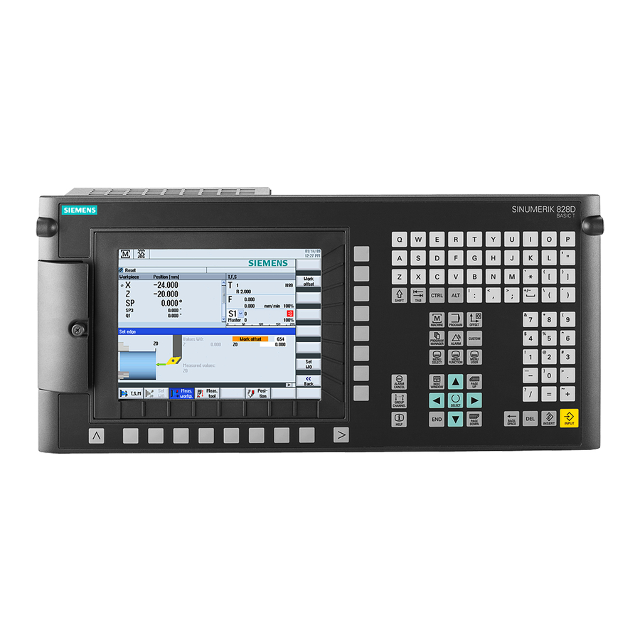
Page 14: System Versions
System description 2.2 System versions System versions Front panel of the different versions with interfaces ① Protective cover for user interfaces ② Menu back key ③ Alphabetic key group ④ Control key group ⑤ Hotkey group ⑥ Cursor key group Hardware and Software Service Manual, 03/2010, 6FC5397-5DP20-0BA0... - Page 15 System description 2.2 System versions ⑦ Numerical block ⑧ Menu forward key ⑨ 3/8" threads for additional components ⑩ Protective cover for user interfaces ⑪ X127: Ethernet (service socket) ⑫ Status LEDs: RDY, NC, CF ⑬ X125: USB port ⑭ Slot for CompactFlash Card with user data Figure 2-2 System versions...
- Page 16 System description 2.2 System versions Hardware and Software Service Manual, 03/2010, 6FC5397-5DP20-0BA0...
-
Page 17: Service Cases - Software
The following software tools should be used for the subsequently described service activities and to backup system and user data: ● Toolbox CD V2.6 SINUMERIK 828D with the following contents: – PLC Programming Tool for Integrated PLC – Commissioning software for SINAMICS S120 –... -
Page 18: Backing Up User Data
Service cases - software 3.1 Backing up user data Backing up user data 3.1.1 This is how you backup user data Application A backup of the data in the complete memory is generated with the "Save data" function. This data backup must be performed for every control that has been commissioned in order to be able to quickly restore the control system in the case of data loss. - Page 19 Service cases - software 3.1 Backing up user data 4. This is followed by the "Query" to backup data: Hardware and Software Service Manual, 03/2010, 6FC5397-5DP20-0BA0...
- Page 20 Service cases - software 3.1 Backing up user data 5. Press the "OK" softkey to backup the data. – A progress indicator indicate the status of the data backup. – After the data backup has been successfully completed, the following message is output: 6.
-
Page 21: This Is How You Load The User Data Backup
Service cases - software 3.1 Backing up user data 3.1.2 This is how you load the user data backup NOTICE If this function is activated, the actual system data is replaced by the data backup. Procedure Proceed as follows to load the internal data backup: 1. - Page 22 Service cases - software 3.1 Backing up user data 3. Using the arrow key, select the menu item "Reload saved user data". 4. Confirm that the backup is loaded by pressing the key <INPUT>. 5. Confirm the confirmation prompt by pressing the <INPUT> key. Are you sure you want to reload saved user data?"...
-
Page 23: Series Commissioning
Service cases - software 3.2 Series commissioning Series commissioning Overview A series commissioning archive is used to completely backup all of the data required for the machine function. A series commissioning archive can be generated on an external data carrier, e.g. USB- FlashDrive or CompactFlash Card at the front panel of the control as well as on the system CompactFlash Card. - Page 24 Easy Archive Select all of the components, unless it is known that individual components do not deviate from the Siemens standard. Select all data classes, unless only certain data (e.g. INDIVIDUAL) are to be backed 6. Press the "Generate archive" softkey.
- Page 25 Service cases - software 3.2 Series commissioning 8. Select a directory. Example: User CF - OR - 9. Press the "New directory" softkey to generate a new directory. The "New Directory" window opens. 10. Enter the required name and confirm with "OK." The directory is created subordinate to the selected folder.
-
Page 26: This Is How You Import A Series Commissioning Archive From An External Data Carrier
Service cases - software 3.2 Series commissioning 3.2.2 This is how you import a series commissioning archive from an external data carrier Reading in an archive from an external data carrier Procedure: 1. Select the "Start-up" operating area. 2. Press the menu forward key. 3. - Page 27 Service cases - software 3.2 Series commissioning 7. Select the required commissioning archive (ARD). Example: User CF 8. Press "OK". A query is displayed, here you can see the most important data of the selected archive to be certain that it is OK. 9.
-
Page 28: This Is How You Generate A Series Commissioning Archive On The System Compactflash Card
Service cases - software 3.2 Series commissioning 3.2.3 This is how you generate a series commissioning archive on the system CompactFlash Card Generating an archive on the system CompactFlash Card Procedure: 1. Select the "Start-up" operating area. 2. Press the menu forward key. 3. -
Page 29: This Is How You Import A Series Commissioning Archive From The System Compactflash Card
Easy Archive Select all of the components, unless it is known that individual components do not deviate from the Siemens standard. Select all data classes, unless only certain data (e.g. INDIVIDUAL) are to be backed 6. Press the "Generate archive" softkey. - Page 30 Service cases - software 3.2 Series commissioning 3.2.4 This is how you import a series commissioning archive from the system CompactFlash Card Reading in an archive from the system CompactFlash Card A description is provided here how you read in a series commissioning archive in order to be able to restore the previous state of the machine.
- Page 31 Service cases - software 3.2 Series commissioning 7. Select the required commissioning archive (ARD). Example: "Archives" → "Manufacturer" 8. Press "OK". A window with the data of the selected archive is displayed. 9. Data is read in when pressing "OK". 10.
-
Page 32: Software Backup
Service cases - software 3.3 Software backup Software backup 3.3.1 This is how you generate a software backup Overview With "Create software backup", a function is provided to generate a backup of the system software including all of the user data saved on the system card. This backup represents the "Backup"... - Page 33 Service cases - software 3.3 Software backup 7. The Startup menu is displayed: 8. Using the cursor keys, select the menu item "Create software backup". 9. Press the <INPUT> key to confirm your selection: 10. Insert a storage medium into the slot on the front panel. Hardware and Software Service Manual, 03/2010, 6FC5397-5DP20-0BA0...
- Page 34 Service cases - software 3.3 Software backup 11. Press the <INPUT> key to start the backup. The software first checks whether a backup was already generated on the card and outputs a message. The backup can now be overwritten or the process interrupted by making the appropriate operator action.
- Page 35 Service cases - software 3.3 Software backup 14. Withdraw the storage medium from the slot at the front panel of the control. 15. Switch the control off. 16. Switch the control on. 17. The control boots normally. Note Note that when the system software is transferred, no license key for the software of the CNC options is transferred.
-
Page 36: This Is How You Install A Software Backup
Service cases - software 3.3 Software backup 3.3.2 This is how you install a software backup Overview A backup previously generated is loaded into the control using the function "Install software update/backup". All system and user data are overwritten with the software backup image. Note Licenses The backup does not contain a license key;... - Page 37 Service cases - software 3.3 Software backup 4. The Startup menu is displayed: 5. Using the cursor keys, select the menu item "Install software update/backup". 6. Press the <INPUT> key to confirm your selection: 7. Insert the storage medium with the backup in the slot and confirm with "Yes" by using the cursor keys to make the selection: Hardware and Software Service Manual, 03/2010, 6FC5397-5DP20-0BA0...
- Page 38 Service cases - software 3.3 Software backup 8. Select the valid backup using the cursor keys. 9. Press the <Input> key to confirm your selection. 10. The following message briefly appears: " " Starting software update Then the screen goes dark for several seconds. 11.
- Page 39 Service cases - software 3.3 Software backup Note If the procedure is interrupted, then it must be restarted. If the system CompactFlash Card is no longer identified as a bootable CompactFlash Card, then a mini boot system must be generated on this card. (See also: This is how you generate a mini boot system (Page 44) ) In this case, the license key of the system CompactFlash Card should be transferred to the control.
-
Page 40: Software Update
Service cases - software 3.4 Software update Software update 3.4.1 This is how you update the software Data backup If a system update is necessary, then the system data must be backed up so that no data is lost in the case of a problem. In this case, we recommend to perform two types of data backup. - Page 41 Service cases - software 3.4 Software update 2. Press the <SELECT> key, "Normal startup" is the default setting. 3. Now press the following keys in succession: Menu reset key, HSK2 (horizontal SK2), VSK2 (vertical SK2) 4. The setup menu is displayed: 5.
- Page 42 Service cases - software 3.4 Software update 7. Use the cursor keys to select "Yes". 8. Select the update image (*.tgz) on the storage medium and confirm with <INPUT>. Hardware and Software Service Manual, 03/2010, 6FC5397-5DP20-0BA0...
- Page 43 Service cases - software 3.4 Software update 9. The software update is started: The following message appears while the update is running: 10. Wait until the following message is output: 11. Withdraw the storage medium from the slot. 12. Switch the control off. 13.
-
Page 44: Mini Boot System On The Compactflash Card
CompactFlash Card as it is without any additional preparation. Mini boot system image "Configuration data" are supplied on the toolbox CD of the SINUMERIK 828D, which include in the scope of delivery of mini boot system image: Figure 3-2... - Page 45 Service cases - software 3.5 Mini boot system on the CompactFlash Card Precondition to write: ● RCS Commander has been installed. ● SW package: Configuration data from the Toolbox has been installed. ● CompactFlash card is a replacement card. Installing the boot system on an empty card Procedure: 1.
- Page 46 Service cases - software 3.5 Mini boot system on the CompactFlash Card 6. If several versions of the toolbox are installed on the PC, you obtain the following selection: 7. All of the identified interchangeable drives are displayed, here in the example, the CompactFlash Card is identified as drive F:\.
- Page 47 Service cases - software 3.5 Mini boot system on the CompactFlash Card 8. Confirm the selection of the target drive with "OK". By pressing the "Write" button, the image is transferred to the target drive. NOTICE While the data is being transferred, do not switch-off the PC and do not remove the CompactFlash Card.
-
Page 48: This Is How You Install A Software Backup Using The Mini Boot System
Service cases - software 3.5 Mini boot system on the CompactFlash Card 3.5.2 This is how you install a software backup using the mini boot system Overview If a CompactFlash Card with a mini boot system is used as system CompactFlash Card, the system software or a previously generated software backup must still be transferred. - Page 49 Service cases - software 3.5 Mini boot system on the CompactFlash Card 3. Confirm the question with "Yes". 4. Insert the CompactFlash Card or a USB-FlashDrive with the image into the slot on the front panel of the control. 5. Confirm the selection with the <INPUT> key. 6.
- Page 50 Service cases - software 3.5 Mini boot system on the CompactFlash Card 7. If a valid image has been found, the following message is output: 8. Wait until the following message is displayed: 9. Switch the control off. 10. Switch the control system back on again: The control boots normally. Note If the system was booted using a mini boot system, there is no valid license key on the system CompactFlash Card.
-
Page 51: Licensing
Access level 1 (password: Manufacturer). Licensing CNC options If an additional CNC option is to be activated at a SINUMERIK 828D, then this CNC option must be licensed at the machine and is only valid for this CompactFlash Card. Hardware and Software... - Page 52 Service cases - software 3.6 Licensing Proceed as follows to access the "licenses" dialog box: 1. Select the "Start-up" operating area. 2. Press the menu forward key. 3. Press the "Licenses" softkey. The "Licensing" window opens. Using the vertical softkeys, you can execute the following actions: –...
-
Page 53: How To Determine The License Requirement
To conclude the assignment, the license key must be entered at the control via the user interface. See also The license database administered by Siemens can only be accessed using the Web License Manager (http://www.siemens.com/automation/license). NOTICE The NC start function is suppressed if a CNC option, for which no valid license key has been entered, is additionally activated. -
Page 54: This Is How You Generated A New License Key
Service cases - software 3.6 Licensing 3. Press the "Missing licenses" softkey to display all options that are activated but not licensed. In the "Set" column, you can deselect the options that you do not require. Figure 3-4 Licensing (example) 4. - Page 55 3. Press the "Licenses" softkey. 4. Press the "Overview" softkey and note down the serial number of the system CompactFlash Card. 5. At your PG/PC, establish a connection to the Web License Manager (http://www.siemens.com/automation/license) Hardware and Software Service Manual, 03/2010, 6FC5397-5DP20-0BA0...
- Page 56 Service cases - software 3.6 Licensing 6. Log on via "Direct access". Follow additional instructions in the Web License Manager: 7. After completing the assignment process, enter the license key displayed in the Web License Manager into the "Licensing" dialog box in SINUMERIK Operate. Note License key via e-mail If you have an e-mail address, you have the option (checkbox) of receiving the license...
-
Page 57: This Is How You Display The Actual License Key
Service cases - software 3.6 Licensing 3. Press the "Licenses" softkey. 4. Press the "Overview” softkey. If you receive the license key via the Web License Manager, enter the license key manually in the field "You can enter a new license key here". 5. - Page 58 Service cases - software 3.6 Licensing Displaying the actual license key in the Internet In order to view the actual license key of the control, using the serial number, it is possible display the license key via the Internet. The serial number is on the system CompactFlash Card - or can be displayed at the control as described above.
- Page 59 Service cases - software 3.6 Licensing 4. In the menu, select "Hardware serial number" and enter the serial number of the system CompactFlash Card. 5. Press the "Display license key" softkey. 6. The actual license key is displayed as follows: Hardware and Software Service Manual, 03/2010, 6FC5397-5DP20-0BA0...
-
Page 60: Enter The Final End User Data (Euna)
Service cases - software 3.7 Enter the final end user data (EUNA) Enter the final end user data (EUNA) Precondition At least access level 3 must be set to change the end user final destination data (EUNA). Repair and Service Contract (RSC) SINUMERIK offers an electronic logbook in which all of the activities relating to the Repair and Service Contract (RSC) are saved. - Page 61 Service cases - software 3.7 Enter the final end user data (EUNA) The data associated with the machine are displayed in the "Machine logbook". 4. Press the "Change" softkey to open the "Machine identity" dialog box. 5. Select the vertical softkey and enter the contact data of: Manufacturer, dealer and end customer.
-
Page 62: This Is How You Make A New Entry In The Logbook
Service cases - software 3.7 Enter the final end user data (EUNA) 3.7.2 This is how you make a new entry in the logbook Generating a new logbook entry In order to log service and diagnostic procedures at the machine, make an entry in the machine logbook. - Page 63 Service cases - software 3.7 Enter the final end user data (EUNA) 4. Press the "New entry" softkey in order to make an entry in the logbook. Complete the fields for the new logbook entry: Figure 3-5 Editing the logbook 5.
-
Page 64: This Is How You Save The Machine Identity
Service cases - software 3.7 Enter the final end user data (EUNA) 3.7.3 This is how you save the machine identity Saving the machine identity Note Ensure that the machine identity that has been entered is correct before saving in order that no incorrect information is saved. - Page 65 Service cases - software 3.7 Enter the final end user data (EUNA) 4. Press the "OK" softkey. The data are pre-assigned so that a change is not necessary. Figure 3-6 The "Name" text field is pre-assigned as follows: <Machine name/Number>+<Number of the CompactFlash Card> You now have the opportunity of changing this name.
-
Page 66: This Is How You Send The End User Final Destination Data
● The PC/PG is connected with the Internet. Please proceed as follows: 1. Open the Internet Browser on your PC/PG. 2. Connection with EUNA (http://www.siemens.com/sinumerik/register). 3. Select a language and enter an e-mail address: Hardware and Software Service Manual, 03/2010, 6FC5397-5DP20-0BA0... - Page 67 9. If no other files are to be uploaded, press the softkey "continue >". 10. Complete the upload by pressing the "Save" softkey. Note Contact persons worldwide If it was not possible to transfer the file, then please contact your local Siemens officeContact (http://www.automation.siemens.com/partner) in sales. Hardware and Software Service Manual, 03/2010, 6FC5397-5DP20-0BA0...
- Page 68 Service cases - software 3.7 Enter the final end user data (EUNA) Hardware and Software Service Manual, 03/2010, 6FC5397-5DP20-0BA0...
-
Page 69: Service Cases - Hardware
Service cases - hardware Overview The sequence in the chapter of the hardware components corresponds to the following criteria: ● Components at the machine ● Components in the control cabinet Component overview Figure 4-1 Components in the control cabinet Note A special tool is supplied to unlock the DC link covers of SINAMICS components. - Page 70 Service cases - hardware Using the unlocking tool An unlocking tool is supplied with every power unit for the purpose of opening the DC link covers. The diagrams below illustrate how the tool should be used. Hardware and Software Service Manual, 03/2010, 6FC5397-5DP20-0BA0...
-
Page 71: Ppu26X/Ppu28X
Service cases - hardware 4.1 PPU26x/PPU28x PPU26x/PPU28x 4.1.1 Status displays at the PPU LED status at the front Figure 4-2 Vertical flap (detail) The 3 LEDs located behind the protective flap on the front side of the PPU mean the following: Name Color... - Page 72 Service cases - hardware 4.1 PPU26x/PPU28x The RJ45 socket is equipped with one green and one yellow LED. As a consequence, the following information of the PLC I/O interface is displayed based on PROFINET: Name Color State Meaning Link Green 100 MBit link available Missing or faulty link Activity...
-
Page 73: This Is How You Remove The Ppu
SYNC *) Green Task system of the SINUMERIK 828D is not synchronized to the send clock of the PLC I/O interface based on PROFINET IO. An internal substitute clock of the same size as the send clock will be generated. -
Page 74: This Is How You Install The Ppu
Service cases - hardware 4.1 PPU26x/PPU28x 8. Withdraw the handwheel terminal X142. 9. Withdraw the RS232 cable, X140. 10. Withdraw the USB cable, X135. 11. Withdraw the connected DRIVE-CLiQ cable X100 – X102 12. Withdraw the connected Ethernet cable X130 13. - Page 75 Service cases - hardware 4.1 PPU26x/PPU28x Note Changing the MAC address When replacing the PPU, then the MAC address of Ethernet interface X130 changes: Notify the customer or the system administrator of the new MAC address. CAUTION Ensure that all of the connectors and screws are correctly tightened or latched and inserted.
-
Page 76: Replacing The System Compactflash Card
Service cases - hardware 4.2 Replacing the system CompactFlash Card Replacing the system CompactFlash Card 4.2.1 This is how you remove the system CompactFlash Card Overview If service is required, it may be necessary to replace the system CompactFlash Card of the control. - Page 77 Service cases - hardware 4.2 Replacing the system CompactFlash Card 3. Move the metal cover to the side and remove it. 4. Remove the system CompactFlash Card from the side. 5. Fix the metal cover by first locating at the rear and then tilting it into the end position. Hardware and Software Service Manual, 03/2010, 6FC5397-5DP20-0BA0...
-
Page 78: This Is How You Insert The System Compactflash Card
Service cases - hardware 4.2 Replacing the system CompactFlash Card 6. Fix the metal cover to the housing using the screw. Note When removing the system CompactFlash Card, carefully ensure that neither the screw nor the system CompactFlash Card falls into the PPU or the machine. PPU as replacement part Note For a PPU as replacement part (spare part), a system CompactFlash Card is not supplied. - Page 79 Service cases - hardware 4.2 Replacing the system CompactFlash Card Inserting the system CompactFlash Card Procedure: 1. Release the screw (M3). 2. Move the metal cover to the side and withdraw it. 3. Gently insert the system CompactFlash Card into the slot until it clicks into place. Hardware and Software Service Manual, 03/2010, 6FC5397-5DP20-0BA0...
- Page 80 Service cases - hardware 4.2 Replacing the system CompactFlash Card 4. Reattach the metal cover by first locating it at the rear and then tilting it into the end position. 5. Fix the metal cover to the housing using the screw. Note When inserting the system CompactFlash Card, carefully ensure that neither the screw nor the system CompactFlash Card falls into the PPU or the machine.
-
Page 81: Sinaut Modem
Service cases - hardware 4.3 SINAUT modem SINAUT modem 4.3.1 LED status displays Validity This description is valid for the GPRS/GSM modem MD720-3, hardware version 3.x. You can find additional information in the System Manual SINAUT MD720-3 in the Chapter "Service functions". -
Page 82: This Is How You Insert The Sim Card
Service cases - hardware 4.3 SINAUT modem 4.3.2 This is how you insert the SIM card CAUTION Risk of damage to sensitive components due to static electricity This activity must always be carried out by trained personnel. Open the module Proceed as follows to open the module: 1. - Page 83 Service cases - hardware 4.3 SINAUT modem 2. Remove the rear section of the housing. 3. The SIM card holder can be seen on the printed circuit board: ① SIM card holder Hardware and Software Service Manual, 03/2010, 6FC5397-5DP20-0BA0...
- Page 84 Service cases - hardware 4.3 SINAUT modem Inserting the SIM card NOTICE When handling SIM cards, carefully observe its safety instructions. When changing the SIM card, do not forget to change the PIN in your control. If you are using a lot of SIM cards, it may make sense to set all SIM cards, e.g. with one cellular phone to the same PIN.
- Page 85 Service cases - hardware 4.3 SINAUT modem The slot for the SIM card in the upper section is shown in white in the following diagram: 3. Insert the SIM card into the upper section of the SIM card holder so that the contact surface is at the bottom and the sloped corner of the SIM card points towards the front of the device.
- Page 86 Service cases - hardware 4.3 SINAUT modem 5. Press the upper section of the SIM card holder downwards. Ensure that the sloped corner of the SIM card clicks into place. 6. Using your fingernail or a suitable object, slide the upper section of the SIM card holder approximately 2 mm in the direction of the arrow to the right in order to lock the SIM card holder.
- Page 87 Service cases - hardware 4.3 SINAUT modem 8. Then assemble the two housing sections again. To do this, locate the printed circuit board in the upper and lower rails inside the rear section of the housing. ① Rail for the printed circuit board 9.
-
Page 88: This Is How You Load The Factory Settings
Service cases - hardware 4.3 SINAUT modem 4.3.3 This is how you load the factory settings Loading the factory settings Figure 4-5 MD720-3: Front view If you press the SET key for longer than 4 seconds until the LED "C" starts to light up, then the SINAUT MD720-3 configuration is reset to the default values set in the factory. -
Page 89: Machine Control Panels
Service cases - hardware 4.4 Machine control panels Machine control panels 4.4.1 Status displays MCP 310C PN LEDs for status display For the MCP 310C PN there are 3 LEDs in a row (H1-H3), which provide information about the module state: Figure 4-7 Status displays H1 (green) -
Page 90: This Is How You Remove The Mcp 310C Pn
Service cases - hardware 4.4 Machine control panels 4.4.2 This is how you remove the MCP 310C PN Overview The activities that must be taken into account when replacing a machine control panel are subsequently described. If the machine control panel has a hardware defect, then it must be replaced by an identical replacement part. - Page 91 Slot for Emergency Stop button or spindle override ② Power supply interface ③ Handwheel connection *) ④ Handwheel connection *) ⑤ Switch: for SINUMERIK 828D, no function ⑥ Switch ⑦ LEDs ⑧ Ethernet cable strain relief ⑨ Port 2: PLC I/O interfaces based on PROFINET ⑩...
-
Page 92: This Is How You Install The Mcp 310C Pn
Service cases - hardware 4.4 Machine control panels Procedure: 1. Switch-off the control: Completely switch off the system. Check that the system is in a no- voltage condition and is locked-out so that it cannot be switched on again without the appropriate authorization. -
Page 93: Status Displays, Mcp 483C Pn
Switch S2 Switch S2 defines the IP address of the machine control panel: Device name mcp-pn64 For SINUMERIK 828D, the IP address = 192.168.214.64 must always be assigned to the MCP. 4.4.4 Status displays, MCP 483C PN LED status displays... -
Page 94: This Is How You Remove The Mcp 483C Pn
Service cases - hardware 4.4 Machine control panels H1 (green) H2 (green) H3 (red) PowerOK PN Sync PN Fault Power Off Power On (voltage is stable) Boot software runs and loads the system software. System software runs. System software runs, no communication to the controller. - Page 95 ⑨ Ethernet cable strain relief ⑩ LEDs ⑪ Switch ⑫ Switch: for SINUMERIK 828D, has no function ⑬ Handwheel connection *) Handwheel connection *) ⑭ Power supply interface Handwheels are directly connected to the PPU: Do not wire X60/X61 Figure 4-11...
-
Page 96: This Is How You Install The Mcp 483C Pn
Service cases - hardware 4.4 Machine control panels Procedure: 1. Switch-off the control: Completely switch off the system. Check that the system is in a no- voltage condition and is locked-out so that it cannot be switched on again without the appropriate authorization. - Page 97 Figure 4-12 Switch S2 Switch S2 defines the IP address of the machine control panel: Device name mcp-pn64 For SINUMERIK 828D, the IP address = 192.168.214.64 must always be assigned to the MCP. Hardware and Software Service Manual, 03/2010, 6FC5397-5DP20-0BA0...
-
Page 98: I/O Modules
Service cases - hardware 4.5 I/O modules I/O modules 4.5.1 Status displays PP 72/48D PN LEDs for status display The following LEDs on the I/O module provide information about the module state: Figure 4-13 Switch S1 and LEDs H1 to H6 H1 (green) H2 (green) H3 (red) -
Page 99: This Is How You Remove The Pp 72/48D Pn
Service cases - hardware 4.5 I/O modules LEDs at port 1 and port 2 There are 2 LEDs at port 1 and port 2 for diagnostics of the PLC I/O interfaces based on PROFINET. Figure 4-14 Port 1 and port 2 LED for communication at the RJ45 connector. - Page 100 Service cases - hardware 4.5 I/O modules Removing Figure 4-15 Rear of the PP 72/48D PN NOTICE Electro-static discharge (ESD) Before you touch the module, discharge yourself at the cabinet or at the ground terminal. Procedure: 1. Switch-off the control: Completely switch off the system. Check that the system is in a no- voltage condition and is locked-out so that it cannot be switched on again without the appropriate authorization.
-
Page 101: This Is How You Install The Pp 72/48D Pn
Service cases - hardware 4.5 I/O modules 8. Remove the communication cables from interface X2 (port 1 and port 2). 9. Remove the ground connection by releasing the grounding screw. 10. To remove the I/O module, release the fixing screws. 11. -
Page 102: Status Displays Pp 72/48D 2/2A Pn
Service cases - hardware 4.5 I/O modules 4.5.4 Status displays PP 72/48D 2/2A PN LEDs for status display The following LEDs on the I/O module provide information about the module state: Figure 4-16 Switch S1 and LEDs H1 to H6 H1 (green) H2 (green) H3 (red) -
Page 103: This Is How You Remove The Pp 72/48D 2/2A Pn
Service cases - hardware 4.5 I/O modules LEDs at port 1 and port 2 There are 2 LEDs at port 1 and port 2 for diagnostics of the PLC I/O interfaces based on PROFINET. Figure 4-17 Port 1 and port 2 LED for communication at the RJ45 connector. - Page 104 Service cases - hardware 4.5 I/O modules Removing Figure 4-18 Rear of PP 72/48D 2/2A PN NOTICE Electro-static discharge (ESD) Before you touch the module, discharge yourself at the cabinet or at the ground terminal. Procedure: 1. Switch-off the control: Completely switch off the system. Check that the system is in a no- voltage condition and is locked-out so that it cannot be switched on again without the appropriate authorization.
-
Page 105: This Is How You Install The Pp 72/48D 2/2A Pn
Service cases - hardware 4.5 I/O modules 8. Remove the communication cables from interface X2 (port 1 and port 2). 9. Remove the ground connection by releasing the grounding screw. 10. To remove the I/O module, release the fixing screws. 11. -
Page 106: Expansion Module Nx10
Service cases - hardware 4.6 Expansion module NX10 Expansion module NX10 4.6.1 Status displays on the NX10 LEDs for status display The following LEDs on the NX10 provide information about the module state: Color State Description RDY, H1 Electronics power supply outside the permissible tolerance range. Green Continuous light Component is ready. - Page 107 Service cases - hardware 4.6 Expansion module NX10 Removing Figure 4-19 NX10 illustration NOTICE Electro-static discharge (ESD) Before you touch the component, discharge yourself at the cabinet or at the ground terminal. Hardware and Software Service Manual, 03/2010, 6FC5397-5DP20-0BA0...
-
Page 108: This Is How You Install The Nx10
Service cases - hardware 4.6 Expansion module NX10 Procedure: 1. Switch-off the control: Completely switch off the system. Check that the system is in a no- voltage condition and is locked-out so that it cannot be switched on again without the appropriate authorization. -
Page 109: Single Motor Modules
Service cases - hardware 4.7 Single Motor Modules Single Motor Modules 4.7.1 SMM status displays Status displays The Motor Module has the following status displays, which provide information about the module state: LED state Description, cause Remedy Ready (H200) DC Link (H201) The electronics power supply is missing or outside the –... -
Page 110: Smm Connections
Service cases - hardware 4.7 Single Motor Modules 4.7.2 SMM connections Connections Figure 4-20 Single Motor Module (SMM) Hardware and Software Service Manual, 03/2010, 6FC5397-5DP20-0BA0... -
Page 111: This Is How You Remove A Motor Module
Service cases - hardware 4.7 Single Motor Modules 4.7.3 This is how you remove a Motor Module Overview The activities required when replacing a Motor Module are subsequently described. If a Motor Module has a hardware defect, then it must be replaced by an identical module. Preconditions: ●... - Page 112 Service cases - hardware 4.7 Single Motor Modules 9. Using a multimeter (set the measuring range to 1000 V DC) at the points DCP/DCN, check that the DC link voltage is in a no-voltage condition. Only continue with the work when it has been absolutely ensured that no voltage is present (a no-voltage condition has been established).
-
Page 113: This Is How You Install A Motor Module
Service cases - hardware 4.7 Single Motor Modules 13. Release the screws that are used to retain the motor module to the mounting plate. 14. Remove the protective conductor connection of the Motor Module. 15. Remove the Motor Module from the control cabinet. 4.7.4 This is how you install a Motor Module Installing... - Page 114 Service cases - hardware 4.7 Single Motor Modules 5. Tighten the Torx screws of the DC link busbars, observe the correct sequence. 6. Place the red jumper plug on the electronics busbar until it clicks into place. 7. Place the 24 V terminal adapter on the electronics power supply busbar until it clicks into place.
-
Page 115: Double Motor Modules
Service cases - hardware 4.8 Double Motor Modules Double Motor Modules 4.8.1 DMM status displays Status displays The Motor Module has the following status displays, which provide information about the module state: LED state Description, cause Remedy Ready (H200) DC Link (H201) The electronics power supply is missing or outside the –... -
Page 116: Dmm Connections
Service cases - hardware 4.8 Double Motor Modules 4.8.2 DMM connections Connections Figure 4-21 Double Motor Module (DMM) Hardware and Software Service Manual, 03/2010, 6FC5397-5DP20-0BA0... -
Page 117: This Is How You Remove A Motor Module
Service cases - hardware 4.8 Double Motor Modules 4.8.3 This is how you remove a Motor Module Overview The activities required when replacing a Motor Module are subsequently described. If a Motor Module has a hardware defect, then it must be replaced by an identical module. Preconditions: ●... - Page 118 Service cases - hardware 4.8 Double Motor Modules 9. Using a multimeter (set the measuring range to 1000 V DC) at the points DCP/DCN, check that the DC link voltage is in a no-voltage condition. Only continue with the work when it has been absolutely ensured that no voltage is present (a no-voltage condition has been established).
-
Page 119: This Is How You Install A Motor Module
Service cases - hardware 4.8 Double Motor Modules 13. Release the screws that are used to retain the motor module to the mounting plate. 14. Remove the protective conductor connection of the Motor Module. 15. Remove the Motor Module from the control cabinet. 4.8.4 This is how you install a Motor Module Installing... - Page 120 Service cases - hardware 4.8 Double Motor Modules 5. Tighten the Torx screws of the DC link busbars, observe the correct sequence. 6. Place the red jumper plug on the electronics busbar until it clicks into place. 7. Place the 24 V terminal adapter on the electronics power supply busbar until it clicks into place.
-
Page 121: Smart Line Modules
Service cases - hardware 4.9 Smart Line Modules Smart Line Modules 4.9.1 SLM (< 16 kW) status displays Status displays The 5 kW and 10 kW Smart Line Modules have the following status displays, which provide information about the module state: Color State Description, cause... -
Page 122: Slm (< 16 Kw) Connections
Service cases - hardware 4.9 Smart Line Modules 4.9.2 SLM (< 16 kW) connections Connections Figure 4-22 SLM connections Hardware and Software Service Manual, 03/2010, 6FC5397-5DP20-0BA0... -
Page 123: Slm (16 Kw And Higher) Status Displays
Service cases - hardware 4.9 Smart Line Modules 4.9.3 SLM (16 kW and higher) status displays Status displays The Smart Line Modules ≥ 16 kW have the following status displays, which provide information about the module state: LED state Description, cause Remedy Ready (H200) DC Link (H201) -
Page 124: Slm (16 Kw And Higher) Connections
Service cases - hardware 4.9 Smart Line Modules 4.9.4 SLM (16 kW and higher) connections Connections Figure 4-23 Connections,SLM ≥ 16 kW Hardware and Software Service Manual, 03/2010, 6FC5397-5DP20-0BA0... -
Page 125: This Is How You Remove An Slm
Service cases - hardware 4.9 Smart Line Modules 4.9.5 This is how you remove an SLM Overview The activities that must be taken into account when replacing a Smart Line Module (SLM) are subsequently described. If a module has a hardware defect, then it must be replaced by an identical module. Preconditions: ●... - Page 126 Service cases - hardware 4.9 Smart Line Modules 9. Using a multimeter (set the measuring range to 1000 V DC) at the points DCP/DCN, check that the DC link voltage is in a no-voltage condition. Only continue with the work when it has been absolutely ensured that no voltage is present (no-voltage condition has been established).
-
Page 127: This Is How You Install An Slm
Service cases - hardware 4.9 Smart Line Modules 4.9.6 This is how you install an SLM Installing DANGER Risk of electric shock A hazardous voltage is present for up to 5 minutes after the power supply has been switched off. The protective cover must not be opened until this time has elapsed. The warning information on the components must be carefully observed! Procedure: 1. - Page 128 Service cases - hardware 4.9 Smart Line Modules 9. Reconnect the line supply connection X1 at the module. 10. Insert the DRIVE-CLiQ cables that were previously withdrawn into sockets X200 - X202. 11. Reinsert the enable terminals X21 at the module. 12.
-
Page 129: Active Line Modules
Service cases - hardware 4.10 Active Line Modules 4.10 Active Line Modules 4.10.1 ALM status displays Status displays The Active Line Module (ALM) has the following status displays, which provide information about the module status: LED state Description, cause Remedy Ready (H200) DC Link (H201) Electronics power supply is missing or outside... -
Page 130: Alm Connections
Service cases - hardware 4.10 Active Line Modules 4.10.2 ALM connections Connections Figure 4-24 ALM connections Hardware and Software Service Manual, 03/2010, 6FC5397-5DP20-0BA0... -
Page 131: This Is How You Remove An Alm
Service cases - hardware 4.10 Active Line Modules 4.10.3 This is how you remove an ALM Overview The activities that must be taken into account when replacing an Active Line Module (ALM) are subsequently described. If a module has a hardware defect, then it must be replaced by an identical module. Preconditions: ●... - Page 132 Service cases - hardware 4.10 Active Line Modules 9. Using a multimeter (set the measuring range to 1000 V DC) at the points DCP/DCN, check that the DC link voltage is in a no-voltage condition. Only continue with the work when it has been absolutely ensured that no voltage is present (no-voltage condition has been established).
-
Page 133: This Is How You Install An Alm
Service cases - hardware 4.10 Active Line Modules 4.10.4 This is how you install an ALM Installing DANGER Risk of electric shock A hazardous voltage is present for up to 5 minutes after the power supply has been switched off. The protective cover must not be opened until this time has elapsed. The warning information on the components must be carefully observed! Procedure: 1. - Page 134 Service cases - hardware 4.10 Active Line Modules 9. Reconnect the line supply connection X1 at the module. 10. Insert the DRIVE-CLiQ cables that were previously withdrawn into sockets X200 - X202. 11. Reinsert the enable terminals X21 at the module. 12.
-
Page 135: Smc20 / Smc30
Service cases - hardware 4.11 SMC20 / SMC30 4.11 SMC20 / SMC30 4.11.1 SMC20 status displays Status displays The Sensor Module Cabinet-Mounted SMC20 has the following status displays, which provide information about the module state: Color State Description, cause Remedy Electronics power supply is missing or outside –... -
Page 136: Smc20 Connections
Service cases - hardware 4.11 SMC20 / SMC30 4.11.2 SMC20 connections Connections Figure 4-25 Connections SMC20 4.11.3 This is how you remove an SMC20 Overview The activities that must be taken into account when replacing an SMC20 are subsequently described. If a SMC20 has a hardware defect, then it must be replaced by an identical module. - Page 137 Service cases - hardware 4.11 SMC20 / SMC30 Preconditions: ● The module is defective and must be replaced. ● The control cabinet is in a no-voltage condition, all of the connectors and cables are labeled. Removing Figure 4-26 SMC20 removal NOTICE Electro-static discharge (ESD) Before you touch the module, discharge yourself at the cabinet or at the ground terminal.
-
Page 138: This Is How You Install An Smc20
Service cases - hardware 4.11 SMC20 / SMC30 CAUTION The 50 mm clearances above and below the components must be observed. 4.11.4 This is how you install an SMC20 Installing Procedure: 1. Place the components on the mounting rail. 2. Then, swivel the components on the mounting rail so that the mounting catches click into place at the rear. -
Page 139: Smc30 Status Displays
Service cases - hardware 4.11 SMC20 / SMC30 4.11.5 SMC30 status displays Status displays The Sensor Module Cabinet-Mounted SMC30 has the following status displays, which provide information about the module state: Color State Description, cause Remedy Electronics power supply is missing or outside –... -
Page 140: Smc30 Connections
Service cases - hardware 4.11 SMC20 / SMC30 4.11.6 SMC30 connections Connections Figure 4-27 Connections SMC30 4.11.7 This is how you remove an SMC30 Overview The activities that must be taken into account when replacing an SMC30 are subsequently described. If an SMC30 has a hardware defect, then it must be replaced by an identical module. - Page 141 Service cases - hardware 4.11 SMC20 / SMC30 Preconditions: ● The module is defective and must be replaced. ● The control cabinet is in a no-voltage condition, all of the connectors and cables are labeled. Removing Figure 4-28 SMC30 removal NOTICE Electro-static discharge (ESD) Before you touch the module, discharge yourself at the cabinet or at the ground terminal.
-
Page 142: This Is How You Install An Smc30
Service cases - hardware 4.11 SMC20 / SMC30 4. Slide the lug downwards. 5. Swivel the module to the front to remove it. CAUTION The 50 mm clearances above and below the components must be observed. 4.11.8 This is how you install an SMC30 Installing Figure 4-29 Installing SMC30... - Page 143 Service cases - hardware 4.11 SMC20 / SMC30 3. Slide the components along the mounting rail to either the left or right up to their final position. 4. Screw on the protective conductor connection. 5. Screw on the encoder connecting cable to X520 or X521 / X531, if required, also the shield connection.
-
Page 144: Sme20 / Sme25
Service cases - hardware 4.12 SME20 / SME25 4.12 SME20 / SME25 4.12.1 SME20 connections Connections Figure 4-30 Connections SME20 4.12.2 This is how you remove an SME20 and install it again Overview The activities that must be taken into account when replacing an SME20 are subsequently described. -
Page 145: Sme25 Connections
Service cases - hardware 4.12 SME20 / SME25 Procedure: 1. Release the encoder connecting cable of the SME20. 2. Withdraw the DRIVE-CLiQ cable from the SME20. 3. Release the protective conductor connection of the SME20. 4. Remove the defective SME20. Installing Procedure: 1. -
Page 146: This Is How You Remove An Sme25 And Install It Again
Service cases - hardware 4.12 SME20 / SME25 4.12.4 This is how you remove an SME25 and install it again Overview The activities that must be taken into account when replacing an SME25 are subsequently described. If an SME25 has a hardware defect, then it must be replaced by an identical module. Preconditions: ●... -
Page 147: Dmc20
Service cases - hardware 4.13 DMC20 4.13 DMC20 4.13.1 DMC20 status displays Status displays The DRIVE-CLiQ Hub Module DMC20 has the following status displays, which provide information about the module state: Color State Description, cause Remedy Electronics power supply is missing or outside –... -
Page 148: Dmc20 Connections
Service cases - hardware 4.13 DMC20 4.13.2 DMC20 connections Connections Figure 4-32 Connections DMC20 4.13.3 This is how you remove a DMC20 Overview The activities that must be taken into account when replacing a DMC20 are subsequently described. If a DMC20 has a hardware defect, then it must be replaced by an identical module. Preconditions: ●... - Page 149 Service cases - hardware 4.13 DMC20 Removing Figure 4-33 DMC20 removal NOTICE Electro-static discharge (ESD) Before you touch the module, discharge yourself at the cabinet or at the ground terminal. Procedure: 1. Before withdrawing it, label the connector X524 for the electronics power supply. 2.
-
Page 150: This Is How You Install A Dmc20
Service cases - hardware 4.13 DMC20 4.13.4 This is how you install a DMC20 Installing Procedure: 1. Place the components on the mounting rail. 2. Then, swivel the components on the mounting rail so that the mounting catches click into place at the rear. -
Page 151: Spare Parts And Accessories
Order data for accessories The following accessories are available: Component Order No.: Description CompactFlash Card (empty) 1 GB 6FC5313-5AG00-0AA0 for SIMOTION / SINUMERIK USB FlashDrive 2 GB 6ES7648-0DC40-0AA0 USB2.0, bootable See also Spares-on-web (https://b2b-extern.automation.siemens.com/spares_on_web) Hardware and Software Service Manual, 03/2010, 6FC5397-5DP20-0BA0... - Page 152 Spare parts and accessories Hardware and Software Service Manual, 03/2010, 6FC5397-5DP20-0BA0...
-
Page 153: Esd Guidelines
● Signal cables and load cables must be routed at the greatest possible distance from one another. ● Only use Siemens signal cables for connecting to and from the NC or PLC. ● Signal cables may not be routed close to strong external magnetic fields (e.g. motors and transformers). -
Page 154: Esd Measures
ESD guidelines A.2 ESD measures ESD measures CAUTION The modules contain electrostatically sensitive devices. Discharge yourself of electrostatic energy before touching the electronic modules. The easiest way to do this is to touch a conductive, grounded object immediately beforehand (for example, bare metal parts of control cabinet or the protective ground contact of a socket outlet). -
Page 155: Appendix
Appendix List of abbreviations Abbreviation Meaning Explanation Active Line Module ASCII American Standard Code for Information American coding standard for the exchange of Interchange information AUTO "Automatic" operating mode Mode group BERO Proximity limit switch with feedback oscillator BICO Binector Connector Interconnection technology for the drive Cross Error Compensation Computerized Numerical Control... - Page 156 Appendix B.1 List of abbreviations Abbreviation Meaning Explanation Leadscrew Error Compensation Leadscrew error compensation Light Emitting Diode Light-emitting diode Local User Data Local user data MAIN Main program Main program (OB1, PLC) Megabyte Machine Control Panel Machine control panel Machine Coordinate System Machine data "Manual Data Automatic"...
- Page 157 Appendix B.1 List of abbreviations Abbreviation Meaning Explanation Workpiece Coordinate System Work Offset Zero Offset Active Identifier (file type) for work offset data Hardware and Software Service Manual, 03/2010, 6FC5397-5DP20-0BA0...
- Page 158 Appendix B.1 List of abbreviations Hardware and Software Service Manual, 03/2010, 6FC5397-5DP20-0BA0...
-
Page 159: Feedback On The Documentation
This document will be continuously improved with regard to its quality and ease of use. Please help us with this task by sending your comments and suggestions for improvement via e-mail or fax to: E-mail: mailto:docu.motioncontrol@siemens.com Fax: +49 9131 - 98 2176 Please use the fax form on the back of this page. - Page 160 Appendix B.2 Feedback on the documentation Hardware and Software Service Manual, 03/2010, 6FC5397-5DP20-0BA0...
- Page 161 Appendix B.2 Feedback on the documentation Hardware and Software Service Manual, 03/2010, 6FC5397-5DP20-0BA0...
- Page 162 Appendix B.2 Feedback on the documentation Hardware and Software Service Manual, 03/2010, 6FC5397-5DP20-0BA0...
-
Page 163: Documentation Overview
Appendix B.3 Documentation overview Documentation overview Hardware and Software Service Manual, 03/2010, 6FC5397-5DP20-0BA0... - Page 164 Appendix B.3 Documentation overview Hardware and Software Service Manual, 03/2010, 6FC5397-5DP20-0BA0...
-
Page 165: Index
Index Licenses Save as backup, 57 Licensing a CNC option, 51 Logbook entry, 62 Backing up log files, 17 Mini boot system, 45 CompactFlash Card, 151 Connections ALM, 130 DMC20, 148 DMM, 116 Repair and Service Contract (RSC), 60 SLM ≥ 16kW, 124 RI suppression measures, 153 SLM 5kW, 10kW, 122 Rules for routing cables, 153... - Page 166 Index Hardware and Software Service Manual, 03/2010, 6FC5397-5DP20-0BA0...
- Page 167 Click below to find more Mipaper at www.lcis.com.tw Mipaper at www.lcis.com.tw...