Siemens SINUMERIK 840D sl Operating Manual
Sinumerik universal
Hide thumbs
Also See for SINUMERIK 840D sl:
- Function manual (2184 pages) ,
- Programming manual (1334 pages) ,
- Commissioning manual (1102 pages)
Table of Contents
Advertisement
Quick Links
Universal
SINUMERIK
SINUMERIK 840D sl / 828D
Universal
Operating Manual
Valid for:
Controls
SINUMERIK 840D sl / 840DE sl / 828D
Software
CNC system software
for 840D sl/ 840DE sl
SINUMERIK Operate for PCU/PC
01/2015
6FC5398-6AP40-5BA2
V4.7 SP1
V4.7 SP1
___________________
Preface
___________________
Fundamental safety
instructions
___________________
Introduction
___________________
Setting up the machine
___________________
Working in manual mode
___________________
Machining the workpiece
___________________
Simulating machining
___________________
Creating a G code program
___________________
Multi-channel view (only
840D sl)
___________________
Collision avoidance (only
840D sl)
___________________
Tool management
___________________
Managing programs
___________________
Teaching in a program
___________________
HT 8
___________________
Ctrl-Energy
___________________
Easy Message (828D only)
___________________
Easy Extend (828D only)
___________________
Service Planner (828D only)
___________________
Ladder Viewer and Ladder
add-on (828D only)
___________________
Alarm, error, and system
messages
___________________
Appendix
1
2
3
4
5
6
7
8
9
10
11
12
13
14
15
16
17
18
19
A
Advertisement
Table of Contents

Related Manuals for Siemens SINUMERIK 840D sl


Summary of Contents for Siemens SINUMERIK 840D sl
- Page 1 Service Planner (828D only) Valid for: ___________________ Ladder Viewer and Ladder add-on (828D only) Controls ___________________ SINUMERIK 840D sl / 840DE sl / 828D Alarm, error, and system messages Software ___________________ CNC system software Appendix for 840D sl/ 840DE sl V4.7 SP1...
- Page 2 Note the following: WARNING Siemens products may only be used for the applications described in the catalog and in the relevant technical documentation. If products and components from other manufacturers are used, these must be recommended or approved by Siemens. Proper transport, storage, installation, assembly, commissioning, operation and maintenance are required to ensure that the products operate safely and without any problems.
-
Page 3: Preface
Training For information about the range of training courses, refer under: ● www.siemens.com/sitrain SITRAIN - Siemens training for products, systems and solutions in automation technology ● www.siemens.com/sinutrain SinuTrain - training software for SINUMERIK FAQs You can find Frequently Asked Questions in the Service&Support pages under Product Support. - Page 4 Preface SINUMERIK You can find information on SINUMERIK under the following link: www.siemens.com/sinumerik Target group This documentation is intended for users of universal machines running the SINUMERIK Operate software. Benefits The operating manual helps users familiarize themselves with the control elements and commands.
- Page 5 Table of contents Preface ..............................3 Fundamental safety instructions ......................15 General safety instructions ..................... 15 Industrial security ........................16 Introduction ............................17 Product overview ........................17 Operator panel fronts ......................18 2.2.1 Overview ..........................18 2.2.2 Keys of the operator panel ...................... 19 Machine control panels ......................
- Page 6 Table of contents Settings for the machine ......................69 3.4.1 Switching over the coordinate system (MCS/WCS) .............. 69 3.4.2 Switching the unit of measurement ..................70 3.4.3 Setting the zero offset ......................71 Zero offsets ..........................73 3.5.1 Display active zero offset ....................... 74 3.5.2 Displaying the zero offset "overview"...
- Page 7 Table of contents Repositioning axes ........................ 108 Starting execution at a specific point ..................109 5.7.1 Use block search ........................109 5.7.2 Continuing program from search target ................111 5.7.3 Simple search target definition ..................... 111 5.7.4 Defining an interruption point as search target ..............112 5.7.5 Entering the search target via search pointer ...............
- Page 8 Table of contents 5.16.3.1 General procedure ....................... 156 5.16.3.2 Setting the tolerance ......................157 5.16.3.3 Specifying a reference point ....................157 5.16.3.4 Accepting contours ......................158 Simulating machining ........................... 161 Overview ..........................161 Simulation prior to machining of the workpiece ..............168 Simultaneous recording prior to machining of the workpiece ..........
- Page 9 Table of contents Multi-channel view in the "Machine" operating area ............. 193 Multi-channel view for large operator panels ................ 196 Setting the multi-channel view ....................198 Collision avoidance (only 840D sl) ....................... 201 Activate collision avoidance ....................201 Set collision avoidance ......................203 Tool management ..........................
- Page 10 Table of contents 11.1.3 USB drives ........................... 260 11.1.4 FTP drive ..........................261 11.2 Opening and closing a program ................... 262 11.3 Executing a program ......................264 11.4 Creating a directory/program/job list/program list ..............265 11.4.1 Creating a new directory ...................... 265 11.4.2 Creating a new workpiece ....................
- Page 11 Table of contents 12.4.2 Teach in rapid traverse G0 ....................312 12.4.3 Teach in straight G1 ......................312 12.4.4 Teaching in circle intermediate and circle end point CIP ............313 12.4.5 Teach-in A spline ........................313 12.5 Editing a block ........................315 12.6 Selecting a block ........................
- Page 12 Table of contents 17.2 Set maintenance tasks ......................353 Ladder Viewer and Ladder add-on (828D only) ..................355 18.1 Introduction .......................... 355 18.2 Ladder add-on tool ....................... 355 18.3 Structure of the user interface ....................356 18.4 Control options ........................358 18.5 Displaying PLC properties ....................
- Page 13 Table of contents 19.9 Remote diagnostics ......................397 19.9.1 Setting remote access ......................397 19.9.2 Permit modem ........................399 19.9.3 Request remote diagnostics ....................399 19.9.4 Exit remote diagnostics ......................400 Appendix............................. 401 840D sl documentation overview ..................401 Index..............................403 Universal Operating Manual, 01/2015, 6FC5398-6AP40-5BA2...
- Page 14 Table of contents Universal Operating Manual, 01/2015, 6FC5398-6AP40-5BA2...
-
Page 15: Fundamental Safety Instructions
Fundamental safety instructions General safety instructions WARNING Risk of death if the safety instructions and remaining risks are not carefully observed If the safety instructions and residual risks are not observed in the associated hardware documentation, accidents involving severe injuries or death can occur. •... -
Page 16: Industrial Security
Siemens recommends strongly that you regularly check for product updates. For the secure operation of Siemens products and solutions, it is necessary to take suitable preventive action (e.g. cell protection concept) and integrate each component into a holistic, state-of-the-art industrial security concept. -
Page 17: Introduction
Introduction Product overview The SINUMERIK controller is a CNC (Computerized Numerical Controller) for machine tools. You can use the CNC to implement the following basic functions in conjunction with a machine tool: ● Creation and adaptation of part programs ● Execution of part programs ●... -
Page 18: Operator Panel Fronts
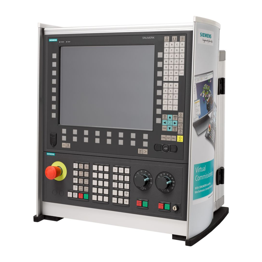
Introduction 2.2 Operator panel fronts Operator panel fronts 2.2.1 Overview Introduction The display (screen) and operation (e.g. hardkeys and softkeys) of the SINUMERIK Operate user interface use the operator panel front. In this example, the OP 010 operator panel front is used to illustrate the components that are available for operating the controller and machine tool. -
Page 19: Keys Of The Operator Panel
A more precise description as well as a view of the other operator panel fronts that can be used may be found in the following reference: Manual operator components and networking; SINUMERIK 840D sl 2.2.2 Keys of the operator panel The following keys and key combinations are available for operation of the control and the machine tool. - Page 20 Introduction 2.2 Operator panel fronts <NEXT WINDOW> • Toggles between the windows. • For a multi-channel view or for a multi-channel functionality, switches within a channel gap between the upper and lower window. • Selects the first entry in selection lists and in selection fields. •...
- Page 21 Introduction 2.2 Operator panel fronts <PAGE DOWN> Scrolls downwards by one page in a window. <PAGE DOWN> + <SHIFT> In the program manager and in the program editor, from the cursor position, selects directories or program blocks up to the end of the window.
- Page 22 Introduction 2.2 Operator panel fronts <Cursor up> • Editing box Moves the cursor into the next upper field. • Navigation – Moves the cursor in a table to the next cell upwards. – Moves the cursor upwards in a menu screen. <Cursor up>...
- Page 23 Introduction 2.2 Operator panel fronts <SELECT> + <SHIFT> Selects in selection lists and in selection boxes the previous entry or the last entry. <END> Moves the cursor to the last entry field in a window, to the end of a table or a program block.
- Page 24 Introduction 2.2 Operator panel fronts <TAB> + <SHIFT> • In the program editor, indents the cursor by one character. • In the program manager, moves the cursor to the next entry to the left. <TAB> + <CTRL> • In the program editor, indents the cursor by one character. •...
- Page 25 Introduction 2.2 Operator panel fronts <CTRL> + <P> Generates a screenshot from the actual user interface and saves it as file. <CTRL> + <S> Switches the single block in or out in the simulation. <CTRL> + <V> • Pastes text from the clipboard at the actual cursor position. •...
- Page 26 Introduction 2.2 Operator panel fronts <SHIFT> + <ALT> + <D> Backs up the log files on the USB-FlashDrive. If a USB-FlashDrive is not inserted, then the files are backed-up in the manufacturer's area of the CF card. <SHIFT> + <ALT> + <T> Starts "HMI Trace".
- Page 27 Introduction 2.2 Operator panel fronts <Minus> • Closes a directory which contains the element. • Reduces the size of the graphic view for simulation and traces. <Equals> Opens the calculator in the entry fields. <Asterisk> Opens a directory with all of the subdirectories. <Tilde>...
- Page 28 Introduction 2.2 Operator panel fronts <OFFSET> - only OP 010 and OP 010C Calls the "Parameter" operating area. <PROGRAM MANAGER> - only OP 010 and OP 010C Calls the "Program Manager" operating area. Menu forward key Advances in the extended horizontal softkey bar. Menu back key Returns to the higher-level menu.
-
Page 29: Machine Control Panels
2.3.1 Overview The machine tool can be equipped with a machine control panel by Siemens or with a specific machine control panel from the machine manufacturer. You use the machine control panel to initiate actions on the machine tool such as traversing an axis or starting the machining of a workpiece. - Page 30 Introduction 2.3 Machine control panels Operator controls Emergency Off button Press the button in situations where: • life is at risk. • there is the danger of a machine or workpiece being damaged. All drives will be stopped with the greatest possible braking torque. Machine manufacturer For additional responses to pressing the Emergency Stop button, please refer to the machine manufacturer's instructions.
- Page 31 Introduction 2.3 Machine control panels Operating modes, machine functions <JOG> Select "JOG" mode. <TEACH IN> Select "Teach In" submode. <MDI> Select "MDI" mode. <AUTO> Select "AUTO" mode. <REPOS> Repositions, re-approaches the contour. <REF POINT> Approach reference point. Inc <VAR>(Incremental Feed Variable) Incremental mode with variable increment size.
- Page 32 Introduction 2.3 Machine control panels Traversing axes with rapid traverse override and coordinate switchover Axis keys Selects an axis. Direction keys Select the traversing direction. <RAPID> Traverse axis in rapid traverse while pressing the direction key. <WCS MCS> Switches between the workpiece coordinate system (WCS) and machine coordinate system (MCS).
-
Page 33: Operator Interface
Introduction 2.4 Operator interface Operator interface 2.4.1 Screen layout Overview Active operating area and mode Alarm/message line Program name Channel state and program control Channel operational messages Axis position display in actual value window Universal Operating Manual, 01/2015, 6FC5398-6AP40-5BA2... -
Page 34: Status Display
Introduction 2.4 Operator interface Display for Active tool T • Current feedrate F • Active spindle with current status (S) • Spindle utilization rate in percent • Name of the active tool carrier with display of a rotation in space and plane •... - Page 35 Display Description The power rating display must be switched on in the status line. Note Information about configuration is available in the following reference: System Manual "Ctrl-Energy", SINUMERIK 840D sl / 828D Active operating area Display Description "Machine" operating area With touch operation, you can change the operating area here.
- Page 36 Introduction 2.4 Operator interface Alarms and messages Display Description Alarm display The alarm numbers are displayed in white lettering on a red background. The associated alarm text is shown in red letter- ing. An arrow indicates that several alarms are active. An acknowledgment symbol indicates that the alarm can be acknowledged or canceled.
-
Page 37: Actual Value Window
Introduction 2.4 Operator interface Display Description Display of active program controls: PRT: no axis motion DRY: Dry run feedrate RG0: reduced rapid traverse M01: programmed stop 1 M101: programmed stop 2 (name varies) SB1: Single block, coarse (program stops only after blocks which perform a machine function) SB2: Data block (program stops after each block) SB3: Single block, fine (program also only stops after blocks... - Page 38 Introduction 2.4 Operator interface Maximize display Press the ">>" and "Zoom act. val." softkeys. Display overview Display Meaning Header columns Work/Machine Display of axes in selected coordinate system. Position Position of displayed axes. Display of distance-to-go The distance-to-go for the current NC block is displayed while the program is running.
-
Page 39: T,F,S Window
Introduction 2.4 Operator interface 2.4.4 T,F,S window The most important data concerning the current tool, the feedrate (path feed or axis feed in JOG) and the spindle is displayed in the T, F, S window. In addition to the "T, F, S" window name, the following information is also displayed: Display Meaning BC (example) - Page 40 Introduction 2.4 Operator interface Feed data Display Meaning Feed disable Actual feed value If several axes traverse, is displayed for: "JOG" mode: Axis feed for the traversing axis • "MDA" and "AUTO" mode: Programmed axis feed • Rapid traverse G0 is active 0.000 No feed is active Override...
-
Page 41: Current Block Display
Introduction 2.4 Operator interface 2.4.5 Current block display The window of the current block display shows you the program blocks currently being executed. Display of current program The following information is displayed in the running program: ● The workpiece name or program name is entered in the title row. ●... -
Page 42: Operation Via Softkeys And Buttons
Introduction 2.4 Operator interface 2.4.6 Operation via softkeys and buttons Operating areas/operating modes The user interface consists of different windows featuring eight horizontal and eight vertical softkeys. You operate the softkeys with the keys next to the softkey bars. You can display a new window or execute functions using the softkeys. The operating software is sub-divided into six operating areas (machine, parameter, program, program manager, diagnosis, startup) and five operating modes or submodes (JOG, MDA, AUTO, TEACH IN, REF POINT, REPOS). -
Page 43: Entering Or Selecting Parameters
Introduction 2.4 Operator interface Use the "Cancel" softkey to exit a window without accepting the entered val- ues and return to the next highest window. When you have entered all the necessary parameters in the parameter screen form correctly, you can close the window and save the parameters using the "Accept"... - Page 44 Introduction 2.4 Operator interface Procedure Keep pressing the <SELECT> key until the required setting or unit is selected. The <SELECT> key only works if there are several selection options available. - OR - Press the <INSERT> key. The selection options are displayed in a list. Select the required setting using the <Cursor down>...
- Page 45 Introduction 2.4 Operator interface + <*> Enter the multiplication characters using the <SHIFT> + <*> keys. + </> Enter the division character using the <SHIFT> + </> keys. Enter bracket expressions using the <SHIFT> + <(> and <SHIFT> + <)> keys.
-
Page 46: Pocket Calculator
Introduction 2.4 Operator interface 2.4.8 Pocket calculator Procedure Position the cursor on the desired entry field. Press the <=> key. The calculator is displayed. Input the arithmetic statement. You can use arithmetic symbols, numbers, and commas. Press the equals symbol on the calculator. - OR - Press the "Calculate"... -
Page 47: Context Menu
Introduction 2.4 Operator interface 2.4.9 Context menu When you right-click, the context menu opens and provides the following functions: ● Cut Cut Ctrl+X ● Copy Copy Ctrl+C ● Paste Paste Ctrl+V Program editor Additional functions are available in the editor ●... -
Page 48: Changing The User Interface Language
Introduction 2.4 Operator interface 2.4.11 Changing the user interface language Procedure Select the "Start-up" operating area. Press the "Change language" softkey. The "Language selection" window opens. The language set last is se- lected. Position the cursor on the desired language. Press the "OK"... -
Page 49: Entering Chinese Characters
Introduction 2.4 Operator interface 2.4.12 Entering Chinese characters 2.4.12.1 Function - input editor Using the input editor IME (input method editor), you can select Asian characters where you enter the phonetic notation. These characters are transferred into the user interface. Note Call the input editor with <Alt + S>... - Page 50 Introduction 2.4 Operator interface Figure 2-5 Example: Zhuyin input Functions Pinyin input Entering Latin letters Editing the dictionary Dictionaries The simplified Chinese and traditional Chinese dictionaries that are supplied can be expanded: ● If you enter new phonetic notations, the editor creates a new line. The entered phonetic notation is broken down into known phonetic notations.
-
Page 51: Entering Asian Characters
Introduction 2.4 Operator interface 2.4.12.2 Entering Asian characters Precondition The control has been switched over to Chinese. Procedure Editing characters using the Pinyin method Open the screen form and position the cursor on the input field. Press the <Alt +S> keys. The editor is displayed. -
Page 52: Editing The Dictionary
Introduction 2.4 Operator interface Press the <Cursor down> key to reach the dictionary. Keeping the <Cursor down> key pressed, displays all the entered pho- netic notations and the associated selection characters. Press the <BACKSPACE> softkey to delete entered phonetic notations. To select the associated character, press the <cursor right>... - Page 53 Introduction 2.4 Operator interface Importing a dictionary A dictionary can now be generated using any Unicode editor by attaching the corresponding Chinese characters to the pinyin phonetic spelling. If the phonetic spelling contains several Chinese characters, then the line must not contain any additional match. If there are several matches for one phonetic spelling, then these must be specified in the dictionary line by line.
-
Page 54: Entering Korean Characters
Introduction 2.4 Operator interface 2.4.13 Entering Korean characters You can enter Korean characters in the input fields using the input editor IME (Input Method Editor). Note You require a special keyboard to enter Korean characters. If this is not available, then you can enter the characters using a matrix. - Page 55 Introduction 2.4 Operator interface Procedure Editing characters using the keyboard Open the screen form and position the cursor on the input field. Press the <Alt +S> keys. The editor is displayed. Switch to the "Keyboard - Matrix" selection box. Select the keyboard. Switch to the function selection box.
-
Page 56: Protection Levels
Configuring access levels for softkeys You have the option of providing softkeys with protection levels or completely hiding them. References For additional information, please refer to the following documentation: SINUMERIK Operate (IM9) / SINUMERIK 840D sl Commissioning Manual Universal Operating Manual, 01/2015, 6FC5398-6AP40-5BA2... - Page 57 Introduction 2.4 Operator interface Softkeys Machine operating area Protection level End user (protection level 3) Parameters operating area Protection level Tool management lists Keyswitch 3 (protection level 4) Diagnostics operating area Protection level Keyswitch 3 (protection level 4) User (protection level 3) User (protection level 3) Manufacturer...
-
Page 58: Online Help In Sinumerik Operate
Introduction 2.4 Operator interface Start-up operating area Protection levels Keyswitch 3 (protection level 4) End user (protection level 3) End user (protection level 3) End user (protection level 3) 2.4.15 Online help in SINUMERIK Operate A comprehensive context-sensitive online help is stored in the control system. ●... - Page 59 Introduction 2.4 Operator interface If further helps are offered for the function or associated topics, position the cursor on the desired link and press the "Follow reference" softkey. The selected help page is displayed. Press the "Back to reference" softkey to jump back to the previous help. Calling a topic in the table of contents Press the "Table of contents"...
- Page 60 Introduction 2.4 Operator interface Press the "Keyword index" softkey if you only want to display the index of the operating and programming manual. Displaying alarm descriptions and machine data If messages or alarms are pending in the "Alarms", "Messages" or "Alarm Log"...
-
Page 61: Setting Up The Machine
Setting up the machine Switching on and switching off Start-up When the control starts up, the main screen opens according to the operating mode specified by the machine manufacturer. In general, this is the main screen for the "REF POINT" submode. Machine manufacturer Please also refer to the machine manufacturer's instructions. -
Page 62: Approaching A Reference Point
Setting up the machine 3.2 Approaching a reference point Approaching a reference point 3.2.1 Referencing axes Your machine tool can be equipped with an absolute or incremental path measuring system. An axis with incremental path measuring system must be referenced after the controller has been switched on –... - Page 63 Setting up the machine 3.2 Approaching a reference point Select the axis to be traversed. Press the <-> or <+> key. The selected axis moves to the reference point. If you have pressed the wrong direction key, the action is not accepted and the axes do not move.
-
Page 64: User Agreement
Setting up the machine 3.2 Approaching a reference point 3.2.2 User agreement If you are using Safety Integrated (SI) on your machine, you will need to confirm that the current displayed position of an axis corresponds to its actual position on the machine when you reference an axis. -
Page 65: Modes Of Operation
Setting up the machine 3.3 Modes of operation Modes of operation 3.3.1 General information You can work in three different operating modes. "JOG" mode "JOG" mode is used for the following preparatory actions: ● Approach reference point, i.e. the machine axis is referenced ●... - Page 66 Setting up the machine 3.3 Modes of operation Selecting "Repos" Press the <REPOS> key. "MDI" mode (Manual Data Input) In "MDI" mode, you can enter and execute G code commands non-modally to set up the machine or to perform a single action. Selecting "MDI"...
-
Page 67: Modes Groups And Channels
Setting up the machine 3.3 Modes of operation 3.3.2 Modes groups and channels Every channel behaves like an independent NC. A maximum of one part program can be processed per channel. ● Control with 1channel One mode group exists. ● Control with several channels Channels can be grouped to form several "mode groups."... -
Page 68: Channel Switchover
Another channel can be selected by pressing one of the other softkeys. References Commissioning Manual SINUMERIK Operate (IM9) / SINUMERIK 840D sl Channel switchover via touch operation On the HT 8 and when using a touch screen operator panel, you can switch to the next channel or display the channel menu via touch operation in the status display. -
Page 69: Settings For The Machine
Setting up the machine 3.4 Settings for the machine Settings for the machine 3.4.1 Switching over the coordinate system (MCS/WCS) The coordinates in the actual value display are relative to either the machine coordinate system or the workpiece coordinate system. By default, the workpiece coordinate system is set as a reference for the actual value display. -
Page 70: Switching The Unit Of Measurement
Setting up the machine 3.4 Settings for the machine 3.4.2 Switching the unit of measurement You can set millimeters or inches as the unit of measurement. Switching the unit of measurement always applies to the entire machine. All required information is automatically converted to the new unit of measurement, for example: ●... -
Page 71: Setting The Zero Offset
Setting up the machine 3.4 Settings for the machine 3.4.3 Setting the zero offset You can enter a new position value in the actual value display for individual axes when a settable zero offset is active. The difference between the position value in the machine coordinate system MCS and the new position value in the workpiece coordinate system WCS is saved permanently in the currently active zero offset (e.g. - Page 72 Setting up the machine 3.4 Settings for the machine Procedure Select the "JOG" mode in the "Machine" operating area. Press the "Set ZO" softkey. - OR - Press the ">>", "REL act. vals" and "Set REL" softkeys to set position values in the relative coordinate system.
-
Page 73: Zero Offsets
Setting up the machine 3.5 Zero offsets Zero offsets Following reference point approach, the actual value display for the axis coordinates is based on the machine zero (M) of the machine coordinate system (Machine). The program for machining the workpiece, however, is based on the workpiece zero (W) of the workpiece coordinate system (Work). -
Page 74: Display Active Zero Offset
Setting up the machine 3.5 Zero offsets Note Deselect fine offset (only 840D sl) You have the option of deselecting the fine offset using machine data MD18600 $MN_MM_FRAME_FINE_TRANS 3.5.1 Display active zero offset The following zero offsets are displayed in the "Zero Offset - Active" window: ●... -
Page 75: Displaying The Zero Offset "Overview
Setting up the machine 3.5 Zero offsets 3.5.2 Displaying the zero offset "overview" The active offsets or system offsets are displayed for all axes that have been the setup in the "Work offset - overview" window. In addition to the offset (course and fine), the associated rotation, scaling and mirroring are also displayed. -
Page 76: Displaying And Editing Base Zero Offset
Setting up the machine 3.5 Zero offsets The display of the zero point offsets depends on the settings. Machine manufacturer Please refer to the machine manufacturer's specifications. Procedure Select the "Parameter" operating area. Press the "Work offset" and "Overview" softkeys. The "Work Offsets - Overview"... -
Page 77: Displaying And Editing Settable Zero Offset
Setting up the machine 3.5 Zero offsets Note Activate base offsets The offsets specified here are immediately active. 3.5.4 Displaying and editing settable zero offset All settable offsets, divided into coarse and fine offsets, are displayed in the "Zero Offset - G54..G599"... -
Page 78: Displaying And Editing Details Of The Zero Offsets
Setting up the machine 3.5 Zero offsets 3.5.5 Displaying and editing details of the zero offsets For each zero offset, you can display and edit all data for all axes. You can also delete zero offsets. For every axis, values for the following data will be displayed: ●... - Page 79 Setting up the machine 3.5 Zero offsets Procedure Select the "Parameter" operating area. Press the "Zero offset" softkey. Press the "Active", "Base" or "G54…G599" softkey. The corresponding window opens. Place the cursor on the desired zero offset to view its details. Press the "Details"...
-
Page 80: Deleting A Zero Offset
Setting up the machine 3.5 Zero offsets 3.5.6 Deleting a zero offset You have the option of deleting work offsets. This resets the entered values. Procedure Select the "Parameter" operating area. Press the "Work offset" softkey. Press the "Overview", "Basis" or "G54…G599" softkey. Press the "Details"... -
Page 81: Monitoring Axis And Spindle Data
Setting up the machine 3.6 Monitoring axis and spindle data Monitoring axis and spindle data 3.6.1 Specify working area limitations The "Working area limitation" function can be used to limit the range within which a tool can traverse in all channel axes. These commands allow you to set up protection zones in the working area which are out of bounds for tool movements. -
Page 82: Editing Spindle Data
Setting up the machine 3.6 Monitoring axis and spindle data 3.6.2 Editing spindle data The speed limits set for the spindles that must not be under- or overshot are displayed in the "Spindles" window. You can limit the spindle speeds in fields "Minimum" and "Maximum" within the limit values defined in the relevant machine data. -
Page 83: Displaying Setting Data Lists
Setting up the machine 3.7 Displaying setting data lists Displaying setting data lists You can display lists with configured setting data. Machine manufacturer Please refer to the machine manufacturer's specifications. Procedure Select the "Parameter" operating area. Press the "Setting data" and "Data lists" softkeys. The "Setting Data Lists"... -
Page 84: Handwheel Assignment
Setting up the machine 3.8 Handwheel assignment Handwheel assignment You can traverse the axes in the machine coordinate system (Machine) or in the workpiece coordinate system (Work) via the handwheel. Software option You require the "Extended operator functions" option for the handwheel offset (only for 828D). - Page 85 Setting up the machine 3.8 Handwheel assignment - OR Open the "Axis" selection box using the <INSERT> key, navigate to the desired axis, and press the <INPUT> key. Selecting an axis also activates the handwheel (e.g., "X" is assigned to handwheel no.
-
Page 86: Loading An Mda Program From The Program Manager
Setting up the machine 3.9 MDA In "MDI" mode (Manual Data Input mode), you can enter G-code commands or standard cycles block-by-block and immediately execute them for setting up the machine. You have the option of loading an MDI program or a standard program with the standard cycles directly into the MDI buffer from the program manager;... -
Page 87: Saving An Mda Program
Setting up the machine 3.9 MDA 3.9.2 Saving an MDA program Procedure Select the "Machine" operating area. Press the <MDI> key. The MDI editor opens. Create the MDI program by entering the G-code commands using the operator's keyboard. Press the "Store MDI" softkey. The "Save from MDI: Select storage location"... -
Page 88: Editing/Executing A Mdi Program
Setting up the machine 3.9 MDA 3.9.3 Editing/executing a MDI program Procedure Select the "Machine" operating area. Press the <MDI> key. The MDI editor opens. Enter the desired G-code commands using the operator’s keyboard. - OR - Enter a standard cycle, e.g. CYCLE62 (). Editing G-code commands/program blocks Edit G-code commands directly in the "MDI"... -
Page 89: Deleting An Mda Program
Setting up the machine 3.9 MDA 3.9.4 Deleting an MDA program Precondition The MDA editor contains a program that you created in the MDI window or loaded from the program manager. Procedure Press the "Delete blocks" softkey. The program blocks displayed in the program window are deleted. Universal Operating Manual, 01/2015, 6FC5398-6AP40-5BA2... - Page 90 Setting up the machine 3.9 MDA Universal Operating Manual, 01/2015, 6FC5398-6AP40-5BA2...
-
Page 91: General
Working in manual mode General Always use "JOG" mode when you want to set up the machine for the execution of a program or to carry out simple traversing movements on the machine: ● Synchronize the measuring system of the controller with the machine (reference point approach) ●... - Page 92 Working in manual mode 4.2 Selecting a tool and spindle Parameter Meaning Unit Input of the tool (name or location number) You can select a tool from the tool list using the "Select tool" softkey. Cutting edge number of the tool (1 - 9) Sister tool number (1 - 99 for sister tool strategy) Spindle Spindle selection, identification with spindle number...
-
Page 93: Selecting A Tool
Working in manual mode 4.2 Selecting a tool and spindle 4.2.2 Selecting a tool Procedure Select the "JOG" operating mode. Press the "T, S, M" softkey. Enter the name or the number of the tool T in the input field. - OR - Press the "Select tool”... -
Page 94: Starting And Stopping A Spindle Manually
Working in manual mode 4.2 Selecting a tool and spindle 4.2.3 Starting and stopping a spindle manually Procedure Select the "JOG" operating mode. Press the "T, S, M" softkey. Select the desired spindle (e.g. S1) and enter the desired spindle speed (rpm) in the adjacent input field. -
Page 95: Position Spindle
Working in manual mode 4.2 Selecting a tool and spindle 4.2.4 Position spindle Procedure Select the "JOG" operating mode. Press the "T, S, M" softkey. Select the "Stop Pos." setting in the "Spindle M function" field. The "Stop Pos." entry field appears. Enter the desired spindle stop position. -
Page 96: Traversing Axes
Working in manual mode 4.3 Traversing axes Traversing axes You can traverse the axes in manual mode via the Increment or Axis keys or handwheels. During a traverse initiated from the keyboard, the selected axis moves at the programmed setup feedrate. During an incremental traverse, the selected axis traverses a specified increment. -
Page 97: Traversing Axes By A Variable Increment
Working in manual mode 4.3 Traversing axes Note When the controller is switched on, the axes can be traversed right up to the limits of the machine as the reference points have not yet been approached and the axes referenced. Emergency limit switches might be triggered as a result. -
Page 98: Positioning Axes
Working in manual mode 4.4 Positioning axes Positioning axes In manual mode, you can traverse individual or several axes to certain positions in order to implement simple machining sequences. The feedrate / rapid traverse override is active during traversing. Procedure If required, select a tool. -
Page 99: Manual Retraction
Working in manual mode 4.5 Manual retraction Manual retraction After an interruption of a tapping operation (G33/G331/G332) or a general drilling operation (tools 200 to 299) due to power loss or a RESET at the machine control panel, you have the possibility to retract the tool in the JOG mode in the tool direction without damaging the tool or the workpiece. -
Page 100: Default Settings For Manual Mode
Working in manual mode 4.6 Default settings for manual mode Default settings for manual mode Specify the configurations for manual mode in the "Settings for manual operation" window. Presettings Settings Description Type of feedrate Here, you select the type of feedrate. G94: Axis feedrate/linear feedrate •... -
Page 101: Starting And Stopping Machining
Machining the workpiece Starting and stopping machining During execution of a program, the workpiece is machined in accordance with the programming on the machine. After the program is started in automatic mode, workpiece machining is performed automatically. Preconditions The following requirements must be met before executing a program: ●... -
Page 102: Selecting A Program
Machining the workpiece 5.2 Selecting a program Stopping machining Press the <CYCLE STOP> key. Machining stops immediately. Individual program blocks are not executed to the end. On the next start, machining is resumed from the point where it left off. Canceling machining Press the <RESET>... -
Page 103: Program Running-In
Machining the workpiece 5.3 Program running-in Program running-in When testing a program, the system can interrupt the machining of the workpiece after each program block, which triggers a movement or auxiliary function on the machine. In this way, you can control the machining result block-by-block during the initial execution of a program on the machine. -
Page 104: Displaying The Current Program Block
Machining the workpiece 5.4 Displaying the current program block Press the <SINGLE BLOCK> key again, if the machining is not sup- posed to run block-by-block. The key is deselected again. If you now press the <CYCLE START> key again, the program is exe- cuted to the end without interruption. -
Page 105: Displaying A Basic Block
Machining the workpiece 5.4 Displaying the current program block 5.4.2 Displaying a basic block If you want precise information about axis positions and important G functions during testing or program execution, you can call up the basic block display. This is how you can check, when using cycles, for example, whether the machine is actually traversing. -
Page 106: Display Program Level
Machining the workpiece 5.4 Displaying the current program block 5.4.3 Display program level You can display the current program level during the execution of a large program with several subprograms. Several program run throughs If you have programmed several program run throughs, i.e. subprograms are run through several times one after the other by specifying the additional parameter P, then during processing, the program runs still to be executed are displayed in the "Program Levels"... -
Page 107: Correcting A Program
Machining the workpiece 5.5 Correcting a program Correcting a program As soon as a syntax error in the part program is detected by the controller, program execution is interrupted and the syntax error is displayed in the alarm line. Correction possibilities Depending on the state of the control system, you can make the following corrections using the Program editing function. -
Page 108: Repositioning Axes
Machining the workpiece 5.6 Repositioning axes Repositioning axes After a program interruption in automatic mode (e.g. after a tool breaks) you can move the tool away from the contour in manual mode. The coordinates of the interrupt position will be saved. The distances traversed in manual mode are displayed in the actual value window. -
Page 109: Starting Execution At A Specific Point
Machining the workpiece 5.7 Starting execution at a specific point Starting execution at a specific point 5.7.1 Use block search If you would only like to perform a certain section of a program on the machine, then you need not start the program from the beginning. You can also start the program from a specified program block. - Page 110 Machining the workpiece 5.7 Starting execution at a specific point Cascaded search You can start another search from the "Search target found" state. The cascading can be continued any number of times after every search target found. Note Another cascaded block search can be started from the stopped program execution only if the search target has been found.
-
Page 111: Continuing Program From Search Target
Machining the workpiece 5.7 Starting execution at a specific point 5.7.2 Continuing program from search target To continue the program at the desired position, press the <CYCLE START> key twice. ● The first CYCLE START outputs the auxiliary functions collected during the search. The program is then in the Stop state. -
Page 112: Defining An Interruption Point As Search Target
Machining the workpiece 5.7 Starting execution at a specific point 5.7.4 Defining an interruption point as search target Requirement A program was selected in "AUTO" mode and interrupted during execution through CYCLE STOP or RESET. Software option You require the "Extended operator functions" option (only for 828D). Procedure Press the "Block search"... -
Page 113: Entering The Search Target Via Search Pointer
Machining the workpiece 5.7 Starting execution at a specific point 5.7.5 Entering the search target via search pointer Enter the program point which you would like to proceed to in the "Search Pointer" window. Software option You require the "Extended operator functions" option for the "Search pointer" function (only for 828D). -
Page 114: Parameters For Block Search In The Search Pointer
Machining the workpiece 5.7 Starting execution at a specific point Note Interruption point You can load the interruption point in search pointer mode. 5.7.6 Parameters for block search in the search pointer Parameter Meaning Number of program level Program: The name of the main program is automatically entered Ext: File extension Pass counter... - Page 115 The search speed depends on MD settings. Machine manufacturer Please refer to the machine manufacturer's specifications. References For additional information, please refer to the following documentation: Commissioning Manual SINUMERIK Operate (IM9) / SINUMERIK 840D sl Universal Operating Manual, 01/2015, 6FC5398-6AP40-5BA2...
-
Page 116: Controlling The Program Run
Machining the workpiece 5.8 Controlling the program run Controlling the program run 5.8.1 Program control You can change the program sequence in the "AUTO" and "MDI" modes. Abbreviation/program con- Mode of operation trol The program is started and executed with auxiliary function outputs and dwell times. In this mode, the axes are not traversed. -
Page 117: Skip Blocks
Machining the workpiece 5.8 Controlling the program run Activating program control You can control the program sequence however you wish by selecting and clearing the relevant checkboxes. Display / response of active program controls If a program control is activated, the abbreviation of the corresponding function appears in the status display as response. - Page 118 Machining the workpiece 5.9 Overstore Skip levels, activate Select the corresponding checkbox to activate the desired skip level. Note The "Program Control - Skip Blocks" window is only available when more than one skip level is set up. Procedure Select the "Machine" operating area. Press the <AUTO>...
-
Page 119: Overstore
Machining the workpiece 5.9 Overstore Overstore With overstore, you have the option of executing technological parameters (for example, auxiliary functions, axis feed, spindle speed, programmable instructions, etc.) before the program is actually started. The program instructions act as if they are located in a normal part program. -
Page 120: Editing A Program
Machining the workpiece 5.10 Editing a program Note Block-by-block execution The <SINGLE BLOCK> key is also active in the overstore mode. If several blocks are entered in the overstore buffer, then these are executed block-by-block after each NC start Deleting blocks Press the "Delete blocks"... -
Page 121: Searching In Programs
Machining the workpiece 5.10 Editing a program 5.10.1 Searching in programs You can use the search function to quickly arrive at points where you would like to make changes, e.g. in very large programs. Various search options are available that enable selective searching. Search options ●... -
Page 122: Replacing Program Text
Machining the workpiece 5.10 Editing a program If the text you are searching for is found, the corresponding line is high- lighted. Press the "Continue search" softkey if the text located during the search does not correspond to the point you are looking for. - OR - Press the "Cancel"... - Page 123 Machining the workpiece 5.10 Editing a program Press the "Replace" softkey to replace the text. - OR - Press the "Replace all" softkey to replace all text in the file that corre- sponds to the search term. - OR - Press the "Continue search"...
-
Page 124: Copying/Pasting/Deleting Program Blocks
Machining the workpiece 5.10 Editing a program 5.10.3 Copying/pasting/deleting program blocks Precondition The program is opened in the editor. Procedure Press the "Mark" softkey. - OR - Press the <SELECT> key. Select the desired program blocks with the cursor or mouse. Press the "Copy"... - Page 125 Machining the workpiece 5.10 Editing a program • When creating a new program, the first line is allocated the "first block number". • If, up until now, the program had no N number, then the program block inserted is allocated the starting block number defined in the "First block number"...
-
Page 126: Renumbering A Program
Machining the workpiece 5.10 Editing a program 5.10.4 Renumbering a program You can modify the block numbering of programs opened in the editor at a later point in time. Precondition The program is opened in the editor. Procedure Press the ">>" softkey. A new vertical softkey bar appears. -
Page 127: Creating A Program Block
Machining the workpiece 5.10 Editing a program 5.10.5 Creating a program block In order to structure programs in order to achieve a higher degree of transparency, you have the option of combining several G-code blocks to form program blocks. Program blocks can be created in two stages. This means that you can form additional blocks within a block (nesting). - Page 128 Machining the workpiece 5.10 Editing a program Opening and closing blocks Press the ">>" and "View" softkeys. Press the "Open blocks" softkey if you wish to display the program with all blocks. Press the "Close blocks" softkey, if you wish to display the program again in a structured form.
-
Page 129: Opening Additional Programs
Machining the workpiece 5.10 Editing a program 5.10.6 Opening additional programs You have the option of viewing and editing several programs simultaneously in the editor. For instance, you can copy program blocks or machining steps of a program and paste them into another program. -
Page 130: Editor Settings
Machining the workpiece 5.10 Editing a program 5.10.7 Editor settings Enter the default settings in the "Settings" window that are to take effect automatically when the editor is opened. Defaults Setting Meaning Number automatically Yes: A new block number will automatically be assigned after every line •... - Page 131 Machining the workpiece 5.10 Editing a program Setting Meaning Automatic save (only Yes: The changes are saved automatically when you change to another • local and external operating area. drives) No: You are prompted to save when changing to another operating area. •...
- Page 132 Machining the workpiece 5.10 Editing a program Procedure Select the "Program" operating area. Press the "Edit" softkey. Press the ">>" and "Settings" softkeys. The "Settings" window opens. Make the desired changes here and press the "OK" softkey to confirm your settings. See also Replacing program text (Page 122) Universal...
-
Page 133: Display And Edit User Variables
Machining the workpiece 5.11 Display and edit user variables 5.11 Display and edit user variables 5.11.1 Overview The defined user data may be displayed in lists. The following variables can be defined: ● Data parameters (R parameters) ● Global user data (GUD) is valid in all programs ●... -
Page 134: R Parameters
Machining the workpiece 5.11 Display and edit user variables 5.11.2 R parameters R parameters (arithmetic parameters) are channel-specific variables that you can use within a G code program. G code programs can read and write R parameters. These values are retained after the controller is switched off. Number of channel-specific R parameters The number of channel-specific R parameters is defined in a machine data element. -
Page 135: Displaying Global User Data (Gud)
Machining the workpiece 5.11 Display and edit user variables 5.11.3 Displaying global user data (GUD) Global user variables Global GUDs are NC global user data (Global User Data) that remains available after switching the machine off. GUDs apply in all programs. Definition A GUD variable is defined with the following: ●... -
Page 136: Displaying Channel Guds
Machining the workpiece 5.11 Display and edit user variables Press the "GUD selection" softkey and the "SGUD" to "GUD6" softkeys if you wish to display SGUD, MGUD, UGUD as well as GUD4 to GUD 6 of the global user variables. - OR - Press the "GUD selection"... -
Page 137: Displaying Local User Data (Lud)
Machining the workpiece 5.11 Display and edit user variables Procedure Select the "Parameter" operating area. Press the "User variable" softkey. Press the "Channel GUD" and "GUD selection" softkeys. A new vertical softkey bar appears. Press the "SGUD" ... "GUD6" softkeys if you want to display the SGUD, MGUD, UGUD as well as GUD4 to GUD 6 of the channel-specific user variables. -
Page 138: Displaying Program User Data (Pud)
Machining the workpiece 5.11 Display and edit user variables Procedure Select the "Parameter" operating area. Press the "User variable" softkey. Press the "Local LUD" softkey. 5.11.6 Displaying program user data (PUD) Program-global user variables PUDs are global part program variables (Program User Data). PUDs are valid in all main programs and subprograms, where they can also be written and read. -
Page 139: Searching For User Variables
Machining the workpiece 5.11 Display and edit user variables 5.11.7 Searching for user variables You can search for R parameters and user variables. Procedure Select the "Parameter" operating area. Press the "R parameters", "Global GUD", "Channel GUD", "Local GUD" or "Program PUD" softkeys to select the list in which you would like to search for user variables. - Page 140 Machining the workpiece 5.11 Display and edit user variables Press the <INPUT> key. - OR - Press the <Cursor right> key. The selected file is opened in the editor and can be edited there. Define the desired user variable. Press the "Exit" softkey to close the editor. Activating user variables Press the "Activate"...
-
Page 141: Display G And Auxiliary Functions
Machining the workpiece 5.12 Display G and auxiliary functions 5.12 Display G and auxiliary functions 5.12.1 Selected G functions 16 selected G groups are displayed in the "G Function" window. Within a G group, the G function currently active in the controller is displayed. Some G codes (e.g. - Page 142 Machining the workpiece 5.12 Display G and auxiliary functions G groups displayed by default (ISO code) Group Meaning G group 1 Modally active motion commands (e.g. G0, G1, G2, G3) G group 2 Non-modally active motion commands, dwell time (e.g. G4, G74, G75) G group 3 Programmable offsets, working area limitations and pole programming (e.g.
-
Page 143: All G Functions
References For more information about configuring the displayed G groups, refer to the following document: SINUMERIK Operate (IM9) / SINUMERIK 840D sl Commissioning Manual 5.12.2 All G functions All G groups and their group numbers are listed in the "G Functions" window. -
Page 144: G Functions For Mold Making
Function Manual, Basic Functions; Chapter, "Contour/orientation tolerance" ● For information about configuring the displayed G groups, refer to the following document: Commissioning Manual SINUMERIK Operate (IM9) / SINUMERIK 840D sl Procedure Select the "Machine" operating area Press the <JOG>, <MDI> or <AUTO> key. -
Page 145: Auxiliary Functions
Machining the workpiece 5.12 Display G and auxiliary functions Press the ">>" and "All G functions" softkeys. The "G Functions" window is opened. 5.12.4 Auxiliary functions Auxiliary functions include M and H functions preprogrammed by the machine manufacturer, which transfer parameters to the PLC to trigger reactions defined by the manufacturer. Displayed auxiliary functions Up to five current M functions and three H functions are displayed in the "Auxiliary Functions"... -
Page 146: Displaying Status Of Synchronized Actions
Machining the workpiece 5.13 Displaying status of synchronized actions 5.13 Displaying status of synchronized actions You can display status information for diagnosing synchronized actions in the "Synchronized Actions" window. You get a list with all currently active synchronized actions. In this list, the synchronized action programming is displayed in the same form as in the part program. - Page 147 Machining the workpiece 5.13 Displaying status of synchronized actions Procedure Select the "Machine" operating area. Press the <AUTO>, <MDA> or <JOG> key. Press the menu forward key and the "Synchron." softkey. The "Synchronized Actions" window appears. You obtain a display of all activated synchronized actions. Press the "ID"...
-
Page 148: Displaying The Program Runtime And Counting Workpieces
Machining the workpiece 5.14 Displaying the program runtime and counting workpieces 5.14 Displaying the program runtime and counting workpieces To gain an overview of the program runtime and the number of machined workpieces, open the "Times, Counter" window. Machine manufacturer Please refer to the machine manufacturer's specifications. - Page 149 Machining the workpiece 5.14 Displaying the program runtime and counting workpieces Procedure Select the "Machine" operating area. Press the <AUTO> key. Press the "Times, Counter" softkey. The "Times, Counter" window opens. Select "Yes" under "Count workpieces" if you want to count completed workpieces.
-
Page 150: Settings For The Automatic Mode
Machining the workpiece 5.15 Settings for the automatic mode 5.15 Settings for the automatic mode Before machining a workpiece, you can test the program in order to identify programming errors early on. Use the dry run feedrate for this purpose. In addition, you have the option of additionally limiting the traversing speed for rapid traverse so that when running-in a new program with rapid traverse, no undesirable high traversing speeds occur. - Page 151 Machining the workpiece 5.15 Settings for the automatic mode Saving machining times Here, you specify how the machining times determined are processed. ● Yes A subdirectory with the name "GEN_DATA.WPD" is created in the directory of the part program. There, the machine times determined are saved in an ini file together with the name of the program.
-
Page 152: Working With Dxf Files
Machining the workpiece 5.16 Working with DXF files 5.16 Working with DXF files 5.16.1 Overview The "DXF-Reader" function allows you to open files created in SINUMERIK Operate directly in a CAD system and accept and store contours directly in G-code. The DXF file can be displayed in the Program Manager. -
Page 153: Cleaning A Dxf File
Machining the workpiece 5.16 Working with DXF files 5.16.2.2 Cleaning a DXF file All contained layers are shown when a DXF file is opened. Layers that do not contain any contour- or position-relevant data can be shown or hidden. Procedure The DXF file is opened in the Program Manager or in the editor. -
Page 154: Enlarging Or Reducing The Cad Drawing
Machining the workpiece 5.16 Working with DXF files 5.16.2.3 Enlarging or reducing the CAD drawing Precondition The DXF file is opened in the Program Manager. Procedure Press the "Details" and "Zoom +" softkeys if you wish to enlarge the size of the segment. -
Page 155: Rotating The View
Machining the workpiece 5.16 Working with DXF files Procedure Press the "Details" and "Magnifying glass" softkeys. A magnifying glass in the shape of a rectangular frame appears. Press the <+> key to enlarge the frame. - OR - Press the <-> key to reduce the frame. - OR - Press a cursor key to move the frame up, down, left or right. -
Page 156: Displaying/Editing Information For The Geometric Data
Machining the workpiece 5.16 Working with DXF files 5.16.2.6 Displaying/editing information for the geometric data Precondition The DXF file is opened in the Program Manager or in the editor. Procedure Press the "Details" and "Geometry info" softkeys. The cursor takes the form of a question mark. Position the cursor on the element for which you want to display its geometric data and press the "Element info"... -
Page 157: Setting The Tolerance
Machining the workpiece 5.16 Working with DXF files 5.16.3.2 Setting the tolerance To allow even inaccurately created drawings to be used, i.e. to compensate for gaps in the geometry, you can enter a snap radius in millimeters. This relates elements. Note Large snap radius The larger that the snap radius is set, the larger the number of available following elements. -
Page 158: Accepting Contours
Machining the workpiece 5.16 Working with DXF files - OR - Press the "Arc center" softkey to place the zero point at the center of an arc. - OR - Press the "Cursor" softkey to define the zero point at any cursor posi- tion. - Page 159 Machining the workpiece 5.16 Working with DXF files Procedure Opening a DXF file Enter the desired name in the "New Contour" window. Press the "From DXF file" and "Accept" softkeys. The "Open DXF File" window opens. Select a storage location and place the cursor on the relevant DXF file. You can, for example, use the search function to search directly for a DXF file in comprehensive folders and directories.
- Page 160 Machining the workpiece 5.16 Working with DXF files Press the "Cursor" softkey to define the start of the element with the cur- sor at any position. Press the "OK" softkey to confirm your selection. 10. Press the "Accept element" softkey to accept the offered elements. The softkey can be operated while elements are still available to be ac- cepted.
-
Page 161: Overview
Simulating machining Overview During simulation, the current program is calculated in its entirety and the result displayed in graphic form. The result of programming is verified without traversing the machine axes. Incorrectly programmed machining steps are detected at an early stage and incorrect machining on the workpiece prevented. - Page 162 Simulating machining 6.1 Overview Display of the traversing paths The traversing paths are displayed in color. Rapid traverse is red and the feedrate is green. Depth display The depth infeed is color-coded. The depth display indicates the actual depth at which machining is currently taking place.
- Page 163 Simulating machining 6.1 Overview Note Thread turns not displayed For thread and drill thread milling, the thread turns are not displayed in the simulation and for simultaneous recording. Display variants You can choose between three variants of graphical display: ● Simulation before machining of the workpiece Before machining the workpiece on the machine, you can perform a quick run-through in order to graphically display how the program will be executed.
- Page 164 Simulating machining 6.1 Overview Determining the program runtime The program runtime is determined when executing the simulation. The program runtime is temporarily displayed in the editor at the end of the program. Properties of simultaneous recording and simulation Traversing paths For the simulation, the displayed traversing paths are saved in a ring buffer.
- Page 165 Simulating machining 6.1 Overview Examples Several examples for machine types that are supported: Swivel head 90°/90° Swivel head 90°/45° Universal Operating Manual, 01/2015, 6FC5398-6AP40-5BA2...
- Page 166 Simulating machining 6.1 Overview Swivel table 90°/90° Swivel table 90°/45° Universal Operating Manual, 01/2015, 6FC5398-6AP40-5BA2...
- Page 167 Simulating machining 6.1 Overview Swivel combination 90°/90° Swivel combination 45°/90° Universal Operating Manual, 01/2015, 6FC5398-6AP40-5BA2...
-
Page 168: Simulation Prior To Machining Of The Workpiece
Simulating machining 6.2 Simulation prior to machining of the workpiece Simulation prior to machining of the workpiece Before machining the workpiece on the machine, you have the option of performing a quick run-through in order to graphically display how the program will be executed. This provides a simple way of checking the result of the programming. -
Page 169: Simultaneous Recording Prior To Machining Of The Workpiece
Simulating machining 6.3 Simultaneous recording prior to machining of the workpiece Note Operating area switchover The simulation is exited if you switch into another operating area. If you restart the simulation, then this starts again at the beginning of the program. Simultaneous recording prior to machining of the workpiece Before machining the workpiece on the machine, you can graphically display the execution of the program on the screen to monitor the result of the programming. -
Page 170: Simultaneous Recording During Machining Of The Workpiece
Simulating machining 6.4 Simultaneous recording during machining of the workpiece Simultaneous recording during machining of the workpiece If the view of the work space is blocked by coolant, for example, while the workpiece is being machined, you can also track the program execution on the screen. Software option You require the option "Simultaneous recording (real-time simulation)"... -
Page 171: Different Views Of The Workpiece
Simulating machining 6.5 Different views of the workpiece Different views of the workpiece In the graphical display, you can choose between different views so that you constantly have the best view of the current workpiece machining, or in order to display details or the overall view of the finished workpiece. -
Page 172: Side View
Simulating machining 6.5 Different views of the workpiece Changing the display You can increase or decrease the size of the simulation graphic, move it, turn it, or change the segment. Displaying and moving cutting planes You can display and move cutting planes X, Y, and Z. See also Enlarging or reducing the graphical representation (Page 176) Panning a graphical representation (Page 177) -
Page 173: Editing The Simulation Display
Simulating machining 6.6 Editing the simulation display Editing the simulation display 6.6.1 Blank display You have the option of replacing the blank defined in the program or to define a blank for programs in which a blank definition cannot be inserted. Note The unmachined part can only be entered if simulation or simultaneous recording is in the reset state. -
Page 174: Program Control During Simulation
Simulating machining 6.7 Program control during simulation Program control during simulation 6.7.1 Changing the feedrate You can change the feedrate at any time during the simulation. You can track the changes in the status line. Note If you are working with the "Simultaneous recording" function, the rotary switch (override) on the control panel is used. -
Page 175: Simulating The Program Block By Block
Simulating machining 6.7 Program control during simulation 6.7.2 Simulating the program block by block You can control the program execution during simulation, i.e. execute a program block by block, as when executing a program. Procedure Simulation is started. Press the "Program control" and "Single block" softkeys. Press the "Back"... -
Page 176: Modifying And Adapting The Simulation Graphics
Simulating machining 6.8 Modifying and adapting the simulation graphics Modifying and adapting the simulation graphics 6.8.1 Enlarging or reducing the graphical representation Precondition The simulation or the simultaneous recording is started. Procedure Press the <+> and <-> keys if you wish to enlarge or reduce the graphic display. -
Page 177: Panning A Graphical Representation
Simulating machining 6.8 Modifying and adapting the simulation graphics 6.8.2 Panning a graphical representation Precondition The simulation or the simultaneous recording is started. Procedure Press a cursor key if you wish to move the graphic up, down, left, or right. 6.8.3 Rotating the graphical representation In the 3D view you can rotate the position of the workpiece to view it from all sides. -
Page 178: Modifying The Viewport
Simulating machining 6.8 Modifying and adapting the simulation graphics 6.8.4 Modifying the viewport If you would like to move, enlarge or decrease the size of the segment of the graphical display, e.g. to view details or display the complete workpiece, use the magnifying glass. Using the magnifying glass, you can define your own section and then enlarge or reduce its size. -
Page 179: Defining Cutting Planes
Simulating machining 6.8 Modifying and adapting the simulation graphics 6.8.5 Defining cutting planes In the 3D view, you have the option of "cutting" the workpiece and therefore displaying certain views in order to show hidden contours. Precondition The simulation or the simultaneous recording is started. Procedure Press the "Details"... -
Page 180: Displaying Simulation Alarms
Simulating machining 6.9 Displaying simulation alarms Displaying simulation alarms Alarms might occur during simulation. If an alarm occurs during a simulation run, a window opens in the operating window to display it. The alarm overview contains the following information: ● Date and time ●... -
Page 181: Graphical Programming
Creating a G code program Graphical programming Functions The following functionality is available: ● Technology-oriented program step selection (cycles) using softkeys ● Input windows for parameter assignment with animated help screens ● Context-sensitive online help for every input window ● Support with contour input (geometry processor) Call and return conditions ●... - Page 182 Creating a G code program 7.2 Program views Program view The program view in the editor provides an overview of the individual machining steps of a program. Figure 7-1 Program view of a G code program Note In the program editor settings you define as to whether cycle calls are to be displayed as plain text or in NC syntax.
- Page 183 Creating a G code program 7.2 Program views Parameter screen with help display Press the <Cursor right> key to open a selected program block or cycle in the program view. The associated parameter screen with help screen is then displayed. Figure 7-2 Parameter screen with help display The animated help displays are always displayed with the correct orientation to the selected...
-
Page 184: Program Structure
Creating a G code program 7.3 Program structure Figure 7-3 Parameter screen with a graphical view of a G code program block Program structure G_code programs can always be freely programmed. The most important commands that are included in the rule: ●... -
Page 185: Fundamentals
Creating a G code program 7.4 Fundamentals Fundamentals 7.4.1 Machining planes A plane is defined by means of two coordinate axes. The third coordinate axis (tool axis) is perpendicular to this plane and determines the infeed direction of the tool (e.g. for 2½-D machining). -
Page 186: Current Planes In Cycles And Input Screens
Creating a G code program 7.4 Fundamentals 7.4.2 Current planes in cycles and input screens Each input screen has a selection box for the planes, if the planes have not been specified by NC machine data. ● Empty (for compatibility reasons to screen forms without plane) ●... -
Page 187: Programming A Tool (T)
Creating a G code program 7.4 Fundamentals 7.4.3 Programming a tool (T) Calling a tool You are in a part program Press the "Select tool” softkey. The "Tool selection" window is opened. Position the cursor on the desired tool and press the "To program" soft- key. -
Page 188: Generating A G Code Program
Creating a G code program 7.5 Generating a G code program Generating a G code program Create a separate program for each new workpiece that you would like to produce. The program contains the individual machining steps that must be performed to produce the workpiece. -
Page 189: Blank Input
Creating a G code program 7.6 Blank input Blank input 7.6.1 Overview Function The blank is used for the simulation and the simultaneous recording. A useful simulation can only be achieved with a blank that is as close as possible to the real blank. Create a separate program for each new workpiece that you would like to produce. -
Page 190: Calling The Input Screen
Creating a G code program 7.6 Blank input 7.6.2 Calling the input screen Procedure Select the "Program" operating area. Press the "Misc." and "Blank" softkeys. The "Blank Input" window opens. 7.6.3 Blank input Parameter Description Unit Data for Selection of the spindle for blank Main spindle •... -
Page 191: Selection Of The Cycles Via Softkey
Creating a G code program 7.7 Selection of the cycles via softkey Parameter Description Unit 1. Rectangular point Y - (only for cuboid) 2. Rectangular point X (abs) or 2nd rectangular point X referred to X0 (inc) - (only for cuboid) 2. - Page 192 Creating a G code program 7.7 Selection of the cycles via softkey Universal Operating Manual, 01/2015, 6FC5398-6AP40-5BA2...
-
Page 193: Multi-Channel View
Multi-channel view (only 840D sl) Multi-channel view The multi-channel view allows you to simultaneously view several channels in the following operating areas: ● "Machine" operating area ● "Program" operating area Multi-channel view in the "Machine" operating area With a multi-channel machine, you have the option of simultaneously monitoring and influencing the execution of several programs. - Page 194 Multi-channel view (only 840D sl) 8.2 Multi-channel view in the "Machine" operating area Single-channel view If, for your multi-channel machine, you always only wish to monitor one channel, then you can set a permanent single-channel view. Horizontal softkeys ● Block search When selecting the block search, the multi-channel view is kept.
- Page 195 Multi-channel view (only 840D sl) 8.2 Multi-channel view in the "Machine" operating area Displaying/hiding a multi-channel view Select the "Machine" operating area Select the "JOG", "MDA" or "AUTO" mode. Press the menu forward key and the "Settings" softkey. Press the "Multi-channel view" softkey. In the window "Settings for Multi-Channel View"...
-
Page 196: Multi-Channel View For Large Operator Panels
Multi-channel view (only 840D sl) 8.3 Multi-channel view for large operator panels Multi-channel view for large operator panels On the OP015 and OP019 operator panels as well as on the PC, you have the option of displaying up to four channels next to each one. This simplifies the creation and run-in for multi-channel programs. - Page 197 Multi-channel view (only 840D sl) 8.3 Multi-channel view for large operator panels Note 2-channel display Unlike the smaller operator panels, the T,F,S window is visible for a 2-channel view in the "Machine" operating area. Program operating area You can display as many as ten programs next to each other in the editor. Displaying a program You can define the width of the program in the Editor window using the settings in the editor.
-
Page 198: Setting The Multi-Channel View
Multi-channel view (only 840D sl) 8.4 Setting the multi-channel view Setting the multi-channel view Setting Meaning View Here, you specify how many channels are displayed. 1 channel • 2 channels • 3 channels • 4 channels • Channel selection and You specify which channels in which sequence are displayed in the multi- sequence channel view. - Page 199 Multi-channel view (only 840D sl) 8.4 Setting the multi-channel view Procedure Select the "Machine" operating area. Select the "JOG", "MDA" or "AUTO" mode. Press the menu forward key and the "Settings" softkey. Press the "Multi-channel view" softkey. The "Settings for Multi-Channel View" window is opened. Set the multi-channel or single-channel view and define which channels are to be seen in the "Machine"...
- Page 200 Multi-channel view (only 840D sl) 8.4 Setting the multi-channel view Universal Operating Manual, 01/2015, 6FC5398-6AP40-5BA2...
-
Page 201: Activate Collision Avoidance
Collision avoidance (only 840D sl) Activate collision avoidance With the aid of collision avoidance, you can avoid collisions and therefore major damage during the machining of a workpiece or when creating programs. Software option You require the "Collision avoidance (machine, working area)" software option in order to use this function. - Page 202 Collision avoidance (only 840D sl) 9.1 Activate collision avoidance Procedure Select the "Machine" operating area. Press the <AUTO> key. Press the "Sim. rec." softkey. Press the "Other views" and "Machine space" softkeys. During simultaneous recording, an active machine model is displayed. Universal Operating Manual, 01/2015, 6FC5398-6AP40-5BA2...
-
Page 203: Set Collision Avoidance
Collision avoidance (only 840D sl) 9.2 Set collision avoidance Set collision avoidance Using "Settings", you have the option of separately activating or deactivating the collision monitoring for the Machine operating area (operating modes, AUTO, JOG and MDI) separately for the machine and tools. Using machine data, you define from which protection level the collision monitoring for the machine or the tool can be activated or deactivated in the operating modes JOG/MDI or AUTO. - Page 204 Collision avoidance (only 840D sl) 9.2 Set collision avoidance Procedure Select the "Machine" operating area. Select the "JOG", "MDI" or "AUTO" mode. Press the menu forward key and the "Settings" softkey. Press the "Collision avoidance" softkey. The "Collision Avoidance" window opens. In the "Collision avoidance"...
-
Page 205: Lists For The Tool Management
Tool management 10.1 Lists for the tool management All tools and also all magazine locations that have been created or configured in the NC are displayed in the lists in the Tool area. All lists display the same tools in the same order. When switching between the lists, the cursor remains on the same tool in the same screen segment. -
Page 206: Magazine Management
Tool management 10.2 Magazine management Filtering the lists You can filter the lists according to the following criteria: ● Only display the first cutting edge ● Only tools that are ready to use ● Only tools that have reached the pre-alarm limit ●... -
Page 207: Tool Types
Tool management 10.3 Tool types 10.3 Tool types A number of tool types are available when you create a new tool. The tool type determines which geometry data is required and how it will be computed. Tool types Figure 10-1 Example of Favorites list Figure 10-2 Available tools in the "New Tool - Milling Cutter"... - Page 208 Tool management 10.3 Tool types Figure 10-3 Available tools in the "New Tool - Drill" window Figure 10-4 Tools listed in the "New Tool - Grinding Tools" window Figure 10-5 Available tools in the "New Tool - Special Tools" window Universal Operating Manual, 01/2015, 6FC5398-6AP40-5BA2...
-
Page 209: Tool Dimensioning
Tool management 10.4 Tool dimensioning 10.4 Tool dimensioning This section provides an overview of the dimensioning of tools. Tool types Figure 10-6 End mill (Type 120) Figure 10-7 Face mill (Type 140) Universal Operating Manual, 01/2015, 6FC5398-6AP40-5BA2... - Page 210 Tool management 10.4 Tool dimensioning Figure 10-8 Angle head cutter (Type 130) Figure 10-9 Drill (Type 200) Universal Operating Manual, 01/2015, 6FC5398-6AP40-5BA2...
- Page 211 Tool management 10.4 Tool dimensioning Figure 10-10 Tap (Type 240) Figure 10-11 3D tool with an example of a cylindrical die-sinking cutter (Type 110) Universal Operating Manual, 01/2015, 6FC5398-6AP40-5BA2...
- Page 212 Tool management 10.4 Tool dimensioning Figure 10-12 3D tool type with an example of a ballhead cutter (Type 111) Figure 10-13 3D tool with an example of an end mill with corner rounding (Type 121) Universal Operating Manual, 01/2015, 6FC5398-6AP40-5BA2...
- Page 213 Tool management 10.4 Tool dimensioning Figure 10-14 3D tool type with an example of a bevel cutter (Type 155) Figure 10-15 3D tool with an example of a bevel cutter with corner rounding (Type 156) Universal Operating Manual, 01/2015, 6FC5398-6AP40-5BA2...
- Page 214 Tool management 10.4 Tool dimensioning Figure 10-16 3D tool with an example of a tapered die-sinking cutter (Type 157) Figure 10-17 Electronic workpiece probe Universal Operating Manual, 01/2015, 6FC5398-6AP40-5BA2...
- Page 215 Tool management 10.4 Tool dimensioning Machine manufacturer The tool length of the workpiece probe is measured to the center of the ball (length m) or to the ball circumference (length u). Please refer to the machine manufacturer's specifications. Note An electronic workpiece probe must be calibrated before use. Universal Operating Manual, 01/2015, 6FC5398-6AP40-5BA2...
-
Page 216: Tool List
Tool management 10.5 Tool list 10.5 Tool list All parameters and functions that are required to create and set up the tools are displayed in the tool list. Each tool is uniquely identified by the tool identifier and the replacement tool number. Tool parameters Column heading Meaning... - Page 217 Machine manufacturer Please refer to the machine manufacturer's specifications. References Information about the configuration and setup of the tool list can be found in the following references: SINUMERIK Operate (IM9) / SINUMERIK 840D sl Commissioning Manual Universal Operating Manual, 01/2015, 6FC5398-6AP40-5BA2...
- Page 218 Tool management 10.5 Tool list Icons in the tool list Icon/ Meaning Marking Tool type Red "X" The tool is disabled. Yellow triangle pointing The prewarning limit has been reached. downward Yellow triangle pointing The tool is in a special state. upward Place the cursor on the marked tool.
-
Page 219: Creating A New Tool
Tool management 10.5 Tool list 10.5.1 Creating a new tool When creating a new tool, the "New tool - favorites" window offers you a number of selected tool types, known as "favorites". If you do not find the desired tool type in the favorites list, then select the milling, drilling, grinding or special tool via the corresponding softkeys. - Page 220 You can define the following data in this window: ● Names ● Tool location type ● Size of tool References: For a description of configuration options, refer to the Commissioning Manual SINUMERIK Operate / SINUMERIK 840D sl Universal Operating Manual, 01/2015, 6FC5398-6AP40-5BA2...
-
Page 221: Additional Data
Tool management 10.5 Tool list 10.5.2 Additional data The following tool types require geometry data that is not included in the tool list display. Tools with additional geometry data Tool type Additional parameters 111 Conical ballhead cutter Corner radius 121 End mill with corner round- Corner radius 130 Angle head cutter Geometry length (length X, length Y, length Z) -
Page 222: Managing Several Cutting Edges
Tool management 10.5 Tool list You can use the configuration file to specify the data to be displayed for specific tool types in the "Additional Data" window. Machine manufacturer Please refer to the machine manufacturer's specifications. Procedure The tool list is opened. In the list, select an appropriate tool, e.g. -
Page 223: Deleting A Tool
Tool management 10.5 Tool list 10.5.4 Deleting a tool Tools that are no longer in use can be deleted from the tool list for a clearer overview. Procedure The tool list is opened. Place the cursor on the tool that you would like to delete. Press the "Delete tool"... - Page 224 Tool management 10.5 Tool list Procedure The tool list is opened. Place the cursor on the tool that you want to load into the magazine (if the tools are sorted according to magazine location number you will find it at the end of the tool list). Press the "Load"...
-
Page 225: Selecting A Magazine
Tool management 10.5 Tool list Unloading tools Place the cursor on the tool that you would like to unload from the mag- azine and press the "Unload" softkey. Select the required load point in the "Loading Point Selection" window. Confirm your selection with "OK". - OR - Undo your selection with "Cancel". -
Page 226: Code Carrier Connection (Only 840D Sl)
Further details on tool management with code carrier and the configuration of the user interface in SINUMERIK Operate can be found in the following reference: ● Function Manual SINUMERIK Integrate for Production AMB, AMC AMM/E ● SINUMERIK Operate (IM9) / SINUMERIK 840D sl Commissioning Manual Universal Operating Manual, 01/2015, 6FC5398-6AP40-5BA2... - Page 227 Tool management 10.5 Tool list With a code carrier connection, in the list of favorites, there is also a tool available. Figure 10-18 New tool from code carrier in the list of favorites Creating a new tool from code carrier The tool list is opened.
- Page 228 The deletion of the tool can be set differently, i.e. the "On code carrier" softkey is not available. References A description of the configuration options can be found in the following reference: SINUMERIK Operate (IM9) / SINUMERIK 840D sl Commissioning Manual Universal Operating Manual, 01/2015, 6FC5398-6AP40-5BA2...
-
Page 229: Managing A Tool In A File
Tool management 10.5 Tool list 10.5.8 Managing a tool in a file If the "Enable tool in/out file" option is activated in the settings for the tool list, an additional entry is available in the list of favorites. Figure 10-19 New tool from file in the list of favorites Creating a new tool from a file The tool list is open. - Page 230 Tool management 10.5 Tool list Press the "OK" softkey. The tool is added to the tool list with the specified name. If the cursor is located on an empty magazine location in the tool list, then the tool is loaded to this magazine location. The tool creation sequence can be defined differently.
-
Page 231: Tool Wear
Tool management 10.6 Tool wear 10.6 Tool wear All parameters and functions that are required during operation are contained in the tool wear list. Tools that are in use for long periods are subject to wear. You can measure this wear and enter it in the tool wear list. - Page 232 Tool management 10.6 Tool wear Column heading Meaning Tool name The tool is identified by the name and the replacement tool number. You can enter the name as text or number. Note: The maximum length of tool names is 31 ASCII characters. The number of characters is reduced for Asian characters or Unicode charac- ters.
- Page 233 Tool management 10.6 Tool wear Icons in the wear list Icon/ Meaning Marking Tool type Red "X" The tool is disabled. Yellow triangle pointing The prewarning limit has been reached. downward Yellow triangle pointing The tool is in a special state. upward Place the cursor on the marked tool.
-
Page 234: Reactivating A Tool
Machine manufacturer Please refer to the machine manufacturer's specifications. References Commissioning Manual SINUMERIK Operate / SINUMERIK 840D sl Multiple load points If you have configured several loading points for a magazine, then the "Loading Point Selection" window appears after pressing the "Load" softkey. -
Page 235: Tool Data Oem
Function Manual, Extended Functions W4: Grinding-specific tool offset and monitoring functions / SINUMERIK 840D sl Refer to the following document for more information on configuring OEM tool data: Commissioning Manual SINUMERIK Operate (IM9) / SINUMERIK 840D sl Universal Operating Manual, 01/2015, 6FC5398-6AP40-5BA2... - Page 236 Tool management 10.7 Tool data OEM Procedure Select the "Parameter" operating area. Press the "OEM tool" softkey. Position the cursor on a grinding tool. Universal Operating Manual, 01/2015, 6FC5398-6AP40-5BA2...
-
Page 237: Magazine
Tool management 10.8 Magazine 10.8 Magazine Tools are displayed with their magazine-related data in the magazine list. Here, you can take specific actions relating to the magazines and the magazine locations. Individual magazine locations can be location-coded or disabled for existing tools. Tool parameters Column heading Meaning... - Page 238 Tool management 10.8 Magazine Further parameters If you have created unique cutting edge numbers, they will be displayed in the first column. Column heading Meaning D no. Unique cutting edge number Cutting edge number Magazine list icons Icon/ Meaning Marking Tool type Red "X"...
-
Page 239: Position Magazine
Tool management 10.8 Magazine 10.8.1 Position magazine You can position magazine locations directly on the loading point. Procedure The magazine list is opened. Place the cursor on the magazine location that you want to position onto the load point. Press the "Position magazine" softkey. The magazine location is positioned on the loading point. - Page 240 Tool management 10.8 Magazine Procedure The magazine list is opened. Position the cursor on the tool that you wish to relocate to a different magazine location. Press the "Relocate" softkey. The "... relocate from location ... to location ..." window is displayed. The "Location"...
-
Page 241: Unload/Load/Relocate All Tools
Tool management 10.8 Magazine 10.8.3 Unload/load/relocate all tools You have the option of unloading all tools in the magazine list, loading them into the magazine list or relocating them in the magazine list. With one task, the tools are loaded or unloaded from the list –... -
Page 242: Tool Details
Tool management 10.9 Tool details 10.9 Tool details 10.9.1 Displaying tool details All of the parameters of the selected tool are listed in the "Tool Details - All Parameters" window. The parameters are displayed, sorted according to the following criteria ●... -
Page 243: Cutting Edge Data
Tool management 10.9 Tool details Press the softkey "Cutting edge data" if you wish to display the cutting edge data. Press the softkey "Monitoring data" if you wish to display the monitoring data. Press the "Additional details" softkey. The "Tool Details - All Parameters" window is opened. All of the tool parameters are displayed in the list. - Page 244 Tool management 10.9 Tool details Parameter Meaning Cutting tip angle To determine the cutting edge positioning Type 240 - tap Pitch Height of the developed helix parallel to the screw axis Type 200 - twist drill, type 220 - centering tool and Type 230 - countersink Tip angle Angle is less than 180°...
-
Page 245: Tool Data
Tool management 10.9 Tool details 10.9.3 Tool data The "Tool Details" window provides the following data on the selected tool when the "Tool data" softkey is active. Parameter Meaning Magazine location The magazine number is specified first, followed by the location number in the magazine. If there is only one magazine, only the location number is displayed. -
Page 246: Monitoring Data
Tool management 10.9 Tool details 10.9.4 Monitoring data The "Tool Details" window provides the following data on the selected tool when the "Monitoring data" softkey is active. Parameter Meaning Magazine location The magazine number is specified first, followed by the location number in the magazine. If there is only one magazine, only the location number is displayed. -
Page 247: Changing A Tool Type
Tool management 10.10 Changing a tool type 10.10 Changing a tool type Procedure The tool list, the wear list, the OEM tool list or the magazine is opened. Position the cursor in the column "Type" of the tool that you wish to change. -
Page 248: Sorting Tool Management Lists
Tool management 10.11 Sorting tool management lists 10.11 Sorting tool management lists When you are working with many tools, with large magazines or several magazines, it is useful to display the tools sorted according to different criteria. Then you will be able to find a specific tool more easily in the lists. -
Page 249: Filtering The Tool Management Lists
You can configure OR logic operations for the various filter criteria. References A description of the configuration options is provided in SINUMERIK Operate (IM9) / SINUMERIK 840D sl Commissioning Manual Universal Operating Manual, 01/2015, 6FC5398-6AP40-5BA2... -
Page 250: Specific Search In The Tool Management Lists
Tool management 10.13 Specific search in the tool management lists Procedure Select the "Parameter" operating area. Press the "Tool list", "Tool wear" or "Magazine" softkey. Press the ">>" and "Filter" softkeys. The "Filter" window opens. Activate the required filter criterion and press the "OK" softkey. The tools that correspond to the selection criteria are displayed in the list. - Page 251 Tool management 10.13 Specific search in the tool management lists Procedure Select the "Parameter" operating area. Press the "Tool list", "Tool wear" or "Magazine" softkey. Press the ">>" and "Search" softkeys. Press the "Tool" softkey if you wish to search for a specific tool. - OR - Press the "Magazine location"...
-
Page 252: Settings For Tool Lists
– The wear lengths and the sum offsets are displayed transformed in the tool wear list. Machine manufacturer Please refer to the machine manufacturer's specifications. References Further information about configuring the settings are shown in the following reference: SINUMERIK Operate (IM9) / SINUMERIK 840D sl Commissioning Manual Universal Operating Manual, 01/2015, 6FC5398-6AP40-5BA2... - Page 253 Tool management 10.14 Settings for tool lists Procedure Select the "Parameter" operating area. Press the "Tool list", "Tool wear" or "Magazine" softkey. Press the "Continue" and "Settings" softkeys. Activate the checkbox for the desired setting. Universal Operating Manual, 01/2015, 6FC5398-6AP40-5BA2...
- Page 254 Tool management 10.14 Settings for tool lists Universal Operating Manual, 01/2015, 6FC5398-6AP40-5BA2...
-
Page 255: Overview
Managing programs 11.1 Overview You can access programs at any time via the Program Manager for execution, editing, copying, or renaming. Programs that you no longer require can be deleted to release their storage space. NOTICE Execution from USB-FlashDrive Direct execution from a USB-FlashDrive is not recommended. There is no protection against contact problems, falling out, breakage through knocking or unintentional removal of the USB-FlashDrive during operation. - Page 256 Managing programs 11.1 Overview Data exchange with other workstations You have the following options for exchanging programs and data with other workstations: ● USB drives (e.g. USB-FlashDrive) ● Network drives ● FTP drive Choosing storage locations In the horizontal softkey bar, you can select the storage location that contains the directories and programs that you want to display.
- Page 257 Managing programs 11.1 Overview Figure 11-1 Program directory in the program manager The plus sign in front of empty directories is removed after they have been read for the first time. The directories and programs are always listed complete with the following information: ●...
-
Page 258: Nc Memory
Managing programs 11.1 Overview Active programs Selected, i.e. active programs are identified by a green symbol. Figure 11-2 Active program shown in green 11.1.1 NC memory The complete NC working memory is displayed along with all tools and the main programs and subroutines. -
Page 259: Local Drive
Managing programs 11.1 Overview 11.1.2 Local drive Workpieces, main and subprograms that are saved in the user memory of the CF card or on the local hard disk are displayed. For archiving, you have the option of mapping the structure of the NC memory system or to create a separate archiving system. -
Page 260: Usb Drives
Managing programs 11.1 Overview 11.1.3 USB drives USB drives enable you to exchange data. For example, you can copy to the NC and execute programs that were created externally. NOTICE Interruption of operation Direct execution from the USB FlashDrive is not recommended, because machining can be undesirably interrupted, therefore resulting in workpiece damage. -
Page 261: Ftp Drive
Managing programs 11.1 Overview 11.1.4 FTP drive The FTP drive offers you the following options - to transfer data, e.g. part programs, between your control system and an external FTP server. You have the option of archiving any files in the FTP server by creating new directories and subdirectories. -
Page 262: Opening And Closing A Program
Managing programs 11.2 Opening and closing a program 11.2 Opening and closing a program To view a program in more detail or modify it, open the program in the editor. With programs that are in the NCK memory, navigation is already possible when opening. The program blocks can only be edited when the program has been opened completely. - Page 263 Managing programs 11.2 Opening and closing a program Closing the program Press the ">>" and "Exit" softkeys to close the program and editor again. - OR - If you are at the start of the first line of the program, press the <Cursor left> key to close the program and the editor.
-
Page 264: Executing A Program
Managing programs 11.3 Executing a program 11.3 Executing a program When you select a program for execution, the control switches automatically to the "Machine" operating area. Program selection Select the workpieces (WPD), main programs (MPF) or subprograms (SPF) by placing the cursor on the desired program or workpiece. -
Page 265: Creating A Directory/Program/Job List/Program List
Managing programs 11.4 Creating a directory/program/job list/program list Note Program selection from external media If you execute programs from an external drive (e.g. network drive), you require the "Execution from External Storage (EES)" software option. 11.4 Creating a directory/program/job list/program list 11.4.1 Creating a new directory Directory structures help you to manage your program and data transparently. -
Page 266: Creating A New Workpiece
Managing programs 11.4 Creating a directory/program/job list/program list 11.4.2 Creating a new workpiece You can set up various types of files such as main programs, initialization files, tool offsets, etc. in a workpiece. Note Workpiece directories You have the option of nesting tool directories. You must note that the length of the call line is restricted. -
Page 267: Creating A New G Code Program
Managing programs 11.4 Creating a directory/program/job list/program list 11.4.3 Creating a new G code program You can create G code programs and then render G code blocks for them in a directory/workpiece. Procedure Select the "Program manager" operating area. Select the desired storage location and position the cursor on the folder, in which you would like to store the program. -
Page 268: Storing Any New File
Managing programs 11.4 Creating a directory/program/job list/program list 11.4.4 Storing any new file In each directory or subdirectory you can create a file in any format that you specify. Note File extensions In the NC memory, the extension must have 3 characters, and DIR or WPD are not permitted. -
Page 269: Creating A Job List
Managing programs 11.4 Creating a directory/program/job list/program list Enter a name and file format for the file to be created (e.g. My_Text.txt). The name can be a maximum of 24 characters long. You can use any letters (except accented), digits or the underscore symbol (_). -
Page 270: Creating A Program List
Managing programs 11.4 Creating a directory/program/job list/program list Template You can select a template from Siemens or the machine manufacturer when creating a new job list. Executing a workpiece If the "Select" softkey is selected for a workpiece, the syntax of the associated job list is checked and then executed. - Page 271 Managing programs 11.4 Creating a directory/program/job list/program list Press the menu forward key and the "Program list" softkey. The "Prog.-list" window opens. Place the cursor in the desired line (program number). Press the "Select program" softkey. The "Programs" window opens. The data tree of the NC memory with workpiece, part program and subprogram directory is displayed.
-
Page 272: Creating Templates
Managing programs 11.5 Creating templates 11.5 Creating templates You can store your own templates to be used for creating part programs and workpieces. These templates provide the basic framework for further editing. You can use them for any part programs or workpieces you have created. Storage location for templates The templates used to create part programs or workpieces are stored in the following directories:... -
Page 273: Searching Directories And Files
Managing programs 11.6 Searching directories and files 11.6 Searching directories and files You have the possibility of searching in the Program Manager for certain directories and files. Note Search with place holders The following place holders simplify the search: • "*": replaces any character string •... -
Page 274: Displaying The Program In The Preview
Managing programs 11.7 Displaying the program in the Preview. Press the "Cancel" softkey when you want to cancel the search. 11.7 Displaying the program in the Preview. You can show the content on a program in a preview before you start editing. Procedure Select the "Program manager"... -
Page 275: Selecting Several Directories/Programs
Managing programs 11.8 Selecting several directories/programs 11.8 Selecting several directories/programs You can select several files and directories for further processing. When you select a directory, all directories and files located beneath it are also selected. Note Selected files If you have selected individual files in a directory, then this selection is canceled when the directory is closed. - Page 276 Managing programs 11.8 Selecting several directories/programs Selecting via keys Key combination Meaning Renders or expands a selection. You can only select individual elements. Renders a consecutive selection. A previously existing selection is canceled. Selecting with the mouse Key combination Meaning Left mouse Click on element: The element is selected.
-
Page 277: Copying And Pasting A Directory/Program
Managing programs 11.9 Copying and pasting a directory/program 11.9 Copying and pasting a directory/program To create a new directory or program that is similar to an existing program, you can save time by copying the old directory or program and only changing selected programs or program blocks. - Page 278 Managing programs 11.9 Copying and pasting a directory/program Procedure Select the "Program manager" operating area. Choose the desired storage location and position the cursor on the file or directory which you would like to copy. Press the "Copy" softkey. Select the directory in which you want to paste your copied directo- ry/program.
-
Page 279: Deleting A Directory/Program
Managing programs 11.10 Deleting a directory/program 11.10 Deleting a directory/program Delete programs or directories from time to time that you are no longer using to maintain a clearer overview of your data management. Back up the data beforehand, if necessary, on an external data medium (e.g. -
Page 280: Changing File And Directory Properties
NC and user memory (local drive) can be changed and pre-assigned. References A detailed description of the configuration can be found in the following documentation: Commissioning Manual SINUMERIK Operate (IM9) / SINUMERIK 840D sl Procedure Select the program manager. Choose the desired storage location and position the cursor on the file or directory whose properties you want to display or change. -
Page 281: Set Up Drives
Managing programs 11.12 Set up drives Press the ">>" and "Properties" softkeys. The "Properties from ..." window appears. Enter any necessary changes. Note: You can save changes via the user interface in the NC memory. Press the "OK" softkey to save the changes. 11.12 Set up drives 11.12.1... -
Page 282: Setting Up Drives
Managing programs 11.12 Set up drives 11.12.2 Setting up drives The "Set Up Drives" window is available in the "Start-up" operating area for configuring the softkeys in the Program Manager. Note Reserved softkeys Softkeys 4, 7 and 16 are not available to be freely configured. Machine manufacturer Please refer to the machine manufacturer's specifications. - Page 283 Managing programs 11.12 Set up drives Specifications for USB Entry Description Device Names of the TCU to which the USB storage medium is connected, e.g. tcu1. The NCU must already know the TCU name. Connection Front USB interface that is located at the front of the operator panel.
- Page 284 Managing programs 11.12 Set up drives Specifications for network drives Entry Description Computer name Logical name of the server or the IP address. Release name Only for network drives in Name, under which the network drive was Windows systems. released Path Start directory.
- Page 285 Managing programs 11.12 Set up drives Additional specifications when using the "EES" software option Machine manufacturer Please refer to the machine manufacturer's specifications. Entry Description Enable drive Only for "Drive Windows The drive is enabled in the network. A user (PCU)"...
- Page 286 Managing programs 11.12 Set up drives Entry Description Softkey icon No icon No icon is displayed on the softkey. sk_usb_front.png File names of the icon displayed on the soft- key. sk_local_drive.png sk_network_drive_ftp.png Text file slpmdialog File for softkey dependent on the language. If nothing is specified in the input fields, the text Text context SlPmDialog...
- Page 287 Managing programs 11.12 Set up drives If you press the "Cancel" softkey, then all of the data that has not been activated is rejected. Restart the control in order to activate the configuration and to obtain the softkeys in the "Program Manager" operating area. Entering the default settings for drive release Note This function is available only on Windows systems when the "Execution from External...
-
Page 288: Viewing Pdf Documents
Managing programs 11.13 Viewing PDF documents 11.13 Viewing PDF documents You have the option of displaying HTML documents, as well as PDFs, on all drives of the program manager via the data tree of the system data. Note A preview of the documents is only possible for PDFs. Procedure In the "Program manager"... - Page 289 Managing programs 11.13 Viewing PDF documents Press the "Rotate right" softkey to rotate the document through 90 de- grees to the right. Press the "Back" softkey to return to the previous window. Press the "Close" softkey to exit the PDF display. Universal Operating Manual, 01/2015, 6FC5398-6AP40-5BA2...
-
Page 290: Extcall
Managing programs 11.14 EXTCALL 11.14 EXTCALL The EXTCALL command can be used to access files on a local drive, USB data carriers or network drives from a part program. The programmer can set the source directory with the setting data SD $SC42700 EXT_PROG_PATH and then specify the file name of the subprogram to be loaded with the EXTCALL command. - Page 291 Managing programs 11.14 EXTCALL ● Call of network drive, if SD42700 is empty: e.g. EXTCALL "//computer name/enabled drive/TEST.SPF" - OR - Call of the network drive, if SD $SC42700 "//Computer name/enabled drive" contains: EXTCALL "TEST.SPF" ● Use of the HMI user memory (local drive): –...
-
Page 292: Execution From External Storage (Ees)
Managing programs 11.15 Execution from External Storage (EES) Machine manufacturer Processing EXTCALL calls can be enabled and disabled. Please refer to the machine manufacturer's specifications. 11.15 Execution from External Storage (EES) 11.15.1 Overview The "Execution from external storage" function allows you to directly execute any size of part program from an external drive (e.g. -
Page 293: Backing Up Data
Managing programs 11.16 Backing up data 11.16 Backing up data 11.16.1 Generating an archive in the Program Manager You have the option of archiving individual files from the NC memory and the local drive. Archive formats You have the option of saving your archive in the binary and punched tape format. Save target The archive folder of the system data in the "Startup"... -
Page 294: Generating An Archive Via The System Data
Managing programs 11.16 Backing up data Select the required storage location, press the "New directory" softkey, enter the required name in the "New directory" window and press the "OK" softkey to create a directory. Press "OK". The "Generate Archive: Name" window opens. Select the format (e.g. - Page 295 Managing programs 11.16 Backing up data NOTICE Possible data loss when using USB flash drives USB-FlashDrives are not suitable as persistent memory media. Procedure Select the "Startup" operating area. Press the "System data" softkey. The data tree opens. In the data tree, select the required files from which you want to gener- ate an archive.
-
Page 296: Reading In An Archive In The Program Manager
Managing programs 11.16 Backing up data Enter the required name and press the "OK" softkey. The directory is created below the selected folder. Press the "OK" softkey. The "Generate Archive: Name" window opens. Select the format (e.g. archive ARC (binary format) for 840D sl and/or Archive ARC for 828D), enter the desired name and press the "OK"... - Page 297 Managing programs 11.16 Backing up data Press the "OK" or "Overwrite all" softkey to overwrite existing files. - OR - Press the "Do not overwrite" softkey if you do not want to over- write already existing files. - OR - Press the "Skip"...
-
Page 298: Read In Archive From System Data
Managing programs 11.16 Backing up data 11.16.4 Read in archive from system data If you want to read in a specific archive, you can select this directly from the data tree. Procedure Select the "Startup" operating area. Press the "System data" softkey. In the data tree below the "Archive"... -
Page 299: Setup Data
Managing programs 11.17 Setup data 11.17 Setup data Apart from programs, you can also save tool data and zero point settings. You can use this option, for example, to backup the required tools and zero point data for a specific G code program. If you want to execute this program at a later point in time, you will then have quick access to the relevant settings. - Page 300 Managing programs 11.17 Setup data Procedure Select the "Program Manager" operating area. Position the cursor on the program whose tool and zero point data you wish to back up. Press the ">>" and "Archive" softkeys. Press the "Setup data" softkey. The "Backup setup data"...
-
Page 301: Reading-In Set-Up Data
Managing programs 11.17 Setup data 11.17.1 Reading-in set-up data When reading-in, you can select which of the backed-up data you wish to read-in: ● Tool data ● Magazine assignment ● Zero points ● Basic zero point Tool data Depending on which data you have selected, the system behaves as follows: ●... - Page 302 Managing programs 11.17 Setup data Procedure Select the "Program Manager" operating area. Position the cursor on the file with the backed-up tool and zero point data (*.INI) that you wish to re-import. Press the <Cursor right> key - OR - Double-click the file.
-
Page 303: Rs-232-C
Managing programs 11.18 RS-232-C 11.18 RS-232-C 11.18.1 Reading-in and reading-out archives via a serial interface Availability of the V24 serial interface You have the option of reading-out and reading-in archives in the "Program manager" operating area as well as in the "Startup" operating area via the V24 serial interface. ●... - Page 304 Managing programs 11.18 RS-232-C Procedure Select the "Program manager" operating area, and press the "NC" or "Local drive" softkey. - OR - Select the "Startup" operating area and press the "System data" softkey. Reading-out archives Select the directories or the files that you wish to send via V24. Press the ">>"...
- Page 305 Managing programs 11.18 RS-232-C V24 setting Meaning Baud rate Transfer rate: Transfer rates of up to 115 kbaud can be selected. The baud rate that can be used depends on the connected device, the cable length and the general electrical conditions. •...
- Page 306 Managing programs 11.18 RS-232-C Procedure Select the "Program Manager" operating area. Press the "NC" or "Local drive" softkey. Press the ">>" and "Archive" softkeys. Select the "V24 settings" softkey. The "Interface: V24" window is opened. The interface settings are displayed. Press the "Details"...
-
Page 307: Overview
Teaching in a program 12.1 Overview The "Teach in" function can be used to edit programs in the "AUTO" and "MDA" modes. You can create and modify simple traversing blocks. You traverse the axes manually to specific positions in order to implement simple machining sequences and make them reproducible. -
Page 308: Inserting A Block
Teaching in a program 12.3 Inserting a block Operating mode or operating area switchover If you switch to another operating mode or operating area in teach-in mode, the position changes will be canceled and teach-in mode will be cleared. 12.3 Inserting a block You have the option of traversing the axes and writing the current actual values directly to a new position block. -
Page 309: Input Parameters For Teach-In Blocks
Teaching in a program 12.3 Inserting a block 12.3.1 Input parameters for teach-in blocks Parameters for teach-in of position and teach-in of G0, G1, and circle end position CIP Parameter Description Approach position in X direction Approach position in Y direction Approach position in Z direction Feedrate (mm/r;... - Page 310 Teaching in a program 12.3 Inserting a block Transition behavior at the beginning and end of the spline curve The following motion parameters are offered: Parameter Description Start BAUTO Automatic calculation BNAT Curvature is zero or natural BTAN Tangential EAUTO Automatic calculation ENAT Curvature is zero or natural...
-
Page 311: Teach-In Via Windows
Teaching in a program 12.4 Teach-in via Windows 12.4 Teach-in via Windows 12.4.1 General information The cursor must be positioned on an empty line. The windows for pasting program blocks contain input and output fields for the actual values in the WCS. Depending on the default setting, selection fields with parameters for motion behavior and motion transition are available. -
Page 312: Teach In Rapid Traverse G0
Teaching in a program 12.4 Teach-in via Windows Press the "Accept" softkey. A new program block will be inserted at the cursor position. - OR - Press the "Cancel" softkey to cancel your input. 12.4.2 Teach in rapid traverse G0 You traverse the axes and teach-in a rapid traverse block with the approached positions. -
Page 313: Teaching In Circle Intermediate And Circle End Point Cip
Teaching in a program 12.4 Teach-in via Windows 12.4.4 Teaching in circle intermediate and circle end point CIP Enter the intermediate and end positions for the circle interpolation CIP. You teach-in each of these separately in a separate block. The order in which you program these two points is not specified. - Page 314 Teaching in a program 12.4 Teach-in via Windows Procedure Select the "Machine" operating area. Press the <AUTO> or <MDA> key. Press the <TEACH IN> key. Press the "Teach prog." softkey. Press the ">>" and "ASPLINE" softkeys. The "Akima-spline" window opens with the input fields. Traverse the axes to the required position and if necessary, set the transition type for the starting point and end point.
-
Page 315: Editing A Block
Teaching in a program 12.5 Editing a block 12.5 Editing a block You can only overwrite a program block with a teach-in block of the same type. The axis values displayed in the relevant window are actual values, not the values to be overwritten in the block. -
Page 316: Selecting A Block
Teaching in a program 12.6 Selecting a block 12.6 Selecting a block You have the option of setting the interrupt pointer to the current cursor position. The next time the program is started, processing will resume from this point. With teach-in, you can also change program areas that have already been executed. This automatically disables program processing. -
Page 317: Deleting A Block
Teaching in a program 12.7 Deleting a block 12.7 Deleting a block You have the option of deleting a program block entirely. Requirement "AUTO" mode: The program to be processed is selected. Procedure Select the "Machine" operating area. Press the <AUTO> or <MDA> key. Press the <TEACH IN>... -
Page 318: Settings For Teach-In
Teaching in a program 12.8 Settings for teach-in 12.8 Settings for teach-in In the "Settings" window, you define which axes are to be included in the teach-in block and whether motion-type and continuous-path mode parameters are to be provided. Proceed as follows Select the "Machine"... -
Page 319: Ht 8 Overview
HT 8 13.1 HT 8 overview The mobile SINUMERIK HT 8 handheld terminal combines the functions of an operator panel and a machine control panel. It is therefore suitable for visualization, operation, teach in, and programming at the machine. Customer keys (user-defined) Traversing keys User menu key Handwheel (optional) - Page 320 References For more information about connection and startup of the HT 8, see the following references: Commissioning Manual SINUMERIK Operate (IM9) / SINUMERIK 840D sl Customer keys The four customer keys are freely assignable and can be set up customer-specifically by the machine manufacturer.
- Page 321 Handwheel The HT 8 is available with a hand wheel. References For information about connecting the hand wheel, refer to: Operator Components and Networking Manual; SINUMERIK 840D sl/840Di sl See also Channel switchover (Page 68) Universal Operating Manual, 01/2015, 6FC5398-6AP40-5BA2...
-
Page 322: Traversing Keys
HT 8 13.2 Traversing keys 13.2 Traversing keys The traversing keys are not labeled. However, you can display a label for the keys in place of the vertical softkey bar. Labeling of the traversing keys is displayed for up to six axes on the touch panel by default. Machine manufacturer Please refer to the machine manufacturer's specifications. -
Page 323: Machine Control Panel Menu
HT 8 13.3 Machine control panel menu 13.3 Machine control panel menu Here you select keys from the machine control panel which are reproduced by the software by touch operation of the relevant softkeys. See chapter "Controls on the machine control panel" for a description of the individual keys. Note PLC interface signals that are triggered via the softkeys of the machine control panel menus are edge triggered. -
Page 324: Virtual Keyboard
HT 8 13.4 Virtual keyboard Softkeys on the machine control panel menu Available softkeys: "Machine" softkey Select the "Machine" operating area "[VAR]" softkey Select the axis feedrate in the variable increment "1… n CHANNEL" Change the channel softkey "Single Block" soft- Switch single block execution on/off "WCS MCS"... - Page 325 HT 8 13.4 Virtual keyboard Positioning of the virtual keyboard You can position the virtual keyboard anywhere in the window by pressing the empty bar next to the "Close window" icon with your finger or a stylus and moving it back and forth. Special keys on the virtual keyboard ①...
-
Page 326: Calibrating The Touch Panel
HT 8 13.5 Calibrating the touch panel 13.5 Calibrating the touch panel It is necessary to calibrate the touch panel upon first connection to the controller. Note Recalibration If the operation is not exact, then redo the calibration. Procedure Press the back key and the <MENU SELECT> key at the same time to start the TCU service screen. -
Page 327: Ctrl-Energy
Ctrl-Energy 14.1 Overview The "Ctrl-Energy" function provides you with the following options to improve the energy utilization of your machine. Ctrl-E Analysis: Measuring and evaluating the energy consumption Acquiring the actual energy consumption is the first step to achieving better energy efficiency. -
Page 328: Displaying Energy Consumption
A light-green bar in the negative direction indicates that the machine is feeding energy back into the power supply system. References Information on the configuration is provided in the following reference: System Manual "Ctrl-Energy", SINUMERIK 840D sl / 828D Universal Operating Manual, 01/2015, 6FC5398-6AP40-5BA2... - Page 329 Ctrl-Energy 14.2 Displaying energy consumption Procedure 1. Select the "Parameter" operating area. 2. Press the menu forward key and then the "Ctrl-Energy" softkey. - OR - Press the <Ctrl> + <E> keys. The "SINUMERIK Ctrl-Energy" window opens. Universal Operating Manual, 01/2015, 6FC5398-6AP40-5BA2...
-
Page 330: Measuring And Saving The Energy Consumption
Ctrl-Energy 14.3 Measuring and saving the energy consumption 14.3 Measuring and saving the energy consumption For the currently selected axes, you have the option of measuring and recording the energy consumption. Measurement of the energy consumption by part programs The energy consumption of part programs can be measured. Single drives are taken into account for the measurement. - Page 331 The selection of the axis to be measured depends on the configuration. References Information on the configuration is provided in the following reference: System Manual "Ctrl-Energy", SINUMERIK 840D sl / 828D Universal Operating Manual, 01/2015, 6FC5398-6AP40-5BA2...
-
Page 332: Displaying Measured Curves
Ctrl-Energy 14.4 Displaying measured curves 14.4 Displaying measured curves You can display current or saved measurement curves graphically or as detailed tables. Display Meaning Start of the measurement Shows the time at which the measurement was started by pressing the "Start measurement"... -
Page 333: Long-Term Measurement Of The Energy Consumption
Ctrl-Energy 14.5 Long-term measurement of the energy consumption 14.5 Long-term measurement of the energy consumption The long-term measurement of energy consumption is performed in the PLC and saved. The values from times in which the HMI is not active are also recorded. Measured values The infeed and regenerative power values as well as the sum of the power are displayed for the following periods:... -
Page 334: Using The Energy-Saving Profile
The selection and function of the displayed energy-saving profiles can differ. Please refer to the machine manufacturer's specifications. References Information on the configuration of the energy-saving profiles is provided in the following reference: System Manual "Ctrl-Energy", SINUMERIK 840D sl / 828D Universal Operating Manual, 01/2015, 6FC5398-6AP40-5BA2... - Page 335 Ctrl-Energy 14.6 Using the energy-saving profile Procedure Select the "Parameter" operating area. Press the menu forward key and then the "Ctrl-Energy" softkey. - OR - Press the <CTRL> + <E> keys. Press the "Ctrl-E profile" softkey. The "Ctrl-E Profile" window opens. Position the cursor on the required energy-saving profile and press the "Activate immediately"...
- Page 336 Ctrl-Energy 14.6 Using the energy-saving profile Universal Operating Manual, 01/2015, 6FC5398-6AP40-5BA2...
-
Page 337: Easy Message (828D Only)
Easy Message (828D only) 15.1 Overview Easy Message enables you to be informed about certain machine states by means of SMS messages via a connected modem: ● For example, you would like to be informed about emergency stop states ● You would like to know when a batch has been completed Control commands ●... - Page 338 Easy Message (828D only) 15.1 Overview References Information on the GSM modem can be found in the PPU SINUMERIK 828D Manual Calling the SMS Messenger Select the "Diagnostics" operating area. Press the "Easy Msg." softkey. Universal Operating Manual, 01/2015, 6FC5398-6AP40-5BA2...
-
Page 339: Activating Easy Message
Easy Message (828D only) 15.2 Activating Easy Message 15.2 Activating Easy Message To commission the connection to the modem for the SMS Messenger, activate the SIM card at the initial start-up. Requirement The modem is connected and activated. Machine manufacturer The modem is activated via the machine data 51233 $MSN_ENABLE_GSM_MODEM. -
Page 340: Creating/Editing A User Profile
Easy Message (828D only) 15.3 Creating/editing a user profile 15.3 Creating/editing a user profile User identification Display Meaning User name Name of the user to be created or logged on. Telephone number Telephone number of the user to which the messages are to be sent. The telephone number must include the country code in order that control commands can identify the sender (e.g. - Page 341 Easy Message (828D only) 15.3 Creating/editing a user profile Procedure Creating a new user Press the "User profiles” softkey. The "User Profiles" window appears. Press the "New" softkey. Enter the name and telephone number of the user. If required, enter the ID number of the user. In the area "send SMS for the following events"...
-
Page 342: Setting-Up Events
Easy Message (828D only) 15.4 Setting-up events 15.4 Setting-up events In the "Send SMS for the following events" area, select the events using the check box, which when they occur, an SMS is sent to the user. ● Programmed messages from the part program (MSG) In the part program, program an MSG command via which you receive an SMS. - Page 343 Easy Message (828D only) 15.4 Setting-up events Examples: 1234,400 1000-2000 100,200-300 Requirement ● The user profile window is opened. ● You selected the event "Measuring cycle messages for tools", "Measuring cycle messages for workpieces", "Sinumerik messages/alarms (errors when executing)", "Machine faults" or "Maintenance intervals". Editing events Activate the required check box and press the "Details"...
-
Page 344: Logging An Active User On And Off
Easy Message (828D only) 15.5 Logging an active user on and off 15.5 Logging an active user on and off Only active users receive an SMS message for the specified events. You can activate users, already created for Easy Message, with certain control commands via the user interface or via SMS. -
Page 345: Displaying Sms Logs
Easy Message (828D only) 15.6 Displaying SMS logs 15.6 Displaying SMS logs The SMS data traffic is recorded in the "SMS Log" window. In this way, it is possible to see the chronological sequence of activates when a fault occurs. Symbols Description Incoming SMS message for the Messenger. -
Page 346: Making Settings For Easy Message
Easy Message (828D only) 15.7 Making settings for Easy Message 15.7 Making settings for Easy Message You can change the following Messenger configuration in the "Settings" window: ● Name of the controller that is part of an SMS message ● Number of sent messages –... -
Page 347: Easy Extend (828D Only)
Easy Extend (828D only) 16.1 Overview Easy Extend enables machines to be retrofitted with additional units, which are controlled by the PLC or that require additional NC axes (such as bar loaders, swiveling tables or milling heads), at a later point in time. These additional devices are easily commissioned, activated, deactivated or tested with Easy Extend. -
Page 348: Enabling A Device
Easy Extend (828D only) 16.2 Enabling a device 16.2 Enabling a device The available device options are protected by a password. Machine manufacturer Please refer to the machine manufacturer's specifications. Procedure Select the "Parameter" operating area. Press the menu forward key and then the "Easy Extend" softkey. A list of the connected devices is displayed. -
Page 349: Activating And Deactivating A Device
Easy Extend (828D only) 16.3 Activating and deactivating a device 16.3 Activating and deactivating a device Status Meaning Device activated System waiting for PLC checkback signal Device faulty Interface error in the communication module Procedure Easy Extend is opened. You can select the desired device in the list with the <Cursor up> and <Cursor down>... -
Page 350: Commissioning Easy Extend
Easy Extend (828D only) 16.4 Commissioning Easy Extend 16.4 Commissioning Easy Extend As a rule, the "Easy Extend" function has already been commissioned by the machine manufacturer. If a first commissioning has not been performed or if, for example, function tests are to be performed again (e.g. -
Page 351: Service Planner (828D Only)
Service Planner (828D only) 17.1 Performing and monitoring maintenance tasks With the "Service Planner", maintenance tasks have been set up that have to be performed at certain intervals (e.g. top up oil, change coolant). A list is displayed of all the maintenance tasks that have been set up together with the time remaining until the end of the specified maintenance interval. - Page 352 Service Planner (828D only) 17.1 Performing and monitoring maintenance tasks Procedure Select the "Diagnostics" operating area. Press the menu forward key and then the "Service planner" softkey. The window with the list of all the maintenance tasks that have been set up appears.
-
Page 353: Set Maintenance Tasks
Service Planner (828D only) 17.2 Set maintenance tasks 17.2 Set maintenance tasks You can make the following changes in the list of maintenance tasks in the configuration mode: ● Set up a maximum of 32 maintenance tasks with interval, initial warning and number of warnings to be acknowledged ●... - Page 354 Service Planner (828D only) 17.2 Set maintenance tasks Procedure Select the "Diagnostics" operating area. Press the menu forward key and then the "Service planner" softkey. The window opens and displays a list of all the tasks that have been set The values cannot be edited.
-
Page 355: Introduction
Ladder Viewer and Ladder add-on (828D only) 18.1 Introduction A PLC user program consists to a large degree of logical operations to implement safety functions and to support process sequences. These logical operations include the linking of various contacts and relays. These logic operations are displayed in a ladder diagram. 18.2 Ladder add-on tool The failure of a single input, output or relay normally results in the failure of the complete... -
Page 356: Structure Of The User Interface
Ladder Viewer and Ladder add-on (828D only) 18.3 Structure of the user interface References The editing of the INT_100 and INT_101 interrupt programs can be enabled or disabled. Related information is contained in the Base Functions function manual, Chapter P4: PLC for SINUMERIK 828D 18.3 Structure of the user interface... - Page 357 Ladder Viewer and Ladder add-on (828D only) 18.3 Structure of the user interface Table 18- 1 Key to screen layout Screen element Display Meaning Application area Supported PLC program language Name of the active program block Representation: Symbolic name (absolute name) Program status Program is running Stop...
-
Page 358: Control Options
Ladder Viewer and Ladder add-on (828D only) 18.4 Control options 18.4 Control options In addition to the softkeys and the navigation keys, there are further shortcuts in this area. Shortcuts The cursor keys move the focus over the PLC user program. When the window borders are reached, scrolling is performed automatically. - Page 359 Ladder Viewer and Ladder add-on (828D only) 18.4 Control options Shortcuts Action To the last field of the last network -or- Open the next program block in the same window Open the previous program block in the same window The function of the Select key depends on the position of the input focus.
-
Page 360: Displaying Plc Properties
Ladder Viewer and Ladder add-on (828D only) 18.5 Displaying PLC properties 18.5 Displaying PLC properties The following PLC properties can be displayed in the "SIMATIC LAD" window: ● Operating state ● Name of the PLC project ● PLC system version ●... -
Page 361: Displaying And Editing Plc Signals
Ladder Viewer and Ladder add-on (828D only) 18.7 Displaying and editing PLC signals Procedure Ladder add-on tool is opened. Press the "NC/PLC variables" softkey. The "NC/PLC Variables" window appears. 18.7 Displaying and editing PLC signals PLC signals are displayed and can be changed here in the "PLC status list" window. The following lists are shown Inputs (IB) Bit memories (MB) -
Page 362: Displaying Information On The Program Blocks
Ladder Viewer and Ladder add-on (828D only) 18.8 Displaying information on the program blocks 18.8 Displaying information on the program blocks You can display all the logic and graphic information of a program block. Display program block In the "Program block" list, select the program block that you want to display. Logic information The following logic information is displayed in a ladder diagram (LAD): ●... - Page 363 Ladder Viewer and Ladder add-on (828D only) 18.8 Displaying information on the program blocks Display Color Signal flow of power rail, when status active Blue Signal flow in the networks Blue All operations that are active and that are executed without Blue error (corresponds to signal flow) Status of the Boolean operations (corresponds to signal...
-
Page 364: Loading Modified Plc User Program
Ladder Viewer and Ladder add-on (828D only) 18.9 Loading modified PLC user program 18.9 Loading modified PLC user program Download the project data into the PLC if some changes have been made to the project data and a new PLC user program is available. When the project data is loaded, the data classes are saved and loaded to the PLC. -
Page 365: Editing The Local Variable Table
Ladder Viewer and Ladder add-on (828D only) 18.10 Editing the local variable table 18.10 Editing the local variable table You have the option of editing the local variable table of an INT block. Insert local variable If you have inserted new networks or operands, it may be necessary to insert new variables in the local variable table of an INT block. -
Page 366: Creating A New Block
Ladder Viewer and Ladder add-on (828D only) 18.11 Creating a new block Select the relevant variable and press the "Delete line" softkey to re- move the variable from the list. 18.11 Creating a new block Create INT blocks to make changes in the PLC user program. Name INT _100, INT_101 The number from the selection field "Number of subprogram"... -
Page 367: Editing Block Properties Subsequently
Ladder Viewer and Ladder add-on (828D only) 18.12 Editing block properties subsequently 18.12 Editing block properties subsequently You can edit the title, author and comments of an INT block. Note You cannot edit the block name, subprogram number and data class assignment. Procedure The ladder diagram display is opened. -
Page 368: Inserting And Editing Networks
Ladder Viewer and Ladder add-on (828D only) 18.13 Inserting and editing networks 18.13 Inserting and editing networks You can create a new network and then insert operations (bit operation, assignment, etc.) at the selected cursor position. Only empty networks can be edited. Networks, that already include statements, can only be deleted. - Page 369 Ladder Viewer and Ladder add-on (828D only) 18.13 Inserting and editing networks Procedure An INT100 or INT101 routine has been selected. Press the "Edit" softkey. Position the cursor on a network. Press the "Insert network" softkey. - OR - Press the <INSERT> key. If the cursor is positioned on "Network x", a new, empty network is in- serted behind this network.
-
Page 370: Editing Network Properties
Ladder Viewer and Ladder add-on (828D only) 18.14 Editing network properties 18.14 Editing network properties You can edit the network properties of an INT block. Network title and network comment The title can have a maximum of three lines and 128 characters. The comment can have a maximum of 100 lines and 4096 characters. -
Page 371: Displaying And Editing Symbol Tables
Ladder Viewer and Ladder add-on (828D only) 18.15 Displaying and editing symbol tables 18.15 Displaying and editing symbol tables You can display the symbol tables that are used to obtain an overview of the global operands available in the project - which you can then edit. The name, address and possibly also a comment is displayed for each entry. -
Page 372: Inserting/Deleting A Symbol Table
Ladder Viewer and Ladder add-on (828D only) 18.16 Inserting/deleting a symbol table 18.16 Inserting/deleting a symbol table New user symbol tables can be generated and changed. Tables that are no longer used can be deleted. Note Delete symbol table The "Delete" softkey is only available if a user symbol table has been selected. Procedure The symbol table is opened. -
Page 373: Searching For Operands
Ladder Viewer and Ladder add-on (828D only) 18.17 Searching for operands 18.17 Searching for operands You can use the search function to quickly reach points in very large programs where you would like, for example, to make changes. Restricting the search ●... -
Page 374: Displaying The Network Symbol Information Table
Ladder Viewer and Ladder add-on (828D only) 18.18 Displaying the network symbol information table Further search options Press the "Go to start" softkey to jump to the start of the ladder diagram in window 1 or window 2, or the list (cross references, symbol table). Press the "Go to end"... -
Page 375: Displaying/Canceling The Access Protection
Ladder Viewer and Ladder add-on (828D only) 18.19 Displaying/canceling the access protection 18.19 Displaying/canceling the access protection You can password protect your program organizational units (POUs) in the PLC 828 programming tool. This prevents other users from accessing this part of the program. This means that it is invisible to other users and is encrypted when it is downloaded. -
Page 376: Displaying Cross References
Ladder Viewer and Ladder add-on (828D only) 18.20 Displaying cross references 18.20 Displaying cross references You can display all the operands used in the PLC user project and their use in the list of cross references. This list indicates in which networks an input, output, bit memory etc. is used. The list of cross references contains the following information: ●... - Page 377 Ladder Viewer and Ladder add-on (828D only) 18.20 Displaying cross references Select the desired cross reference and press the "Open in window 1" or "Open in window 2" softkey. The ladder diagram is opened, and the selected operand is marked. Press the "Find"...
- Page 378 Ladder Viewer and Ladder add-on (828D only) 18.20 Displaying cross references Universal Operating Manual, 01/2015, 6FC5398-6AP40-5BA2...
-
Page 379: Displaying Alarms
Alarm, error, and system messages 19.1 Displaying alarms If faulty conditions are recognized in the operation of the machine, then an alarm will be generated and, if necessary, the machining will be interrupted. The error text that is displayed together with the alarm number gives you more detailed information on the error cause. - Page 380 Alarm, error, and system messages 19.1 Displaying alarms Procedure Select the "Diagnostics" operating area. Press the "Alarm list” softkey. The "Alarms" window appears. All pending alarms are displayed. The "Hide SI alarms" softkey is displayed if safety alarms are pending. Press the "Hide SI alarms"...
- Page 381 Alarm, error, and system messages 19.1 Displaying alarms Acknowledgement symbols Symbol Meaning Turn the unit off and back on (main switch), or press NCK POWER ON. Press the <RESET> key. Press the <ALARM CANCEL> key. - OR - Press the "Acknowl. HMI alarm" softkey. Press the key provided by the manufacturer.
-
Page 382: Displaying An Alarm Log
Alarm, error, and system messages 19.2 Displaying an alarm log 19.2 Displaying an alarm log A list of all the alarms and messages that have occurred so far are listed in the "Alarm Log" window. Up to 500 administered, incoming and outgoing events are displayed in chronological order. Machine manufacturer Please refer to the machine manufacturer's specifications. -
Page 383: Displaying Messages
Alarm, error, and system messages 19.3 Displaying messages 19.3 Displaying messages PLC and part program messages may be issued during machining. These message will not interrupt the program execution. Messages provide information with regard to a certain behavior of the cycles and with regard to the progress of machining and are usually kept beyond a machining step or until the end of the cycle. -
Page 384: Sorting, Alarms, Faults And Messages
Alarm, error, and system messages 19.4 Sorting, alarms, faults and messages 19.4 Sorting, alarms, faults and messages If a large number of alarms, messages or alarm logs are displayed, you have the option of sorting these in an ascending or descending order according to the following criteria: ●... -
Page 385: Creating Screenshots
Alarm, error, and system messages 19.5 Creating screenshots 19.5 Creating screenshots You can create screenshots of the current user interface. Each screenshot is saved as a file and stored in the following folder: /user/sinumerik/hmi/log/screenshot Procedure Ctrl + P Press the <Ctrl+P> key combination. A screenshot of the current user interface is created in .png format. -
Page 386: Plc And Nc Variables
Alarm, error, and system messages 19.6 PLC and NC variables 19.6 PLC and NC variables 19.6.1 Displaying and editing PLC and NC variables The "NC/PLC Variables" window allows NC system variables and PLC variables to be monitored and changed. You receive the following list in which you can enter the desired NC/PLC variables in order to display the actual values. - Page 387 Alarm, error, and system messages 19.6 PLC and NC variables Notation for variables ● PLC variables A1.2 DB2.DBW2 ● NC variables – NC system variables - notation $AA_IM[1] – User variables/GUDs - notation GUD/MyVariable[1,3] – OPI - notation /CHANNEL/PARAMETER/R[u1,2] Note NC system variables and PLC variables •...
- Page 388 Alarm, error, and system messages 19.6 PLC and NC variables Changing and deleting values Select the "Diagnostics" operating area. Press the "NC/PLC variables" softkey. The "NC/PLC Variables" window opens. Position the cursor in the "Variable" column and enter the required vari- able.
- Page 389 Alarm, error, and system messages 19.6 PLC and NC variables Note "Filter/Search" when inserting variables The start value for "Filter/Search" of variables differs. For example, to insert the variable $R[0], set "Filter/Search": • The start value is 0, if you filter according to "System variables". •...
-
Page 390: Saving And Loading Screen Forms
Alarm, error, and system messages 19.6 PLC and NC variables 19.6.2 Saving and loading screen forms You have the option of saving the configurations of the variables made in the "NC/PLC variables" window in a screen form that you reload again when required. Editing screen forms If you change a screen form that has been loaded, then this is marked using with * after the screen form name. -
Page 391: Version
Alarm, error, and system messages 19.7 Version 19.7 Version 19.7.1 Displaying version data The following components with the associated version data are specified in the "Version data" window: ● System software ● Basic PLC program ● PLC user program ● System extensions ●... -
Page 392: Save Information
Alarm, error, and system messages 19.7 Version 19.7.2 Save information All the machine-specific information of the control is combined in a configuration via the user interface. You can save machine-specific information on the drives that have been set-up. Procedure Select the "Diagnostics" operating area. Press the "Version"... -
Page 393: Logbook
Alarm, error, and system messages 19.8 Logbook See also Logbook (Page 393) 19.8 Logbook The logbook provides you with the machine history in an electronic form. If service is carried out on the machine, this can be electronically saved. This means that it is possible to obtain a picture about the "History"... -
Page 394: Displaying And Editing The Logbook
Alarm, error, and system messages 19.8 Logbook 19.8.1 Displaying and editing the logbook Procedure Select the "Diagnostics" operating area. Press the "Version" softkey. Press the "Logbook" softkey. The "Machine logbook" window opens. Editing end customer data You have the option of changing the address data of the end customer using the "Change"... -
Page 395: Making A Logbook Entry
Alarm, error, and system messages 19.8 Logbook 19.8.2 Making a logbook entry Using the "New logbook entry" window to make a new entry into the logbook. Enter your name, company and department and a brief description of the measure taken or a description of the fault. - Page 396 Alarm, error, and system messages 19.8 Logbook Searching for a logbook entry You have the option for searching for specific entries using the search function. The "Machine logbook" window is opened. Press the "Search..." softkey and enter the desired term in the search form.
-
Page 397: Remote Diagnostics
Alarm, error, and system messages 19.9 Remote diagnostics 19.9 Remote diagnostics 19.9.1 Setting remote access You can influence the remote access to your control in the "Remote diagnostics (RCS)" window. Here, rights for all types of remote control are set. The selected rights are defined from the PLC and using the setting at the HMI. - Page 398 Press the "OK" softkey. The settings are accepted and saved. References For a description of configuration options, refer to the Commissioning Manual SINUMERIK Operate (IM9) / SINUMERIK 840D sl Universal Operating Manual, 01/2015, 6FC5398-6AP40-5BA2...
-
Page 399: Permit Modem
Alarm, error, and system messages 19.9 Remote diagnostics 19.9.2 Permit modem You can permit remote access to your control via a teleservice adapter IE connected at X127. Machine manufacturer Please refer to the machine manufacturer's specifications. Software option You need the "MC Information System RCS Host" option to display the "Per- mit modem"... -
Page 400: Exit Remote Diagnostics
Press the "Change" softkey if you would like to edit the values. Press the "OK" softkey. The request is sent to the remote PC. References Commissioning Manual SINUMERIK Operate (IM9) / SINUMERIK 840D sl See also Permit modem (Page 399) 19.9.4... -
Page 401: A Appendix
Appendix 840D sl documentation overview Universal Operating Manual, 01/2015, 6FC5398-6AP40-5BA2... - Page 402 Appendix A.1 840D sl documentation overview Universal Operating Manual, 01/2015, 6FC5398-6AP40-5BA2...
-
Page 403: Index
Index Block search Mode, 114 Program interruption, 112 Search pointer, 113 Actual-value display, 37 Search target parameters, 114 Adapter-transformed view, 252 Search target specification, 111 Alarm log Using, 109 display, 382 Sorting, 384 Alarms Displaying, 379 Sorting, 384 Channel switchover, 68 Any file Coarse and fine offsets, 73 Creating, 268... - Page 404 Index Device Energy consumption Activate/deactivate, (See Easy Extend) Displaying, 328 Enabling, (See Easy Extend) Measuring, 330 Dictionary Energy-saving profiles, 334 Importing, 53 Executing Directory Program, 264 Copying, 277 EXTCALL call, 290 Creating, 265 Deleting, 279 Highlight, 275 Pasting, 277 Feed data Properties, 280 Actual value window, 40 Selecting, 275...
- Page 405 Index Traversing axes, 96 Unit of measurement, 91 Manually Chinese characters, 49 Retraction, 99 Korean characters, 54 Interruption point Deleting a program, 89 Approaching, 112 Executing a program, 88 Loading a program, 86 Saving a program, 87 Job list Messages Creating, 269 Displaying, 383 Sorting, 384...
- Page 406 Index Managing, 255 Renumbering blocks, 126 Parameter Replacing text, 122 Calculating, 44 Running-in, 103 Changing, 44 Searching for a program position, 121 Entering, 43 Selecting, 102 Pasting Teach-in, 307 Directories, 277 Properties Program, 277 Directory, 280 PDF documents Program, 280 Displaying, 288 Protection levels Pitch, 216...
- Page 407 Index Search Coordinate system, 69 in the Program Manager, 273 Unit of measurement, 70 Search mode, 114 Symbol tables, 371 Search pointer, 113 Synchronized actions Searching Displaying status, 146 Logbook entry, 396 Selecting Directory, 275 Program, 275 Teach-in, 307 Service Planner, 351 Changing blocks, 315 Setting actual values, (See setting zero offsets) Circle intermediate position CIP, 313...
- Page 408 Index Tool wear list Zero point settings Open, 231 Backing up, 299 Touch Panel reading in, 301 Calibrating, 326 Transformed view, 252 Unit of measurement Switching over, 70 User agreement, 64 User data, 133 User variables Activating, 139 Channel GUD, 136 Defining, 139 Global GUD, 135, 139 Local LUD, 137...