Cisco ASR 1013 Hardware Installation Manual
Asr 1000 series
Hide thumbs
Also See for ASR 1013:
- Installation manual (42 pages) ,
- Quick start manual (37 pages) ,
- Replacing (120 pages)
Table of Contents
Advertisement
Quick Links
Advertisement
Table of Contents
Troubleshooting

Related Manuals for Cisco ASR 1013


Summary of Contents for Cisco ASR 1013
- Page 1 Cisco ASR 1000 Series Router Hardware Installation Guide First Published: 2013-08-02 Americas Headquarters Cisco Systems, Inc. 170 West Tasman Drive San Jose, CA 95134-1706 http://www.cisco.com Tel: 408 526-4000 800 553-NETS (6387) Fax: 408 527-0883...
- Page 2 © 2013-2017 Cisco Systems, Inc. All rights reserved.
-
Page 3: Table Of Contents
Field-Replaceable Units Functional Overview Chassis Slot and Logical Interface Numbering MAC Address Information Online Insertion and Removal Environmental Monitoring and Reporting Functions Environmental Monitoring Fan Failures Reporting Functions Cisco Product Identification Standard Cisco ASR 1000 Series Router Hardware Installation Guide... - Page 4 Unsupported ASR1000-ESP Error Message Unsupported ASR1000-SIP Error Message Incompatible Cisco High Availability Hardware Configurations Upgrading Existing Hardware Components to Support the Cisco ASR 1013 Router Unsupported Active ASR1000-RP2 Requires Upgrade When To Perform a CPLD Upgrade Unsupported Standby ASR1000-RP2 or ASR1000-SIP10 Requires Upgrade...
- Page 5 Cisco ASR 1002 Router AC Power Supply Cisco ASR 1002 AC Power Supply LEDs and Connector AC Power System Output Voltage Alarm Range for Cisco ASR 1002 Router Cisco ASR 1002 Router –48 VDC Power Supply Cisco ASR 1002 Router –48 VDC Power Supply LEDs and Connector –48 VDC Power System Input for Cisco ASR 1002 Router...
- Page 6 Cisco ASR 1000-ESP200 and Third Generation Cisco QFP Implications of SIP and SPA Slot Mapping Features of the Cisco ASR 1000 Series Embedded Services Processors Cisco ASR 1000 Series Router SPA Interface Processors (SIPs) C H A P T E R 4...
- Page 7 Equipment Shelf or Tabletop Installation Rack-Mounting the Cisco ASR 1006 Router Verifying Rack Dimensions Attaching the Chassis Rack-Mount Brackets Chassis Front Rack-Mount Brackets Chassis Rear Rack-Mount Brackets Installing the Cisco ASR 1006 Router in a Rack Cisco ASR 1000 Series Router Hardware Installation Guide...
- Page 8 Connecting AC Input Power to Cisco ASR 1006 Router Connecting DC Input Power to Cisco ASR 1006 Router Connecting a Terminal to the Cisco ASR 1000 Series RP Console Port Connecting the System Cables Attaching Cable Retention Bracket on AC Power Supply...
- Page 9 Connecting AC Input Power to Cisco ASR 1004 Router Connecting --48 VDC Input Power to Cisco ASR 1004 Router Connecting a Terminal to the Cisco ASR Series 1000 Route Processor Console Port Connecting the Network Management and Signal System Cables...
- Page 10 Cisco ASR 1002-F Router Slot Numbering Cisco ASR 1002-F Router Components Cisco Integrated RP and Cisco ASR 1002-ESP-F Description Cisco Integrated ASR 1002-SIP10-F and SPA for Cisco ASR 1002-F Router Description Power Supplies in the Cisco ASR 1002-F Router AC Power Supply for the Cisco ASR 1002-F Router...
- Page 11 Connecting AC Input Power to the Cisco ASR 1002-F Router Connecting DC Input Power to the Cisco ASR 1002-F Router Connecting a Terminal to the Cisco Integrated RP Console Port and Auxiliary Port Connecting Cables Cisco ASR 1002-X Router Overview and Installation...
- Page 12 Cisco ASR 1002-X Router Power Supplies Connecting AC Input Power to Cisco ASR 1002-X Router Connecting the –48 VDC Input Power to the Cisco ASR 1002-X Router Connecting the +24 VDC Power Supply to the Router Connecting a Terminal to the Console Port...
- Page 13 Connecting AC Input Power to Cisco ASR 1013 Router Connecting DC Input Power to Cisco ASR 1013 Router Connecting a Terminal to the Cisco ASR 1000 Series RP Console Port Connecting the System Cables Attaching Cable Retention Bracket on AC Power Supply...
- Page 14 Contents Mounting the Cisco ASR 1001 Router on an Equipment Shelf or Tabletop Installation Rack-Mounting the Cisco ASR 1001 Router Verifying Rack Dimensions Attaching the Chassis Rack-Mount Brackets Chassis Front Rack-Mount Brackets Installing the Cisco ASR 1001 Router in a Rack...
- Page 15 C H A P T E R 1 4 Removing and Replacing Cisco ASR 1000 Series Route Processors Removing the Cisco ASR 1000 Series Route Processor from the Cisco ASR 1006, Cisco ASR 1004, and Cisco ASR 1013 Routers Replacing the Cisco ASR 1000 Series Route Processor in the Cisco ASR 1006, Cisco ASR...
- Page 16 Replacing the Cisco ASR1002-X Router DIMMs Removing and Replacing Cisco ASR 1000 Router eUSB Devices Remove and Replace the eUSB Device on the Cisco ASR 1006 and Cisco ASR 1004 Routers Remove and Replace the eUSB Device on the Cisco ASR 1006 and Cisco ASR 1004...
- Page 17 Replacing the AC Power Supply in Cisco ASR 1002 Router Replacing the AC Power Supply in Cisco ASR 1002 Router Removing and Replacing a –48 VDC Power Supply in Cisco ASR 1002 Router Removing the –48 VDC Power Supply from Cisco ASR 1002 Router Replacing the –48 VDC Power Supply in Cisco ASR 1002 Router...
- Page 18 Cisco ASR 1004 Router BITS Port Signals and Pinouts Cisco ASR 1004 Router DB-25 Pinout Assignments for Alarm Relays Cisco ASR 1002 Router, Cisco ASR 1002-F Router, and Cisco ASR 1002-X Router Specifications Cisco ASR 1002 Router Mgmt Ethernet RJ-45 Port Pinouts...
- Page 19 Details of the Password Recovery Procedure Recovering the Password When a Standby RP Is Included in the System MIBs Overview C H A P T E R 1 8 MIBs for the Cisco ASR 1001 Router Cisco ASR 1000 Series Router Hardware Installation Guide...
- Page 20 Contents Cisco ASR 1000 Series Router Hardware Installation Guide...
-
Page 21: Document Revision History
Added information about Cisco ASR 1002-X Router, Cisco ASR1000-ESP100, and support for Cisco ASR1000-SIP40 on all routers that support Cisco ASR1000-SIP10. Information about these new features has been added in various sections in this guide. Cisco ASR 1000 Series Router Hardware Installation Guide... - Page 22 MIBs for the Cisco ASR 1001 Router, on page 661 appendix for the list of MIBs. • Cisco ASR 1013 Router power supplies on the Cisco ASR 1006 Router—Information about this new feature has been added in various sections in this guide.
-
Page 23: Document Objectives
This publication describes the installation of the Cisco ASR 1000 Series Aggregation Services Routers, replacement or upgrading of field-replaceable units (FRUs), and troubleshooting of the Cisco ASR 1000 Series Routers hardware. The purpose of this guide is to enable the safe and efficient installation of the Cisco ASR 1000 Series Aggregation Services Routers. -
Page 24: Document Organization
This chapter provides site preparation guidelines for installing the ASR 1000 Series Routers. for Installation” Chapter 6, “Cisco ASR 1006 This chapter describes the Cisco ASR 1006 router and how to install it. Router Overview and Installation” Chapter 7, “Cisco ASR 1004 This chapter describes the Cisco ASR 1004 router and how to install it. -
Page 25: Conventions
This chapter describes the Cisco ASR 1002-X router and how to install it. Router Overview and Installation" Chapter 11, “Cisco ASR 1013 This chapter describes the Cisco ASR 1013 router and how to install it. Router Overview and Installation" Chapter 12, “Cisco ASR 1001 This chapter describes the Cisco ASR 1001 router and how to install it. - Page 26 Means reader be careful . In this situation, you might perform an action that could result in equipment Caution damage or loss of data. Means the described action saves time . You can save time by performing the action described in the Timesaver paragraph. Cisco ASR 1000 Series Router Hardware Installation Guide xxvi...
-
Page 27: Safety Warnings And Cautions
Preface Safety Warnings and Cautions Safety Warnings and Cautions Most safety warnings for the Cisco ASR 1000 Series Routers are placed in relevant sections throughout the document. For translated safety warnings, see the Regulatory Compliance and Safety Information for the Cisco 1000 Series Aggregation Services Routers. - Page 28 å forhindre ulykker. Bruk nummeret i slutten av hver advarsel for å finne oversettelsen i de oversatte sikkerhetsadvarslene som fulgte med denne enheten. TA VARE PÅ DISSE INSTRUKSJONENE Cisco ASR 1000 Series Router Hardware Installation Guide xxviii...
- Page 29 Använd det nummer som finns i slutet av varje varning för att hitta dess översättning i de översatta säkerhetsvarningar som medföljer denna anordning. SPARA DESSA ANVISNINGAR Cisco ASR 1000 Series Router Hardware Installation Guide xxix...
- Page 30 Preface Warning Definition Cisco ASR 1000 Series Router Hardware Installation Guide...
- Page 31 Brug erklæringsnummeret efter hver advarsel for at finde oversættelsen i de oversatte advarsler, der fulgte med denne enhed. GEM DISSE ANVISNINGER Cisco ASR 1000 Series Router Hardware Installation Guide xxxi...
- Page 32 Preface Warning Definition Cisco ASR 1000 Series Router Hardware Installation Guide xxxii...
-
Page 33: Related Documentation
HAZ/V circuits or a DC supply that is not provided with a field wiring cover. Statement 1017 Related Documentation Your Cisco ASR 1000 Series Routers and the Cisco IOS software running on it contain extensive features and functionality, which are documented in the following resources: •... -
Page 34: Obtaining Documentation And Submitting A Service Request
Obtaining Documentation and Submitting a Service Request For information on obtaining documentation, submitting a service request, and gathering additional information, see the monthly What’s New in Cisco Product Documentation , which also lists all new and revised Cisco technical documentation, at: http://www.cisco.com/en/US/docs/general/whatsnew/whatsnew.html... -
Page 35: Cisco Asr 1000 Series Routers Hardware Overview
◦ Provider edge (PE) and high-end customer edge (CE) for Layer 2 VPN or Layer 3 VPN services ◦Broadband aggregation—PPPoE/PPPoA aggregation and Service Selection Gateway (SSG) ◦ Low-end Ethernet aggregation This chapter provides an overview of the Cisco ASR 1000 Series Routers and contains the following sections: • Cisco ASR 1000 Series Routers, page 2 •... -
Page 36: Cisco Asr 1000 Series Routers
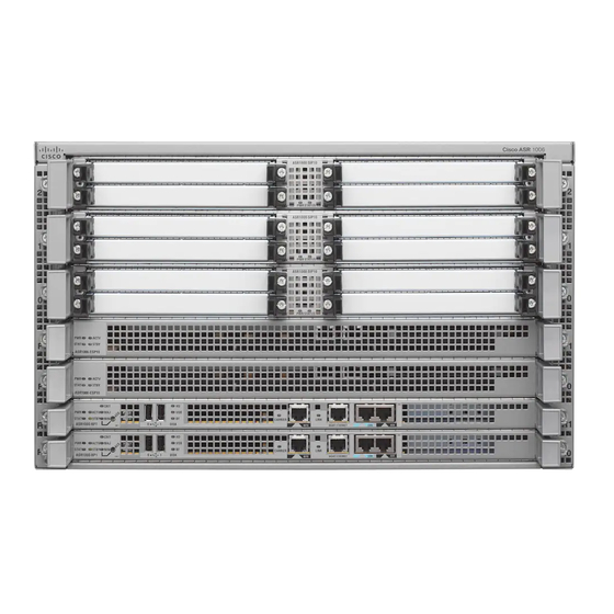
Ethernet ports are built into the chassis. • The Cisco ASR 1013 Router is a 24 half-height shared port adapters, 13-RU chassis that can hold 6 SIPs and provides superslots (more height and power) for the Cisco ASR1000-RP2s and Cisco ASR1000-ESPs. -
Page 37: Cisco Asr 1000 Series Router Features
IOS process. In this architecture, Cisco IOS, which previously was responsible for almost all of the internal software processes, now runs as one of many Cisco IOS XE processes while allowing other Cisco IOS XE processes to share responsibility for running the router. - Page 38 Cisco ASR 1000 Series Router Features • Online insertion and removal (OIR) capability • Route processor and embedded services processor redundancy in the Cisco ASR 1000 Series Routers (Cisco ASR 1013 Router and Cisco ASR 1006 Router) • Control processor for ASR 1000 Series SPA Interface Processor •...
-
Page 39: Cisco Asr 1000 Series Routers Compatibility Information
ASR1000-ESP200 can be installed only on Cisco ASR 1013 routers. Hardware Compatibility The following table lists the Cisco ASR 1000 Series Routers that support and are compatible with Cisco hardware products. Table 2: Cisco ASR 1000 Series Routers and Component Compatibility and Support Matrix... -
Page 40: Cisco Asr 1000 Series Router Hardware Installation Guide
ASR1000-SIP10 cannot be performed in slot 5. Cisco ASR1000-SIP10 can be upgraded only in any one of the slots from slots 0 to 4. • If Cisco ASR1000-RP1 is inserted into Cisco ASR 1013 Router, the card is disabled and an error message is generated The Cisco ASR 1013 Router supports only the following components: •... -
Page 41: Cisco Asr 1000 Series Router Configurations
Cisco ASR 1000 Series Router Configurations Existing Cisco ASR1000-RP2 and Cisco ASR1000-SIP10 cannot be used as is in the Cisco ASR 1013 Router. These two components must be upgraded to support Cisco IOS XE Release 3.1S on the Cisco ASR 1013 Router. -
Page 42: Functional Overview
SPA product feature cable management to allow installation and removal of adjacent cards without having to remove cables. The Cisco ASR 1002-F Router and Cisco ASR 1002-X Router use the same accessories as the Cisco ASR Note 1002 Router. -
Page 43: Chassis Slot And Logical Interface Numbering
Chassis Slot and Logical Interface Numbering The Cisco ASR 1000 Series Routers have a slot numbering system located on both sides of the card module location. The chassis slots are physically numbered from zero starting at the bottom of the chassis. This section describes the slot numbering for the Cisco ASR 1000 Series Routers: Cisco ASR 1000 Series SPA Interface Processor (SIP) subslots begin their numbering with “0”... -
Page 44: Online Insertion And Removal
The following is a functional description of OIR for background information only; for specific procedures for installing and replacing a shared port adapter in Cisco ASR 1000 Series Routers, refer to the online configuration note for each shared port adapter. -
Page 45: Environmental Monitoring And Reporting Functions
Cisco ASR 1000 Series Routers Hardware Overview Environmental Monitoring and Reporting Functions When you remove or insert a shared port adapter in a Cisco ASR 1000 Series Router, the Control Processor notifies the Cisco ASR1000-RP1, which in turn notifies the forwarding engine control processor (FECP), and then performs the following steps: •... -
Page 46: Fan Failures
It manages the ESI (Enhanced Serdes Interconnect) which are the datapath links on the midplane connecting the Cisco ASR 1000 Series RP1s, SIPs, and standby ESP modules to the active Cisco ASR 1000 Series Embedded Services Processor. It communicates with the chassis manager on the Cisco ASR 1000 Series Route Processor 1 to report the status and health, including detected hardware failures, ESI status, software process status, and the state of thermal sensors. -
Page 47: Cisco Asr 1000 Series Router Hardware Installation Guide
Parameters are measured and reporting functions are updated every 60 seconds. A brief description of each of these commands follows. Note The example outputs displayed in this section are from the Cisco ASR 1004 Router. Similar output is displayed for all Cisco ASR 1000 Series Routers. Router# show environment all... -
Page 48: Cisco Asr 1000 Series Router Hardware Installation Guide
License Notice file accompanying the IOS-XE software, or the applicable URL provided on the flyer accompanying the IOS-XE software. A summary of U.S. laws governing Cisco cryptographic products may be found at: http://www.cisco.com/wwl/export/crypto/tool/stqrg.html If you require further assistance please contact us by sending email to export@cisco.com. -
Page 49: Cisco Asr 1000 Series Router Hardware Installation Guide
NAME: module F0, DESCR: Cisco ASR1000 Embedded Services Processor, 10Gbps PID: ASR1000-ESP10 , VID: V00, SN: JAB111101A1 NAME: Power Supply Module 0, DESCR: Cisco ASR1004 AC Power Supply PID: ASR1004-PWR-AC , VID: V00, SN: ART1103K00C NAME: Fan Module 1, DESCR: Cisco ASR1004 Fan Module... -
Page 50: Cisco Asr 1000 Series Router Hardware Installation Guide
Version Identifier (VID) : V00 Manufacturing Test Data : 00 00 00 00 00 00 00 00 Field Diagnostics Data : 00 00 00 00 00 00 00 00 Asset ID : AAAAAAAAAAAAAAAAAAAAAAAAAAAAAAAA Cisco ASR 1000 Series Router Hardware Installation Guide... -
Page 51: Cisco Product Identification Standard
Cisco Product Identification Standard This section describes the Cisco products and services product identification standard. This feature provides you with the ability to effectively integrate and manage Cisco products in your network and business operations. Unique Device Identifier The Unique Device Identifier (UDI) is the Cisco product identification standard for hardware products. A product identification standard removes barriers to enterprise automation and can help you reduce operating expenses. -
Page 52: Serial Number Label Location
• Operating expense reduction— The Cisco UDI provides accurate and detailed network inventory information; identifying each Cisco product in a network element through a standard interface. Cisco operating systems can view and use this data, allowing you to automate your electronic inventory. -
Page 53: Cisco Asr 1000 Series Router Hardware Installation Guide
Cisco ASR 1000 Series Routers Hardware Overview Serial Number Label Location The following figure shows the serial number location for the Cisco ASR 1006 Router. Figure 1: Cisco ASR 1006 Router Serial Number Label Location Cisco ASR 1000 Series Router Hardware Installation Guide... -
Page 54: Cisco Asr 1000 Series Router Hardware Installation Guide
Cisco ASR 1000 Series Routers Hardware Overview Serial Number Label Location The following figure shows the serial number label location for the Cisco ASR 1004 Router. Figure 2: Cisco ASR 1004 Router Serial Number Label Location Cisco ASR 1000 Series Router Hardware Installation Guide... -
Page 55: Cisco Asr 1000 Series Router Hardware Installation Guide
Cisco ASR 1000 Series Routers Hardware Overview Serial Number Label Location The following figure shows the serial number label location for the Cisco ASR 1002 Router. Figure 3: Cisco ASR 1002 Router Serial Number Label Location Cisco ASR 1000 Series Router Hardware Installation Guide... -
Page 56: Cisco Asr 1000 Series Router Hardware Installation Guide
Cisco ASR 1000 Series Routers Hardware Overview Serial Number Label Location The following figure shows the serial number label location for the Cisco ASR 1002-F Router. Figure 4: Cisco ASR 1002-F Router Serial Number Label Location Cisco ASR 1000 Series Router Hardware Installation Guide... -
Page 57: Cisco Asr 1000 Series Router Hardware Installation Guide
Cisco ASR 1000 Series Routers Hardware Overview Serial Number Label Location The following figure shows the serial number label location for the Cisco ASR 1013 Router (Note that this is the bottom of the chassis). Figure 5: Cisco ASR 1013 Router Serial Number Label Location... -
Page 58: Cisco Asr 1000 Series Router Hardware Installation Guide
Cisco ASR 1000 Series Routers Hardware Overview Serial Number Label Location The following figure shows the serial number label location for the Cisco ASR 1001 Router. Figure 6: Cisco ASR 1001 Router Serial Number Label Location The following figure shows the serial number label location for the Cisco ASR 1002-X Router. -
Page 59: Cisco Asr 1000 Series Routers Component Overview
Cisco ASR 1000 Series Routers Component Software Support This section lists the new hardware supported on the Cisco ASR 1000 Series routers and the version of Cisco IOS software code required to support the component. xref table lists the components that are not supported by earlier releases of Cisco IOS XE. -
Page 60: Upgrading To New Software
Upgrading to New Software Note For a listing of the new SPAs, click the corresponding link in the table. Table 5: Cisco ASR 1000 Series Router Component Software Support Cisco IOS XE Software Support Cisco Hardware Components Cisco IOS XE Release 2.1.0 •... -
Page 61: Supported Asr 1000 Hardware Components
Cisco IOS XE Release 2.6.0 1-Port Channelized OC-12/STM-4 SPA (SPA-1XCHOC12/DS0) Cisco IOS XE 3.1S (formerly Release 2.7.0) • Chapter 11, “Cisco ASR 1013 Router Overview and Installation” • Chapter 3, “Cisco ASR 1000 Series Routers Embedded Services Processors” • Chapter 4, “Cisco ASR 1000 Series Router SPA Interface Processors (SIPs)”... -
Page 62: Supported Cisco Asr 1000 Platforms
Cisco ASR 1000 Series Routers Component Overview Supported Cisco ASR 1000 Platforms Supported Cisco ASR 1000 Platforms The following table lists the Cisco ASR 1000 Series Routers and the hardware components supported in each router. Table 6: Supported Cisco ASR 1000 Platforms and Components... -
Page 63: Cisco Asr 1000 Series Hardware Configuration Combinations
This section provides Cisco ASR 1000 Series hardware configuration combinations and whether they are supported from Cisco IOS XE Release 3.1S onward. The tables list the router and the route processor, SIPs, and power modules supported on that router. The tables include the following categories •... -
Page 64: Hardware Requiring A Cpld Upgrade
• Cisco ASR1000-ESP40 is inserted into Cisco ASR 1002 Router • Cisco ASR1000-ESP100 is inserted into Cisco ASR 1002 Router • Cisco ASR1000-ESP5 or Cisco ASR1000-ESP100 is inserted into Cisco ASR 1004 Router or ASR 1006 Router Cisco ASR 1000 Series Router Hardware Installation Guide... -
Page 65: Incompatible Asr1000-Rp Error Message
Remove the embedded services processor from the chassis. Incompatible ASR1000-RP Error Message This section describes what happens when a Cisco ASR1000-RP1 is inserted into the Cisco ASR 1013 router and provides the error message and explanation as to why this occurred: Error message The ASR1000-RP1 is disabled and the following error message displays at the console. -
Page 66: Unsupported Asr1000-Esp Error Message
This section describes what happens when a Cisco ASR1000-ESP40 is present when the router is booting or inserted at a later time into the Cisco ASR 1000 Router and provides the error message and explanation as to why this occurred. -
Page 67: Unsupported Asr1000-Sip Error Message
This section describes what happens when a Cisco ASR1000-SIP40 is present when the router is booting or inserted at a later time into the Cisco ASR 1000 Router and provides the error message and explanation as to why this occurred. -
Page 68: Unsupported Active Asr1000-Rp2 Requires Upgrade
Previously released Cisco ASR1000-RP2 and Cisco ASR1000-SIP10 modules are not compatible when inserted in the Cisco ASR 1013 Router. If an incompatible component is inserted into the Cisco ASR 1013 Router, Cisco software detects the out-of-revision hardware. In order to reuse the Cisco ASR1000-RP2 and Cisco ASR1000-SIP10 in the Cisco ASR 1013 Router, you must perform a CPLD field programmable hardware upgrade on these modules. -
Page 69: When To Perform A Cpld Upgrade
This section describes what happens when a standby Cisco ASR1000-RP2 or Cisco ASR1000-SIP10 with an older version of CPLD is inserted into the Cisco ASR 1013 Router. The error message that is displayed on the console and the message explanation and recommended action are described. -
Page 70: Image To Upgrade Field-Programmable Hardware Devices
An image is provided for the field programmable device to customers in cases where a field upgrade is required. If the Cisco ASR 1000 Series Router contains an earlier released version of the hardware programmable firmware on the Cisco ASR1000-RP, Cisco ASR1000-SIP, or Cisco ASR 1000-ESP, then that hardware programmable firmware may need to be upgraded. -
Page 71: Cisco Asr 1000 Series Route Processor Differences
• Include control signals for monitoring the health of power entry modules, shutting down the power and driving alarm relays located on the power entry modules. • The Cisco ASR 1000 Series route processor modules can be configured with either a 40 GB or a 32 GB disk. -
Page 72: Cisco Asr 1000 Series Router Hardware Installation Guide
Cisco ASR 1002 Router. The Cisco ASR 1000 Series route processor modules consist of a front panel label for indicator and control functions and a separate label for the I/O connectors. The Cisco ASR1000-RP1 and Cisco ASR1000-RP2 model number labeling is located next to the left card module handle. -
Page 73: Cisco Asr 1000 Series Router Hardware Installation Guide
Cisco ASR 1000 Series Routers Component Overview Cisco ASR 1000 Series Route Processor Differences The following figure shows the Cisco ASR 1000 Series Route Processor faceplate. Figure 8: Cisco ASR1000-RP Route Processor Faceplate LEDs and Connectors Internal hard drive LED... -
Page 74: Cisco Asr 1000 Series Router Hardware Installation Guide
Cisco ASR 1000 Series Routers Component Overview Cisco ASR 1000 Series Route Processor Differences The following table lists the Cisco ASR 1000 Series Route Processor LEDs and behavior. Table 10: Cisco ASR 1000 Series Route Processor LEDs LED Label Color —State... -
Page 75: Cisco Asr 1000 Series Router Hardware Installation Guide
LINK 10/100/1000 RJ-45 Solid Green Link with no activity. Interface LED Flashing Green Link with Activity. No link. The following table lists the Cisco ASR 1000 Series Route Processors connectors and description. Cisco ASR 1000 Series Router Hardware Installation Guide... -
Page 76: Cisco Asr 1000 Series Router Hardware Installation Guide
Note configured, the connection is not established and a call cannot be setup. This functionality is not supported on any of the Cisco ASR 1000 Series Aggregation Services Routers or on any of the Cisco IOS XE versions. The Cisco ASR 1000 Series Route Processor meets the following requirements: •... -
Page 77: Cisco Integrated Asr1000-Rp1 For Cisco Asr 1002 Router
• 2 MB upgradeable BootROM, 1 GB Embedded USB memory (eUSB) • Comes with 2 GB of DRAM as default and can be upgradeable to 4 GB DRAM (except for the Cisco ASR 1002 embedded route processor). -
Page 78: Cisco Asr 1000 Series Router Hardware Installation Guide
• The LED order is from top to bottom on the route processor is MIN, MAJ, CRIT. • The Cisco ASR1000-RP2 is not supported on the Cisco ASR 1002 router or Cisco ASR 1002-F router The following table lists the Cisco embedded ASR1000-RP1 LEDs and behaviors. -
Page 79: Cisco Asr 1000 Series Router Hardware Installation Guide
Cisco ASR 1000 Series Routers Component Overview Cisco Integrated ASR1000-RP1 for Cisco ASR 1002 Router LED Label Color —State Behavior Description System failure or powering up. Minor Amber Minor alarm indicator. Major Major alarm indicator. CRIT Critical Critical alarm indicator. -
Page 80: Cisco Asr 1000 Series Router Hardware Installation Guide
Cisco ASR 1002 built-in GE ports support only the SFP-GE-T but not the SFP-GLC-T. The following table lists the Cisco embedded ASR1000-RP1in the Cisco ASR 1002 Router connectors and description. Table 13: Cisco Embedded ASR1000-RP1 Connectors Label Type... -
Page 81: How Cisco Asr1000-Rp Alarm Monitoring Works
The external element is a DC light bulb for a visual alarm and a bell for an audible alarm. If an alarm illuminates the CRIT, MIN, or MAJ LED on the Cisco ASR 1000 Series Route Processor (RP) faceplate, and a visual or audible alarm is wired, the alarm also activates an alarm relay in the power supply DB-25 connector (on the Cisco ASR 1006 Router and Cisco ASR 1004 Router). -
Page 82: Cisco Asr 1000 Series Router Power Supplies
You are required to always have two power supplies installed in the chassis to insure sufficient cooling for the box. The system fans are inside the power supply unit and must spin for cooling. No Cisco ASR 1000 Series Router will operate for more than two to three minutes without two power supplies installed. Since all the system fans can be powered by one power supply, it is not required for the second power supply unit to be powered on, but it must be installed. -
Page 83: Power Supply Requirements For All Cisco Asr 1000 Series Routers
• AC and DC power supply ratings DC Power System Input Requirements for Cisco ASR 1000 Series Routers The DC power supply for the Cisco ASR 1006, Cisco ASR 1004, Cisco ASR 100, Cisco ASR 1013, and Cisco ASR 1001 routers operate at individual specifications. -
Page 84: Ac And Dc Power Supply Types
30 A circuit breaker. Note All Cisco ASR 1000 Series Router AC power supplies must be connected to a branch circuit that does not exceed 20 A. AC and DC Power Supply Types The AC and DC power supplies for the Cisco ASR 1000 Series Routers support different types of power supply switches. -
Page 85: Ac And Dc System Power Ratings
Power Supplies for the Cisco ASR 1013 Router, on page The Cisco ASR 1006 Router can support up to 1200 W output (AC and –48 VDC input). The 1200 W power supply module consists of either an AC or –48 VDC input and 1200 watt output closed frame power supply with two DC voltage outputs: 12 V and 3.3 V. -
Page 86: Ac Power Supply Leds And Connector For Cisco Asr 1006
AC power supplies for the Cisco Aggregation Services Routers: 120 VAC, 20A U.S. maximum. DC power supplies for the Cisco ASR 1006 Router: 50A U.S. maximum; Cisco ASR 1004 Router: 40A U.S. maximum: Cisco ASR 1002 Router: 30A U.S. maximum. Statement... -
Page 87: Cisco Asr 1000 Series Router Hardware Installation Guide
Cisco ASR 1000 Series Routers Component Overview AC Power Supply LEDs and Connector for Cisco ASR 1006 AC power supply fan AC power supply handle DB-25 alarm connector AC power inlet Tie-wrap tab AC power supply standby switch AC power supply captive... -
Page 88: Cisco Asr 1000 Series Router Hardware Installation Guide
Figure 11: Cisco ASR 1006 Router AC Power Supply LEDs and DB-25 Alarm Connector AC power supply LEDs DB-25 alarm connector AC power supply fan AC power supply fan The following table describes the AC power supply LEDs on the Cisco ASR 1006 Router. Cisco ASR 1000 Series Router Hardware Installation Guide... -
Page 89: Cisco Asr 1000 Series Router Hardware Installation Guide
Cisco ASR 1000 Series Routers Component Overview AC Power Supply LEDs and Connector for Cisco ASR 1006 Table 17: Cisco ASR 1006 Router AC Power Supply LEDs LED Label Color Description INPUT OK Power supply activity Green LED illuminates green to... -
Page 90: -48 Vdc Power Supply Leds And Connectors For Cisco Asr 1006
See xref figure. Note The studs on the terminal block are similar to the safety ground device on the side of the Cisco ASR 1006 Router. For information on the safety ground lug on the side of the chassis. -
Page 91: Cisco Asr 1000 Series Router Hardware Installation Guide
(O) switch Grounding symbol Power supply LEDs The following table describes the power supply LEDs and connectors on the rear of the chassis. Table 18: Cisco ASR 1006 Router – 48 VDC Power Supply LEDs LED Label Color Description INPUT OK... -
Page 92: Ac/Dc Power System Output For Cisco Asr 1006
The power supply output tolerance is defined in the following table under all combinations of line variation. Total system consumption per power supply should not exceed 1200 W. Table 19: Cisco ASR 1006 Router Power System Output Voltage and Current Output Voltage +12 VDC +3.3 V... -
Page 93: Power Supplies For The Cisco Asr 1004 Router
Power Supplies for the Cisco ASR 1004 Router The Cisco ASR 1004 Router can support up to 735 W output (AC and –48 VDC input). The 735 W power supply module consists of either an AC or –48 VDC input with two DC voltage outputs: 12 V and 3.3 V. -
Page 94: Cisco Asr 1004 Ac Power Supply Leds And Connector
Cisco ASR 1004 AC Power Supply LEDs and Connector Cisco ASR 1004 AC Power Supply LEDs and Connector The following figure shows the AC power supplies at the rear of the Cisco ASR 1004 Router.The Cisco ASR 1004 Router supports up to two power supplies. -
Page 95: Cisco Asr 1000 Series Router Hardware Installation Guide
Cisco ASR 1004 AC Power Supply LEDs and Connector The following figure shows the AC power supply LEDs and DB -25 alarm connector. Figure 14: Cisco ASR 1004 Router AC Power Supply LEDs and DB -25 Alarm Connector AC power supply LEDs... -
Page 96: Cisco Asr Router 1004 -48 Vdc Power Supply
The –48 VDC power supply operates within specification from –48 VDC to –60 VDC continuously. The Cisco ASR 1004 Router has two of the same type power supplies in power supply slot 0 and power supply slot 1. The power supply slot numbers are on the left side of the chassis and the power supplies are located on the floor of the chassis. -
Page 97: Cisco Asr 1004 Router -48 Vdc Power Supply Leds And Connector
Cisco ASR 1004 Router –48 VDC Power Supply LEDs and Connector The following figure shows the –48 VDC power supplies at the rear of the Cisco ASR 1004 Router. The Cisco ASR 1004 Router supports up to two power supplies. -
Page 98: Cisco Asr 1000 Series Router Hardware Installation Guide
Cisco ASR 1000 Series Routers Component Overview Cisco ASR 1004 Router –48 VDC Power Supply LEDs and Connector Table 21: Cisco ASR 1004 Router – 48 VDC Power Supply LEDs LED Label Color Description INPUT OK A bi-color LED indicates... -
Page 99: Dc Power System Input For Cisco Asr 1004
–48 VDC input turn on threshold of –43.5 V has been reached. The following table shows the common input ranges for reference only. Table 22: Cisco ASR 1004 Router – 48 VDC Power System Input Voltage Range (VDC) -
Page 100: Power Supplies For The Cisco Asr 1002 Router
This section provides information about the AC power supplies on the rear of the Cisco ASR 1002 Router. The Cisco ASR 1002 Router system level cooling is provided by two 12 VDC type fans in each of the two power supply modules. The fans in each module are intended to provide system cooling back-up in the event of a single fan failure. -
Page 101: Cisco Asr 1002 Ac Power Supply Leds And Connector
(chassis rear) to secure these modules into the chassis. Cisco ASR 1002 AC Power Supply LEDs and Connector The following figure shows the AC power supplies at the rear of the Cisco ASR 1002 Router. The Cisco ASR 1002 Router supports up to two power supplies. -
Page 102: Ac Power System Output Voltage Alarm Range For Cisco Asr 1002 Router
Cisco ASR 1002 Router –48 VDC Power Supply This section provides information about the –48 VDC power supplies on the rear of the Cisco ASR 1002 Router. The recommended branch circuit breaker for the Cisco ASR 1002 Router –48 VDC power supply is... -
Page 103: Cisco Asr 1002 Router -48 Vdc Power Supply Leds And Connector
VDC power supply module must not exceed 30 A. The Cisco ASR 1002 Router has two of the same type power supplies in power supply slot 0 and power supply slot 1. The power supply slot numbers are on the left side of the chassis and the power supplies are located on the floor of the chassis. -
Page 104: -48 Vdc Power System Input For Cisco Asr 1002 Router
Cisco ASR 1000 Series Routers Component Overview Cisco ASR 1002 Router –48 VDC Power Supply Table 26: Cisco ASR 1002 Router – 48 VDC Power Supply LEDs LED Label Color Description INPUT OK A bi-color LED indicates Green LED illuminates green to signal presence of input voltage that the –48 VDC power supply... -
Page 105: -48 Vdc Power System Output For Cisco Asr 1002 Router
40 A UL listed circuit breaker. The Cisco ASR 1002 Router has two of the same type power supplies in power supply slot 0 and power supply slot 1. The power supply slot identifiers are zero (0) on the left side of the chassis rear and one (1) on the right side of the chassis rear. -
Page 106: Cisco Asr 1002 Router +24 Vdc Power Supply Leds And Connector
Cisco ASR 1002 Router +24 VDC Power Supply LEDs and Connector The following figure shows the +24 VDC power supplies at the rear of the Cisco ASR 1002 Router. The Cisco ASR 1002 Router supports two +24 VDC power supplies. -
Page 107: Cisco Asr 1000 Series Router Hardware Installation Guide
+27V; but generically, these power systems can be labeled +24 V and referred to as +24 VDC (see the following figure for more information). Figure 19: Cisco ASR 1002 Router Rear View With +24 VDC Power Supply Terminal Block Positive (+) lead... -
Page 108: +24 Vdc Power System Input For Cisco Asr 1002 Router
Two power supplies are used for redundant operation. System total power consumption shall never exceed Note rating of one power supply to maintain redundancy. Table 30: Cisco ASR 1002 Router +24 VDC Power System Output Voltage and Current Output Voltage +12 VDC +3.3 V... -
Page 109: Cisco Asr 1000 Series Router Hardware Installation Guide
Note +24 VDC Power Supply Important Notices The following items list important notes regarding the +24 VDC power supply in the Cisco ASR 1002 Router: • Output Voltage Alarm Threshold—The Output Voltage Alarm is declared when the output voltage is below the low end of the minimum or above the high end of the maximum limits (as shown in the following table). -
Page 110: Power Supplies For The Cisco Asr 1013 Router
1013 Router. The Cisco ASR 1013 Router can support up to 1600 W output and operates between 180 VAC and 260 VAC. The 1600 W power supply module consists of either an AC or –48 VDC input and 1600 watt output closed frame power supply with two DC voltage outputs: +12 V and +3.3 V can be used as a single supply, dual,... -
Page 111: Ac Power Supply Leds And Connector For Cisco Asr 1013
This section provides information about the AC power supplies on the rear of the Cisco ASR 1013 Router. The power supply module contains three fans. A total of six fans are used to cool the ASR 1013 system and power supply. The airflow direction is front to back. -
Page 112: Cisco Asr 1000 Series Router Hardware Installation Guide
Figure 20: Cisco ASR 1013 Router AC Power Supply LEDs and DB-25 Alarm Connector AC power supply LEDs DB-25 alarm connector AC power supply fan AC power supply fan The following table describes the AC power supply LEDs on the Cisco ASR 1013 Router. Cisco ASR 1000 Series Router Hardware Installation Guide... -
Page 113: Cisco Asr 1000 Series Router Hardware Installation Guide
Cisco ASR 1000 Series Routers Component Overview AC Power Supply LEDs and Connector for Cisco ASR 1013 Table 32: Cisco ASR 1013 Router AC Power Supply LEDs LED Label Color Description INPUT OK Power supply activity Green LED illuminates green to... -
Page 114: -48 Vdc Power Supply Leds And Connectors For Cisco Asr 1013
The –48 VDC power supply operates within specification from –40.5 VDC to –72 VDC continuously. The Cisco ASR 1013 Router has two of the same type power supplies in power supply slot 0 and power supply slot 1. The power supply slot numbers are on the left side of the chassis and the power supplies are located on the floor of the chassis. -
Page 115: Cisco Asr 1000 Series Router Hardware Installation Guide
DC power supply ground Power supply LEDs studs The following table describes the power supply LEDs and connectors on the rear of the chassis. Table 33: Cisco ASR 1013 Router – 48 VDC Power Supply LEDs LED Label Color Description... -
Page 116: Ac/Dc Power System Output For Cisco Asr 1013
The output tolerance values shown in this table apply to the ASR1013/06-PWR-DC and Note ASR1013/06-PWR-AC power supplies. The Cisco ASR 1013 Router and the Cisco ASR 1006 Router support these power supplies. Table 34: Cisco ASR 1013 Router Power System Output Voltage and Output Current... -
Page 117: Power Supplies For The Cisco Asr 1001 Router
12 V output and is used in a dual hot pluggable configuration. The DC power supply consumes a maximum of 500 W of input power. The Cisco ASR 1001 Router can support two AC or two DC power supplies. Do not install the AC and Note DC power supply units in the same chassis. -
Page 118: Cisco Asr 1001 Router Ac Power Supply
Cisco ASR 1001 Router AC Power Supply The Cisco ASR 1001 Router has two AC power supplies in the rear of the chassis. The input receptacle is an IEC60320 C14 type of filtered AC inlet. The current rating on the connector is 10 A. The following figure shows the ASR 1001 Router AC power supplies. -
Page 119: Ac/Dc Power System Input Range And Voltage For Cisco Asr 1001
The power supply has a handle to be used for insertion and extraction. The module must be supported with one hand because of its length. The following figure shows the Cisco ASR 1001 Router DC power supplies. Figure 24: Cisco ASR 1001 Router With DC Power Supplies... -
Page 120: Cisco Asr 1000 Series Router Hardware Installation Guide
Cisco ASR 1000 Series Routers Component Overview Cisco ASR 1001 Router DC Power Supply Cisco ASR 1000 Series Router Hardware Installation Guide... -
Page 121: Chapter 3 Cisco Asr 1000 Series Routers Embedded Services Processors
Additionally, the Cisco ASR 1002 Fixed Router includes a nonmodular, fixed embedded services processor with a throughput of 2.5 Gbps and the Cisco ASR 1001 Router has a nonmodular, fixed embedded services processor with a throughput of 2.5 Gbps, which is upgradable with a software activated performance upgrade license to 5 Gbps. -
Page 122: Cisco Asr 1000-Esp5
The embedded services processor can be upgraded only on redundant embedded services processor systems Note (Cisco ASR 1006 Router and Cisco ASR 1013 Router). The Cisco ASR 1002 router supports only one Cisco ASR1000-ESP5 or ASR1000-ESP10. The Cisco ASR 1006 Router and Cisco ASR 1004 Router do not support the Cisco ASR1000-ESP5. -
Page 123: Cisco Asr 1000-Esp10
The Cisco ASR1000 Embedded Services Processor 10G Non Crypto Capable feature support is the same as the Cisco ASR100-ESP10 except that SSH, SSL and IPSec VPN services are not supported. For detailed information... -
Page 124: Cisco Asr 1000-Esp100
Cisco ASR1000-ESP100 provides the following features: • 24 configurable ESI links for SPA Carrier Card and native Line Card support: ◦ ESI links support with a bandwidth of up to 46 Gbps for the Cisco ASR 1013 Router on Sip slots 0,1,4, and 5. -
Page 125: Cisco Asr 1000-Esp200
Cisco ASR1000-ESP200 provides the following features: • 24 configurable ESI links for SPA Carrier Card and native Line Card support: ◦ ESI links support with a bandwidth of up to 46 Gbps for the Cisco ASR 1013 Router on Sip slots 0,1,4, and 5. - Page 126 Cisco ASR 1000 Series Routers Embedded Services Processors Cisco ASR 1000-ESP200 and Third Generation Cisco QFP The following figure displays the SIP and SPA bays of the Cisco ASR 1013 Router and their mappings to the QFP-3rd-Gen ASICs. Figure 25: Cisco ASR 1000-ESP200 and their QFP-3rd-Gen ASIC Mappings...
-
Page 127: Implications Of Sip And Spa Slot Mapping
QFP-3rd-Gen 2 QFP-3rd-Gen 0 The following figure displays an example of a packet flow in the Cisco ASR 1000 ESP 200. Figure 26: Packet flow in the Cisco ASR 1000 ESP 200 Implications of SIP and SPA Slot Mapping Interfaces and sessions that have an egress QoS have their schedules and queues present in the QFP-3rd-Gen ASIC that services the particular slot. -
Page 128: Features Of The Cisco Asr 1000 Series Embedded Services Processors
QFP-3rd-Gen ASIC. This will enable additional schedules and queues. Features of the Cisco ASR 1000 Series Embedded Services Processors The following table summarizes the features of the embedded services processors. Table 36: Differences in Cisco ASR 1000 Series Embedded Services Processors Embedded Services Memory Performance... - Page 129 Cisco ASR 1000 Series Routers Embedded Services Processors Features of the Cisco ASR 1000 Series Embedded Services Processors Embedded Services Memory Performance Bandwidth Security Traffic Processor Performance Cisco Same as Cisco ASR Same as the Cisco Limited to 2.5 Gbps...
- Page 130 Cisco ASR 1000 Series Routers Embedded Services Processors Features of the Cisco ASR 1000 Series Embedded Services Processors Embedded Services Memory Performance Bandwidth Security Traffic Processor Performance Cisco 100 Gbps 20 Gbps • Dual Quantum ASR1000-ESP100 Flow packet processor complex: ◦...
- Page 131 DIMMs 1 While both the Cisco ASR1000-ESP40 and ASR1000-ESP20 exceed the 16 Mpps forwarding rate, the ESP40 packets per second rate is slightly less than ESP20 when sending continuous stream of small, 64-byte packets. However, at 92 bytes and larger, the ASR1000-ESP40 outperforms ESP20. The difference at small packet sizes is a side-effect of optimizations made to achieve 40 Gbps for medium to large packets.
- Page 132 Cisco ASR 1000 Series Routers Embedded Services Processors Features of the Cisco ASR 1000 Series Embedded Services Processors The Cisco ASR 1000 Series embedded services processors have the same faceplate and status information Note except for the name label, such as Cisco ASR1000-ESP40, Cisco ASR1000-ESP20, Cisco ASR1000-ESP10, Cisco ASR1000-ESP10-N, and Cisco ASR1000-ESP5.
- Page 133 Cisco ASR 1000 Series Routers Embedded Services Processors Features of the Cisco ASR 1000 Series Embedded Services Processors LED Label Color Behavior Description System failure or powering up. ACTV Active Green The ACTV LED indicates (in a redundant system) the embedded services...
- Page 134 Cisco ASR 1000 Series Routers Embedded Services Processors Features of the Cisco ASR 1000 Series Embedded Services Processors Cisco ASR 1000 Series Router Hardware Installation Guide...
-
Page 135: Chapter 4 Cisco Asr 1000 Series Router Spa Interface Processors (Sips)
Cisco ASR 1000 Series SPA Interface Processor This section describes the Cisco SPA interface processors for the Cisco ASR 1006, Cisco ASR 1004, Cisco ASR 1002, and Cisco ASR 1013 routers. The Cisco ASR 1000 Series Routers support the following Cisco ASR 1000-SIPs: •... - Page 136 2 full height Cisco SPAs. The is a list of characteristics of the Cisco ASR 1000 Series SPA Interface Processors for the Cisco ASR 1006, Cisco ASR 1004, and Cisco ASR 1013 routers: •...
- Page 137 Cisco ASR 1000 Series Router SPA Interface Processors (SIPs) Cisco ASR 1000 Series SPA Interface Processor SPA subslot 2 SPA subslot 3 Figure 28: Cisco ASR1000-SIP10 SPA Interface Processor, on page 103 shows the LEDs on the Cisco ASR1000-SIP10. Figure 28: Cisco ASR1000-SIP10 SPA Interface Processor...
-
Page 138: Spa Interface Processor Slot Numbering
• Two half-height and 1 full-height combination that does not exceed 64 ports The slot numbering for the SPAs in the Cisco ASR 1004 Router is the same as in the Cisco ASR 1006 Router. Cisco ASR 1000 Series Router Hardware Installation Guide... -
Page 139: Cisco Asr 1002 Router
Cisco ASR 1006 Router and Cisco ASR 1004 Router. Figure 29: Cisco ASR 1004 Router and Cisco ASR 1006 Router SPA Interface Subslot Numbering The slot numbering for the SPAs on the Cisco ASR 1004 Router is the same as the numbering on the Note Cisco ASR 1006 Router. -
Page 140: Cisco Asr 1002-F Router
• Built-in 4xGE SPA in bay 0, one half height SPA in bay 2, and one full height SPA in bay 1. The Cisco ASR 1000 Series SPA interface processor houses SPA bay 2 and SPA bay 3. SPA bay 0 and SPA bay 1 are physically located on Cisco integrated ASR1000-RP1. -
Page 141: Cisco Asr 1013 Router
• Two full-height (¼ Rate or full rate or combination) SPAs with up to 48 ports per SPA • Two half-height and 1 full-height combination that does not exceed 96 ports The Cisco ASR 1013 Router uses the same SPA subslot numbering as the Cisco ASR 1006 and Cisco ASR 1004 routers. - Page 142 Cisco ASR 1000 Series Router SPA Interface Processors (SIPs) Cisco ASR 1013 Router Figure 31: Cisco ASR 1013 Router Slot Numbering , on page 108 shows the slot numbering for the shared port adapters on the Cisco ASR 1013 Router.
-
Page 143: Cisco Asr 1001 Router
For detailed information about specifying SIP subslot location for a SPA and specifying slot location for a SIP, see Cisco Aggregation Services Router 1000 Series SIP and SPA Software Configuration Guide Cisco ASR 1001 Router In the Cisco ASR 1001 Router, the Cisco ASR1000-SIP10 supports: •... -
Page 144: Cisco Asr 1002-X Router
• Three removable half-height SPAs in Bays 1, 2, and 3 • A built-in 6xGE SPA The SPAs on the Cisco ASR1002-X support online insertion and removal. However, the SIP on the Cisco Note ASR 1002-X Router is built into the chassis and is not a field-replaceable unit. -
Page 145: Preparing Your Site For Installation
C H A P T E R Preparing Your Site for Installation This chapter contains important safety information you should know before working with the Cisco ASR 1000 Series Aggregation Services Routers and guides you through the process of preparing your site for router installation. -
Page 146: Safety Guidelines
• Router should always be transported or stored in its shipping package in the upright position. • Keep the router in the shipping container until you have determined the installation site. Inspect all items for shipping damage. If an item appears damaged, contact a Cisco customer service Note representative immediately. -
Page 147: Safety Recommendations
. • Cisco safety policy is that all of its routers must conform to the requirements of IEC 60950, with appropriate national deviations, as a minimum. In addition, Cisco routers must also meet the requirements of any other normative documents (for example, standards, technical specifications, laws or regulations). -
Page 148: Cautions And Regulatory Compliance Statements For Nebs
Regulatory, Compliance, and Safety Information for the Cisco Aggregation Services Router 1000 Series . Cautions and Regulatory Compliance Statements for NEBS The following table lists cautions, regulatory compliance statements, and requirements for the Network Equipment-Building System (NEBS) certification from the Telcordia Electromagnetic Compatibility and Electrical Safety –... -
Page 149: Standard Warning Statements
To comply with the Class A emissions requirements shielded twisted pair T1/E1 cables must be used for Warning SPA-8-Port Channelized T1/E1 SPA (SPA-8XCHT1/E1) on the Cisco ASR 1006, ASR 1004, and ASR 1002. EN55022/CISPR22 Statement Cisco ASR 1000 Series Router Hardware Installation Guide... - Page 150 Electrical Appliance and Material Safety Law prohibits the use of certified cables (that have the ‘UL’ shown on the code) for any other electrical devices than products designated by Cisco. The use of cables that are certified by Electrical Appliance and Material Safety Law (that have ‘PSE’ shown on the code) is not limited to Cisco-designated products.
- Page 151 Dispose of used batteries according to the manufacturer’s instructions. Statement 1015 Do not touch or bridge the metal contacts on the battery. Unintentional discharge of the batteries can cause Warning serious burns. Statement 341 Cisco ASR 1000 Series Router Hardware Installation Guide...
-
Page 152: Site Planning
Do not operate the system unless all cards, faceplates, front covers, and rear covers are in place. Statement 1029 Site Planning This section contains site planning information, and will help you plan for the installation of the Cisco ASR 1000 Series Routers. General Precautions Observe the following general precautions when using and working with your Cisco ASR 1000 Series Routers. -
Page 153: Site Selection Guidelines
The Cisco ASR 1000 Series Routers are designed to meet the industry EMC, safety, and environmental standards described in the Regulatory Compliance and Safety Information for the Cisco ASR 1000 Series Aggregation Services Routers document. -
Page 154: Physical Characteristics
Site Selection Guidelines Physical Characteristics Be familiar with the physical characteristics of the Cisco ASR 1000 Series Router to assist you in placing the system at the proper location. For information regarding rack widths supported for ASR 1000 Routers, see the following sections: 19 in.—... - Page 155 (94.61 kg) with 2 Unless otherwise noted, the physical characteristics for the Cisco ASR 1002-F Router and Cisco ASR 1002-X Router remain the same as those for the Cisco ASR 1002 Router. The following list describes additional Cisco ASR 1000 Series chassis characteristics: •...
-
Page 156: Floor Loading Considerations
◦ Ships with forward rack-mount brackets installed and an extra set in the accessory kit Floor Loading Considerations Ensure that the floor under the rack supporting the Cisco 1000 Series Routers is capable of supporting the combined weight of the rack and all other installed equipment. -
Page 157: Site Power Guidelines
The Cisco ASR 1000 Series Routers can be powered by a DC or AC source. Ensure that the equipment grounding is present and observe power strip ratings. Make sure that the total ampere rating of all products plugged into the power strip does not exceed 80% of the rating. - Page 158 All Cisco ASR 1000 Series Router AC power supplies require a 20 A circuit breaker. Note The AC and DC power supplies for the Cisco ASR 1000 Series Routers support different types of power supply switches. The following table lists AC and DC power supply system rating requirements for all Cisco ASR 1000 Series Routers.
-
Page 159: Site Cabling Guidelines
This section contains guidelines for wiring and cabling at your site. When preparing your site for network connections to the Cisco 1000 Series Router, consider the type of cable required for each component, and the cable limitations. Consider the distance limitations for signaling, EMI, and connector compatibility. Possible cable types are fiber, thick or thin coaxial, foil twisted-pair, or unshielded twisted-pair cabling. -
Page 160: Asynchronous Terminal Connections
Strong EMI can destroy the signal drivers and receivers in the Cisco ASR 1000 Series Router and even create an electrical hazard by causing power surges through power lines into installed equipment. These problems are rare, but could be catastrophic. -
Page 161: Radio Frequency Interference
If signal wires exceed recommended cabling distances, or if signal wires pass between buildings, you should consider the effect that a lightning strike in your vicinity might have on the Cisco ASR 1000 Series Router. The electromagnetic pulse (EMP) generated by lightning or other high-energy phenomena can couple enough energy into unshielded conductors to damage or destroy electronic equipment. -
Page 162: General Rack Selection Guidelines
Guidelines for 23 in. (Telco) Racks If needed, you can also install the Cisco ASR 1000 Series Routers in 23 in. (Telco) racks. For information on adapters needed for 23 in. racks, please contact the Newton Instrument Company: •... -
Page 163: Equipment Rack Guidelines
Locating for Safety If the Cisco ASR 1000 Series Router is the heaviest or the only piece of equipment in the rack, consider installing it at or near the bottom to ensure that the rack center of gravity is as low as possible. -
Page 164: Locating For Proper Airflow
Avoid locating the Cisco 1000 Series Router in a location in which the chassis air intake vents could draw in the exhaust air from adjacent equipment. Consider how the air flows through the Cisco 1000 Series Router. -
Page 165: Electrical Safety
These screws prevent accidental removal of the module, provide proper grounding for the system, and help ensure that the bus connectors are properly seated in the backplane. The ESD strap socket can be in a different location on each Cisco ASR 1000 Series Router. Note Electrical Safety All system components are hot-swappable. -
Page 166: Receiving The Cisco Asr 1000 Series Router
1006 Receiving the Cisco ASR 1000 Series Router Each Cisco ASR 1000 Series chassis is shipped in a container that is strapped to a pallet as illustrated in the following figure. Figure 33: Cisco ASR 1000 Series Router Packaged for Shipping... -
Page 167: Chassis-Lifting Guidelines
Each person should stand on either side of the chassis and place one hand under the air intake at the bottom front of the chassis. Step 2 With the other hand, grasp the top rear of the chassis under the air exhaust and carefully lift the chassis. Cisco ASR 1000 Series Router Hardware Installation Guide... -
Page 168: Tools And Equipment
4. After you have unpacked the system verify that you have received all of the required components. Using the packing list as a guide, take the following steps to check the contents of the Cisco ASR 1000 Series Router shipping container: 5. -
Page 169: Checking The Shipping Container Contents
After you have unpacked the system verify that you have received all of the required components. Using the packing list as a guide, take the following steps to check the contents of the Cisco ASR 1000 Series Router shipping container: Step 5 Check the contents of the boxes containing accessory items. -
Page 170: Cisco Asr 1000 Series Router Installation Checklist
To assist you with your installation and to provide a historical record of what was done by whom, photocopy the Cisco ASR 1000 Series Router Installation Checklist shown in the following table. Use this to record when each procedure or verification is completed. When the checklist is completed, place it in your site log along with the other records for your new router. -
Page 171: Cisco Asr 1000 Series Router Installation Checklist
Preparing Your Site for Installation Cisco ASR 1000 Series Router Installation Checklist Table 46: Cisco ASR 1000 Series Router Installation Checklist Task Verified By Date Date chassis received Chassis and all accessories unpacked Types and numbers of interfaces verified Safety recommendations and... -
Page 172: Cisco Asr 1000 Series Router Installation Checklist
Preparing Your Site for Installation Cisco ASR 1000 Series Router Installation Checklist Task Verified By Date Shared port adapters are operational Correct hardware configuration displayed after system banner appears Cisco ASR 1000 Series Router Hardware Installation Guide... -
Page 173: Cisco Asr 1006 Router Overview And Installation
Cisco ASR 1006 Router Overview and Installation This chapter describes the Cisco ASR 1006 Router and the procedures for installing the Cisco ASR 1006 Router on an equipment shelf or in equipment racks. It also describes how to connect interface and power cables. -
Page 174: Front View
• Dual (redundant) AC and DC power supplies This section contains the following topics: Front View The following image shows the Cisco ASR 1006 Router with modules and filler plates installed. Figure 34: Cisco ASR 1006 Router — Front View Slot R0 with ASR 1000... -
Page 175: Rear View
Slot F1 with ASR 1000 Series ESP Rear View The following image shows the rear of the Cisco ASR 1006 Router with the ASR1006-PWR-AC power supply installed. Figure 35: Cisco ASR 1006 Router Rear View with the AC Power Supply (ASR1006-PWR-AC) -
Page 176: Cisco Asr 1006 Router Slot Numbering
You have already unpacked your chassis and read all the site requirements for your new equipment. Note Proceed with the installation. Cisco ASR 1006 Router Slot Numbering The Cisco ASR 1006 Router is designed with each slot numbered as shown in Figure 36: Cisco ASR 1006 Router — Slot Numbering, on page 142. -
Page 177: Installation Methods
When planning your rack installation, consider the following guidelines: • The Cisco ASR 1006 Router requires a minimum of 6 rack units (10.45 inches or 26.6 cm) of vertical rack space. Measure the proposed rack location before mounting the chassis in the rack. - Page 178 • Always install heavier equipment in the lower half of a rack to maintain a low center of gravity to prevent the rack from falling over. • Install and use the cable-management brackets included with the Cisco ASR 1006 Router to keep cables organized and out of the way of the cards and processors. Ensure that cables from other equipment already installed in the rack do not impair access to the cards or require you to disconnect cables unnecessarily to perform equipment maintenance or upgrades.
-
Page 179: Guidelines For An Equipment Shelf Or Tabletop Installation
When installing the Cisco ASR 1006 Router on an equipment shelf or tabletop, ensure that the surface is clean and that you have considered the following: • The Cisco ASR 1006 Router requires at least 3 inches (7.62 cm) of clearance at the inlet and exhaust vents (the front and top/rear sides of the chassis). -
Page 180: Equipment Shelf Or Tabletop Installation
Statement 164 Figure 38: Lifting the Chassis The chassis in the image does not represent the Cisco ASR 1000 Series Router. This is only an example of how to lift a Cisco chassis. - Page 181 Gather the two cable-management brackets and screws shipped with the chassis. The following image shows the cable-management brackets attached on the front of the Cisco ASR 1006 Router when the chassis is placed on a table top or equipment shelf.
-
Page 182: Rack-Mounting The Cisco Asr 1006 Router
The Cisco ASR 1006 Router can be installed with both front or rear rack-mount brackets. The chassis rack-mounting flanges are secured directly to the chassis before you lift it into the rack. For installing Cisco ASR 1006 Router rack-mount brackets, go to:... -
Page 183: Attaching The Chassis Rack-Mount Brackets
Depending on the bracket holes you use, the chassis may protrude in the rack. To install the front rack-mount brackets on the Cisco ASR 1006 Router, perform the following steps: Cisco ASR 1000 Series Router Hardware Installation Guide... - Page 184 4. Repeat Step 1 through Step 3 on the other side of the chassis. Use black screws to secure the rack-mount brackets to the chassis. 5. Install the chassis in the rack. To install the Cisco ASR 1006 Router in a rack, go to the Installing the Cisco ASR 1006 Router in a Rack, on page 153.
-
Page 185: Chassis Rear Rack-Mount Brackets
Repeat Step 1 through Step 3 on the other side of the chassis. Use black screws to secure the rack-mount brackets to the chassis. Step 5 Install the chassis in the rack. To install the Cisco ASR 1006 Router in a rack, go to the Installing the Cisco ASR 1006 Router in a Rack, on page 153. - Page 186 Cisco ASR 1006 Router Overview and Installation Chassis Rear Rack-Mount Brackets The following image shows where to attach the rear rack-mount brackets to the Cisco ASR 1006 Router. Figure 42: Attaching the Rear Rack-Mount Brackets to the Cisco ASR 1006 Router...
-
Page 187: Installing The Cisco Asr 1006 Router In A Rack
See the next sections on the types of racks you can use to install the chassis. 3. (Optional) Install a shelf in the rack to support the Cisco ASR 1006 Router. If you use a shelf, this will help support the chassis while you secure it to the rack. - Page 188 See the next sections on the types of racks you can use to install the chassis. Step 3 (Optional) Install a shelf in the rack to support the Cisco ASR 1006 Router. If you use a shelf, this will help support the chassis while you secure it to the rack.
-
Page 189: Two-Post Rack Installation
Two-Post Rack Installation Two-Post Rack Installation The Cisco ASR 1006 Router can be installed in a two-post rack, either 19 inch or 23 inch. The following image shows the router installed on a two-post rack. Figure 43: Installing the Cisco ASR 1006 Router in a Two-Post Equipment Rack... -
Page 190: Four-Post Rack Installation
Four-Post Rack Installation The Cisco ASR 1006 Router can be flush-mounted in a 19-inch equipment rack using the rack-mounting kit provided with your system. The Cisco ASR 1006 Router can be mounted into the rack using two recommended methods: • Installing the chassis in an existing rack with equipment. - Page 191 Cisco ASR 1006 Router Overview and Installation Four-Post Rack Installation The following image shows the router installed on a four-post rack. Figure 44: Installing the Cisco ASR 1006 Router in a Four-Post Equipment Rack Four-post equipment rack Cisco ASR 1006 front...
-
Page 192: Attaching The Cable-Management Brackets
Step 1 (Optional) Install a shelf in the rack to support the Cisco ASR 1006 Router. If you are using a shelf then raise the chassis to the level of the shelf. Let the bottom of the chassis rest on the brackets, but continue to support the chassis.Using two people, lift the chassis into the rack using the side handles and grasping underneath the power supply bays. - Page 193 Make certain that the cable-management bracket “U” type feature is facing upwards when you attach it to Note the chassis. Follow these steps to attach the cable-management brackets to both sides of the Cisco ASR 1006 Router in the rack: SUMMARY STEPS 1.
- Page 194 Figure 45: Installing the Cable-Management Bracket Cable-management bracket Chassis front rack-mount screw location bracket and ear holes Cable-management bracket — — What to Do Next This completes the procedure for installing the cable-management brackets on the chassis. Cisco ASR 1000 Series Router Hardware Installation Guide...
-
Page 195: Attaching A Chassis Ground Connection
Attaching a Chassis Ground Connection Attaching a Chassis Ground Connection Connecting the Cisco ASR 1006 Router chassis to ground is required for all DC powered installations and any AC powered installation where compliance with Telcordia grounding requirements is necessary. The dual-lug chassis stud must be installed, the SIP and SPA must be fully inserted and screwed in and Caution earthed to prevent a potential hazard in a telecom line. -
Page 196: Recommended Tools And Supplies
Attach the grounding lug with the wire so that the grounding wire does not overlap the power supply (see Figure 46: Attaching a Grounding Lug to the Chassis Ground Connector, on page 162). Figure 46: Attaching a Grounding Lug to the Chassis Ground Connector Chassis ground lead wire Ground screws Cisco ASR 1000 Series Router Hardware Installation Guide... -
Page 197: Connecting The Shared Port Adapter Cables
Connecting the Shared Port Adapter Cables The instructions for connecting the cables for the shared port adapter installed in the Cisco ASR 1006 Router are contained in the respective configuration documents for each port adapter. For example, if you are... -
Page 198: Connecting The Ethernet Management Port Cable
CON connector AUX connector The Cisco ASR 1006 Router uses RJ-45 ports for both the auxiliary port and the console port. Both the console and the auxiliary ports are asynchronous serial ports; any devices connected to these ports must be capable of asynchronous transmission. -
Page 199: Connecting Power To The Cisco Asr 1006 Router
This section describes the procedure to connect AC input and DC input power to your Cisco ASR 1006 Router. The DC power supply for the Cisco ASR 1006, ASR 1004, ASR 1002, and ASR 1013 routers operate at individual specifications. The following table shows the common input ranges and circuit breaker requirements. -
Page 200: Power Cords Supported By The Cisco Asr 1006 Router
Note Note All Cisco ASR 1000 Series Router AC power supplies must be connected to a branch circuit that does not exceed 20 A. Detailed instructions for removing and replacing the Cisco ASR 1000 Series AC and DC power supplies... - Page 201 Note cable tie through the hole in the handle and around the cable. The following image shows the ASR1006-PWR-AC power supply of the Cisco ASR 1006 Router. Figure 47: Cisco ASR 1006 Router AC Power Supply (ASR1006-PWR-AC) AC power supply fan...
- Page 202 Cisco ASR 1006 Router Overview and Installation Connecting AC Input Power to Cisco ASR 1006 Router AC power supply fan AC power inlet DB-25 alarm connector AC power supply Standby switch Tie-wrap tab Protective shielding on both sides of the Standby switch...
-
Page 203: Connecting Dc Input Power To Cisco Asr 1006 Router
Connecting DC Input Power to Cisco ASR 1006 Router Connecting DC Input Power to Cisco ASR 1006 Router This section describes how to connect the DC power supply into the Cisco ASR 1006 Router. The followoing image shows the ASR1006-PWR-DC power supply of the Cisco ASR 1006 Router. - Page 204 Cisco ASR 1006 Router Overview and Installation Connecting DC Input Power to Cisco ASR 1006 Router The following image shows the ASR1013/06-PWR-DC power supply of the Cisco ASR 1006 Router. Figure 49: Cisco ASR 1006 Router – 48 VDC Power Supply (ASR1013/06-PWR-DC)
- Page 205 (–) labels on the power distribution unit. • A ground cable is required for each DC PDU. We recommend that you use at least 6-AWG multistrand copper wire. This wire is not available from Cisco Systems; it is available from any commercial cable vendor.
- Page 206 Cisco ASR 1006 Router Overview and Installation Connecting DC Input Power to Cisco ASR 1006 Router To connect the DC power supply, follow these steps: SUMMARY STEPS 1. Make certain that the chassis grounding is connected before you begin installing the DC power supply.
- Page 207 Connecting DC Input Power to Cisco ASR 1006 Router The following image shows the ASR1006-PWR-DC power supply for the Cisco ASR 1006 Router. Figure 51: Cisco ASR 1006 Router DC Power Supply (ASR1006-PWR-DC) Terminal Block Ground Cable Lugs Negative lug and wire with...
- Page 208 Connecting DC Input Power to Cisco ASR 1006 Router The followng image shows the ASR1013/06-PWR-DC power supply for the Cisco ASR 1006 Router. Figure 52: Cisco ASR 1006 Router DC Power Supply (ASR1013/06-PWR-DC) Terminal Block Ground Cable Lugs Negative lug and wire with...
- Page 209 Cisco ASR 1006 Router Overview and Installation Connecting DC Input Power to Cisco ASR 1006 Router The followng image shows the ASR1006-PWR-DC power supply for the Cisco ASR 1006 Router. Figure 53: Cisco ASR 1006 Router DC Power Supply (ASR1006-PWR-DC) Terminal Block Plastic Cover...
-
Page 210: Connecting A Terminal To The Cisco Asr 1000 Series Rp Console Port
Move the circuit breaker switch to the On position. What to Do Next This completes the procedure for connecting the DC power supply in the Cisco ASR 1006 Router. Connecting a Terminal to the Cisco ASR 1000 Series RP Console... - Page 211 DETAILED STEPS Step 1 Connect one end of the RJ-45 cables to the serial RJ-45 port (CON) on the Cisco ASR 1000 Series Route Processor 1 (see the following image). Figure 55: Console Port Connection on the ASR 1000 Series Route Processor...
- Page 212 Cisco ASR 1006 Router Overview and Installation Connecting a Terminal to the Cisco ASR 1000 Series RP Console Port CONsole port AUXiliary port Step 2 Run the cable up and through the cable-management bracket and connect the other end of the RJ-45 cable to the RJ-45 adapter (see the following image).
-
Page 213: Connecting The System Cables
Connecting the System Cables Connecting the System Cables Keep the following guidelines in mind when connecting external cables to the Cisco ASR 1006 Router: • To reduce the chance of interference, avoid crossing high-power lines with any interface cables. • Verify all cabling limitations (particularly distance) before powering on the system. - Page 214 Step 3 Secure AC cord retainer with two M3X8mm screws included in kit. Step 4 Connect AC power cord. Step 5 Secure AC cord by tightening retainer screw. What to Do Next Cisco ASR 1000 Series Router Hardware Installation Guide...
-
Page 215: Cisco Asr 1004 Router Overview And Installation
Cisco ASR 1004 Router Overview and Installation This chapter describes the Cisco ASR 1004 Router and the procedures for installing the Cisco ASR 1004 Router on an equipment shelf or tabletop or in equipment racks. It also describes how to connect interface and power cables. -
Page 216: Cisco Asr 1004 Router Description
• Connecting Power to Cisco ASR 1004 Router, page 208 • Connecting a Terminal to the Cisco ASR Series 1000 Route Processor Console Port, page 215 • Connecting the Network Management and Signal System Cables, page 218 Cisco ASR 1004 Router Description The Cisco ASR 1004 Router system consists of the following system level components: •... -
Page 217: Rear View
ASR 1000 Series SIP slot SPA subslot 3 Rear View The following image shows the rear of the Cisco ASR 1004 Router with two AC power supplies installed. Figure 59: Cisco ASR 1004 Router Rear View with AC Power Supplies AC power supply... - Page 218 Cisco ASR 1004 Router Overview and Installation Rear View The following image shows the rear of the Cisco ASR 1004 Router with two –48 VDC power supplies installed. Figure 60: Cisco ASR 1004 Router Rear View With – 48 VDC Power Supplies –48 VDC power supply...
-
Page 219: Cisco Asr 1004 Router Slot Numbering
Proceed with the installation. Cisco ASR 1004 Router Slot Numbering The Cisco ASR 1004 Router contains two Cisco ASR 1000 Series SPA Interface Processors (SIPs) and supports four subslots for the installation of SPAs. The following image shows the Cisco ASR 1004 Router with modules and filler plates installed. -
Page 220: Installation Methods
When planning your rack installation, consider the following guidelines: • The Cisco ASR 1004 Router requires a minimum of 4 rack units (7 inches or 17.8 cm) of vertical rack space. Measure the proposed rack location before mounting the chassis in the rack. -
Page 221: Guidelines For An Equipment Shelf Or Tabletop Installation
When installing the Cisco ASR 1004 Router on an equipment shelf or tabletop, ensure that the surface is clean and that you have considered the following: • The Cisco ASR 1004 Router requires at least 3 inches (7.62 cm) of clearance at the inlet and exhaust vents (the front and top/rear sides of the chassis). -
Page 222: Equipment Shelf Or Tabletop Installation
Statement 164 Figure 62: Lifting the Chassis Note The chassis in the image does not represent the Cisco ASR 1004 Router. This is only an example of how to lift a Cisco chassis. Cisco ASR 1000 Series Router Hardware Installation Guide... - Page 223 5. Gather the two cable-management brackets and screws shipped with your chassis. The followng image shows attached cable-management brackets on the front of the Cisco ASR 1004 Router. 6. Screw the cable-management bracket to each side of the rack-mount brackets already attached to the chassis.
-
Page 224: Rack-Mounting The Cisco Asr 1004 Router
Attaching a Chassis Ground Connection, on page 201 to continue the installation. Rack-Mounting the Cisco ASR 1004 Router The Cisco ASR 1004 Router can be installed with both front or rear rack-mount brackets. Cisco ASR 1000 Series Router Hardware Installation Guide... -
Page 225: Verifying Rack Dimensions
The space must be at least 17.7 inches (45 cm) to accommodate the chassis which is 17.25 inches (43.8 cm) wide and fits between the mounting posts on the rack. Figure 64: Verifying Equipment Rack Dimensions Cisco ASR 1000 Series Router Hardware Installation Guide... -
Page 226: Attaching The Chassis Rack-Mount Brackets
4. Repeat Step 1 through Step 3 on the other side of the chassis. Use black screws to secure the rack-mount brackets to the chassis. 5. Install the chassis in a rack. To install the Cisco ASR 1004 Router in a rack, go to the Installing the Cisco ASR 1004 Router in a Rack, on page 195. -
Page 227: Chassis Rear Rack-Mount Brackets
Repeat Step 1 through Step 3 on the other side of the chassis. Use black screws to secure the rack-mount brackets to the chassis. Step 5 Install the chassis in a rack. To install the Cisco ASR 1004 Router in a rack, go to the Installing the Cisco ASR 1004 Router in a Rack, on page 195. - Page 228 The following image shows where to attach the rear rack-mount brackets to the Cisco ASR 1004 Router. Figure 66: Attaching the Rear Rack-Mount Brackets to the Cisco ASR 1004 Router...
-
Page 229: Installing The Cisco Asr 1004 Router In A Rack
What to Do Next This completes the steps for attaching the rear rack-mount brackets to the Cisco ASR 1004 Router. Before you mount the Cisco ASR 1004 Router in a rack, make certain you read which rack-mount bracket Caution ear holes to use when positioning the chassis in the rack. As a result of using the designated ear holes on the rack-mount bracket, the cable-management bracket installation will be made easier. - Page 230 See the next sections on the types of racks you can use to install the chassis. Step 3 (Optional) Install a shelf in the rack to support the Cisco ASR 1004 Router. If you use a shelf, this will help support the chassis while you secure it to the rack.
-
Page 231: Two-Post Rack Installation
Two-Post Rack Installation The Cisco ASR 1004 Router can be installed on a two-post rack, either 19 inch or 23 inch. Inner clearance (the width between the inner sides of the two posts or rails) must be at least 19 inches Note (48.26cm). - Page 232 Cisco ASR 1004 Router Overview and Installation Two-Post Rack Installation The following image shows where to attach the chassis rack-mount brackets to the equipment rack. Figure 67: Attaching the Rear Rack-Mount Brackets to the Cisco ASR 1004 Router Rack-mount bracket ear and Rack equipment rail...
-
Page 233: Four-Post Rack Installation
Step 1 (Optional) Install a shelf in the rack to support the Cisco ASR 1004 Router. If you are using a shelf then raise the chassis to the level of the shelf. Let the bottom of the chassis rest on the brackets, but continue to support the chassis.Using two people, lift the chassis into the rack using the side handles and grasping underneath the power supply bays. - Page 234 The following image shows the rear rack-mount brackets and the front rack-mount brackets on the Cisco ASR 1004 Router. Figure 68: Cisco ASR 1004 Router on a Four-Post Rack — Front and Rear Rack-Mounting Equipment rack rear rail...
-
Page 235: Attaching A Chassis Ground Connection
Attaching a Chassis Ground Connection Attaching a Chassis Ground Connection Connecting the Cisco ASR 1004 Router chassis to ground is required for all DC powered installations and any AC powered installation where compliance with Telcordia grounding requirements is necessary. The dual-lug chassis ground stud must be installed, the SIP and SPA must be fully inserted and screwed Caution in and earthed to prevent a potential hazard in a telecom line. - Page 236 Cisco ASR 1004 Router Overview and Installation Recommended Tools and Supplies The following image shows the location of the dual ground lug on the rear of the of Cisco ASR 1004 Router. Figure 69: Chassis Ground Lug Location on the Cisco ASR 1004 Router...
- Page 237 Use the Number 2 Phillips screwdriver to carefully tighten the screws until the grounding lug is held firmly to the chassis. Do not overtighten the screws. Step 8 Connect the opposite end of the grounding wire to the appropriate grounding point at your site to ensure an adequate chassis ground. Cisco ASR 1000 Series Router Hardware Installation Guide...
-
Page 238: Attaching The Cable-Management Bracket
The cable-management brackets for the Cisco ASR 1004 Router contain three independent cable-management “U” type features with four screws and provides cable dressing of each card module slots. For Cisco ASR 1000 SIPs, these brackets work in tandem with shared port adapter product feature cable-management device to allow installation and removal of adjacent cards without the need to remove cables. -
Page 239: Connecting The Shared Port Adapter Cables
Cisco ASR 1004 Router Overview and Installation Connecting the Shared Port Adapter Cables The following image shows where to attach the cable-management brackets to the Cisco ASR 1004 Router in a rack. Figure 71: Chassis Rack-Mount Bracket Ear Holes for the Cable-Management Bracket... -
Page 240: Connecting The Console And Auxiliary Port Cables
Auxiliary port - AUX The Cisco ASR 1004 Router uses RJ-45 ports for both the auxiliary port and the console port. Both the console and the auxiliary ports are asynchronous serial ports; any devices connected to these ports must be capable of asynchronous transmission. -
Page 241: Connecting The Ethernet Management Port Cable
• Use a crossover cable to connect to an MDI port • Use a straight-through cable to connect to an MDI-X port The following figure shows the MGMT Ethernet port connector. Figure 72: Cisco ASR 1000 Series Route Processor MGMT Ethernet Port Connector MGMT Ethernet port Cable-management... -
Page 242: Connecting Power To Cisco Asr 1004 Router
This section provides the procedures for connecting AC-input and –48 VDC input power to your Cisco ASR 1004 Router. The –48 VDC power supply for the Cisco ASR 1006, ASR 1004, and ASR 1002 routers operate at individual specifications. The following table shows the common input ranges and circuit breaker requirements. -
Page 243: Power Cords Supported By The Cisco Asr 1004 Router
AWG #10 gauge wire for a 30 A circuit breaker. All Cisco ASR 1000 Series Router AC power supplies must be connected to a branch circuit that does Note not exceed 20 A. Detailed instructions for removing and replacing the Cisco ASR 1000 Series AC and DC power supplies Note Chapter 14, “Removing and Replacing FRUs from the Cisco ASR 1000 Series Routers.”... -
Page 244: Connecting Ac Input Power To Cisco Asr 1004 Router
Power Cord-Japan, Right Angle Connecting AC Input Power to Cisco ASR 1004 Router Follow these steps to connect an AC input power supply to the Cisco 1004 chassis: SUMMARY STEPS 1. Insert an AC power supply in power supply slot 0 or power supply slot 1 until it is fully seated. -
Page 245: Connecting --48 Vdc Input Power To Cisco Asr 1004 Router
Connecting --48 VDC Input Power to Cisco ASR 1004 Router This section describes how to connect the –48 VDC power supply in the Cisco ASR 1004 Router. Figure 74: Cisco ASR 1004 Router –48 VDC Power Supply , on page 211 shows the –48 VDC power supply. - Page 246 (+) and (–) labels on the PDU. • A ground cable is required for each –48 VDC PDU. We recommend that you use at least 6-AWG multistrand copper wire. This wire is not available from Cisco Systems; it is available from any commercial cable vendor.
- Page 247 When you install the unit, the ground connection must always be made first and disconnected last. Statement Danger 1046 To connect the Cisco ASR 1004 Router DC power supply, follow these steps: SUMMARY STEPS 1. Make certain that the chassis grounding is connected before you begin installing the –48 VDC power supply.
- Page 248 Tighten the Kepnut screws (use the screwdriver to tighten the screw in the terminal block to a torque of 8 in-lbs / 2 per.) on the power supply studs. Figure 75: Cisco ASR 1004 Router –48 VDC Power Supply Grounding Wire and Stud, on page 214 shows the –48 VDC power supply grounding wire and stud.
-
Page 249: Connecting A Terminal To The Cisco Asr Series 1000 Route Processor Console Port
Switch the On/Off circuit breaker switch to the On (|) position. What to Do Next This completes the procedure for connecting the –48 VDC power supply in the Cisco ASR 1004 Router. Connecting a Terminal to the Cisco ASR Series 1000 Route... - Page 250 AUX port connection SUMMARY STEPS 1. Connect one end of the RJ-45 cables to the serial RJ-45 port (CON) on the Cisco ASR 1000 Series Route Processor 1 (see Figure 77: Cisco ASR 1004 Router ASR 1000 Series Route Processor Console Port, on page 216).
- Page 251 DETAILED STEPS Step 1 Connect one end of the RJ-45 cables to the serial RJ-45 port (CON) on the Cisco ASR 1000 Series Route Processor 1 (see Figure 77: Cisco ASR 1004 Router ASR 1000 Series Route Processor Console Port, on page 216).
-
Page 252: Connecting The Network Management And Signal System Cables
Cisco ASR 1004 Router Overview and Installation Connecting the Network Management and Signal System Cables Connecting the Network Management and Signal System Cables The Cisco ASR 1004 Router has connections to both the internal Ethernet management network and the external data network. • T he internal Ethernet management network connections are made through an Ethernet port on the front panel of the Cisco ASR 1000 Series Route Processor 1. -
Page 253: Cisco Asr 1002 Router Overview And Installation
Cisco ASR 1002 Router Description The Cisco ASR 1002 Router is part of the Cisco aggregation services family of routers. The Cisco ASR 1002 Router offers a compact form factor router that satisfies customer demands such as low power consumption and decreased usage of rack space. -
Page 254: Front View
Cisco ASR 1002 Router Overview and Installation Front View The Cisco ASR 1002 Router supports three half-height SPAs and an optional built-in 4xGE SPA. The Cisco ASR 1002 Router supports all the general-purpose routing and security features of the Cisco ASR 1000 Series Routers. -
Page 255: Rear View
The SPAs in subslots 1-3 are field upgradeable. The SIP that the SPAs reside in is not field-upgradeable Note and the Cisco ASR 1000 Series Route Processor is embedded in the chassis and not field upgradeable. Rear View Cisco ASR 1002 router AC power supply image shows the Cisco ASR 1002 Router AC power supply. -
Page 256: Cisco Asr 1002 Router Slot Numbering
Two power supplies, either two AC power supplies or two DC power supplies are accessed from the rear of the router. Use only AC power supplies or DC power supplies in the Cisco ASR 1002 Router. Do not mix power Caution supply types. -
Page 257: Cisco Asr 1002 Router Components
Cisco ASR 1002 Router Components The Cisco ASR 1002 Router system is derived from the architecture of the other Cisco ASR 1000 Series routers. The three main subassemblies of any Cisco ASR 1000 Series Routers are all supported in the Cisco ASR 1002 Router, which is the: •... -
Page 258: Cisco Embedded Asr1000-Sip10 And Spas For Cisco Asr 1002 Router Description
Cisco Embedded ASR1000-SIP10 and SPAs for Cisco ASR 1002 Router Description The Cisco embedded ASR1000-SIP10 in the Cisco ASR 1002 Router is built into the Cisco ASR 1002 Router. The Cisco embedded ASR1000-SIP10 provides the physical and electrical termination for up to three half-height SPAs or one full-height and one half-height SPA. - Page 259 Cisco ASR 1002 Router Overview and Installation Cisco ASR 1002 Router Components Cisco ASR1000-ESP10 image shows the LEDs on the Cisco ASR1000-ESP10. Figure 83: Cisco ASR1000-ESP10 LEDs c_Cisco_ASR1000-ESP5_and_ASR1000-ESP10_Description_1222814.xml describes the Cisco ASR1000-ESP5 and Cisco ASR1000-ESP10 LEDs. Table 52: Cisco ASR1000-ESP5 and Cisco ASR1000-ESP10 LEDs...
-
Page 260: Power Supplies In The Cisco Asr 1002 Router
• +24 VDC power supply operates The power supplies are installed into the rear of the chassis and are hot pluggable. The Cisco ASR 1002 Router supports up to 588 W input power from an infrastructure standpoint (cooling capacity, midplane and power distribution) but initial power supply development limit is up to 470 W output (AC and DC Input). -
Page 261: 48 Vdc Power Supply For Cisco Asr 1002 Router
If the INPUT OK LED is not illuminated, this LED might be off or red. The following image shows the AC Power Supply for the Cisco ASR 1002 Router. Figure 84: AC Power Supply for the Cisco ASR 1002 Router Chassis ESD socket... - Page 262 Power supply slot 1 label Power supply switch Ground lead Standby/On (|) Power supply LEDs Positive lead Negative lead The Cisco ASR 1002 Router –48 VDC power supply LEDs are described in the following table. Cisco ASR 1000 Series Router Hardware Installation Guide...
- Page 263 Cisco ASR 1002 Router Overview and Installation Power Supplies in the Cisco ASR 1002 Router Table 54: Cisco ASR 1002 Router – 48 VDC Power Supply LEDs LED Label Color Description INPUT OK A bi-color LED indicates Green LED illuminates green to signal...
-
Page 264: 24 Vdc Power Supply For Cisco Asr 1002 Router
40 A UL listed circuit breaker. The Cisco ASR 1002 Router has two of the same type power supplies in power supply slot 0 and power supply slot 1. The power supply slot identifiers are zero (0) on the left side of the chassis rear and one (1) on the right side of the chassis rear. - Page 265 Power Supplies in the Cisco ASR 1002 Router Power supply LEDs — — The Cisco ASR 1002 Router +24 VDC power supply LEDs are defined in the following table. Table 56: Cisco ASR 1002 Router +24 VDC Power Supply LEDs LED Label Color...
-
Page 266: 24 Vdc Power System Input For Cisco Asr 1002 Router
+24 VDC Power System Output for Cisco ASR 1002 Router The +24 VDC power supply output tolerance is defined in Cisco ASR 1002 Router +24 VDC Power System Output Voltage and Current table under all combinations of +24 VDC input line variation. Total system power consumption should not exceed 470 watts or output rating of each power supply. -
Page 267: Power Cords Supported By The Cisco Asr 1002 Router
Power Cords Supported by the Cisco ASR 1002 Router The following table lists the power cords that are supported by the Cisco ASR 1002 Router. Table 59: Power Cords Supported by the Cisco ASR 1002 Router... -
Page 268: Installation Methods
When planning your rack installation, consider the following guidelines: • The Cisco ASR 1002 Router requires a minimum of 3.5 inches or 8.9 cm rack units of vertical rack space. Measure the proposed rack location before mounting the chassis in the rack. -
Page 269: Guidelines For An Equipment Shelf Or Tabletop Installation
When installing the Cisco ASR 1002 Router on an equipment shelf or tabletop, ensure that the surface is clean and that you have considered the following: • The Cisco ASR 1002 Router requires at least 3 inches (7.62 cm) of clearance at the inlet and exhaust vents (the front and top/rear sides of the chassis). -
Page 270: Equipment Shelf Or Tabletop Installation
Equipment Shelf or Tabletop Installation • The Cisco ASR 1002 Router should be installed off the floor. Dust that accumulates on the floor is drawn into the interior of the router by the cooling fans. Excessive dust inside the router can cause overtemperature conditions and component failures. - Page 271 5. Gather the two cable-management brackets and screws shipped with your chassis. t_Equipment_Shelf_or_Tabletop_Installation_9100430.xml shows cable-management brackets attached on the front of the Cisco ASR 1002 Router. 6. Screw the cable-management bracket to each side of the rack-mount brackets already attached to the chassis.
-
Page 272: Rack-Mounting The Cisco Asr 1002 Router
249the to continue the installation. Rack-Mounting the Cisco ASR 1002 Router The Cisco ASR 1002 Router can be installed in an existing rack with equipment or in an empty rack with no equipment: The chassis can be mounted in either rack types: •... -
Page 273: Verifying Rack Dimensions
When handling the chassis, always follow proper lifting practices. See the Chassis-Lifting Guidelines” section on page 5-23 . The Cisco ASR 1002 Router can be installed with both front or rear rack-mount brackets. Verifying Rack Dimensions Before you install the chassis, measure the space between the vertical mounting flanges (rails) on your equipment rack to verify that the rack conforms to the measurements shown in t_Verifying_Rack_Dimensions_1202731.xml. -
Page 274: Attaching The Chassis Rack-Mount Brackets
4. Repeat Step 1 through Step 3 on the other side of the chassis. Use black screws to secure the rack-mount brackets to the chassis. 5. Install the chassis in a rack. To install the Cisco ASR 1002 Router in a rack, go to the Installing the Cisco ASR 1002 Router in a Rack, on page 243. -
Page 275: Chassis Rear Rack-Mount Brackets
Repeat Step 1 through Step 3 on the other side of the chassis. Use black screws to secure the rack-mount brackets to the chassis. Step 5 Install the chassis in a rack. To install the Cisco ASR 1002 Router in a rack, go to the Installing the Cisco ASR 1002 Router in a Rack, on page 243. - Page 276 The followoing shows where to attach the rear rack-mount brackets to the Cisco ASR 1002 Router. Figure 91: Attaching the Rear Rack-Mount Brackets to the Cisco ASR 1002 Router...
-
Page 277: Installing The Cisco Asr 1002 Router In A Rack
See the next sections on the types of racks you can use to install the chassis. Step 3 (Optional) Install a shelf in the rack to support the Cisco ASR 1002 Router. If you use a shelf, this will help support the chassis while you secure it to the rack. -
Page 278: Two-Post Rack Installation
Two-Post Rack Installation The Cisco ASR 1002 Router can be installed on a two-post rack, either 19 inch or 23 inch. Inner clearance (the width between the inner sides of the two posts or rails) must be at least 19 inches Note (48.26 cm). -
Page 279: Four-Post Rack Installation
Four-Post Rack Installation The Cisco ASR 1002 Router can be flush-mounted in a 19-inch equipment rack using the rack-mounting kit provided with your system. The Cisco ASR 1002 Router can be mounted into the rack using two recommended methods: • Installing the chassis in an existing rack with equipment. - Page 280 Step 1 (Optional) Install a shelf in the rack to support the Cisco ASR 1002 Router. If you are using a shelf then raise the chassis to the level of the shelf. Let the bottom of the chassis rest on the brackets, but continue to support the chassis. Using two people, lift the chassis into the rack using the side handles and grasping underneath the power supply bays.
- Page 281 Step 5 Tighten all screws on each side to secure the chassis to the equipment rack (see the following image). Figure 93: Cisco ASR 1002 Router on a Four-Post Rack — Front and Rear Rack-Mounting Rear rack equipment rail Front rack-mount bracket ear...
-
Page 282: Attaching The Cable-Management Bracket
Make certain that the cable-management bracket “U” type feature is facing upwards when you attach it to Note the chassis. Follow these steps to attach the cable-management brackets to both sides of the Cisco ASR 1002 Router in the rack: SUMMARY STEPS 1. -
Page 283: Attaching A Chassis Ground Connection
Cisco ASR 1002 Router Overview and Installation Attaching a Chassis Ground Connection The following image shows the locations at which to attach the front rack-mount brackets to the Cisco ASR 1002 Router in a rack. Figure 94: Chassis Rack-Mount Bracket Ear Holes for the Cable-Management Brackets... - Page 284 • Dual-lug chassis ground component (two) and respective screws (four) (shipped with the accessory kit) • Grounding wire The follwing image shows the location of the dual ground lug on the side of the of Cisco ASR 1002 Router. Figure 95: Cisco ASR 1002 Router Chassis Ground Lug Location and Side Panel Door...
- Page 285 The following image shows the parts of the grounding lug. Figure 96: Parts of the Grounding Lug Chassis ground connector Ground lug screws holes Grounding lug Ground wire Cisco ASR 1000 Series Router Hardware Installation Guide...
-
Page 286: Connecting The Shared Port Adapter Cables
Connecting the Shared Port Adapter Cables The instructions for connecting the cables for the shared port adapter installed in the Cisco ASR 1002 Router are contained in the respective configuration documents for each port adapter. For example, if you are... -
Page 287: Connecting The Console And Auxiliary Port Cables
Connecting the Console and Auxiliary Port Cables This section describes how to attach a cable to the Cisco embedded ASR1000-RP1 console or auxiliary ports on the Cisco ASR 1002 Router. The Cisco ASR 1002 Router uses RJ-45 ports for both the auxiliary port and console port. -
Page 288: Management Ethernet Port Cable Connection
Step 1 Insert an Ethernet RJ-45 cable into the MGMT ETHERNET port (see the following image. ). Figure 99: Cisco ASR 1002 Router Embedded ASR1000-RP1 Management Port Connector MGMT - management port and cable Cisco ASR 1000 Series Router Hardware Installation Guide... -
Page 289: Cisco Asr 1002 Router Power Supplies
Insert the other end of the RJ-45 cable to your management device or network. Cisco ASR 1002 Router Power Supplies This section describes the Cisco ASR 1002 Router power supplies and how to connect them: Read the safety warnings before you begin. -
Page 290: Connecting Ac Input Power To Cisco Asr 1002 Router
This section provides the procedures for connecting AC-input, –48 VDC input power, and the +24 VDC input power to your Cisco ASR 1002 Router. Detailed instructions for removing and replacing the Cisco ASR 1002 Router AC and DC power supplies Note are in Chapter 14, “Removing and Replacing FRUs from the Cisco ASR 1000 Series Routers.”... - Page 291 Cisco ASR 1002 Router Overview and Installation Connecting AC Input Power to Cisco ASR 1002 Router The following shows the various parts of the Cisco ASR 1002 Router AC power supply. Figure 100: Cisco ASR 1002 Router AC Power Supply Labels...
- Page 292 Leave a small service loop in the AC power cord from the inlet and then secure the power cord through the AC power supply handle as shown in the Connecting AC Input Power to Cisco ASR 1002 router image. Alternatively, proceed to Step b.
-
Page 293: Connecting 48 Vdc Input Power To Cisco Asr 1002 Router
The order the leads should be attached is GND, positive (+), and negative (-). The recommended branch circuit breaker for the Cisco ASR 1002 Router –48 VDC power supply is 30 A. Use a AWG #10 wire gauge on the 30 A circuit. - Page 294 Cisco ASR 1002 Router Overview and Installation Connecting 48 VDC Input Power to Cisco ASR 1002 Router The following image shows the –48 VDC power supply for the Cisco ASR 1002 Router. Figure 104: – 48 VDC Power Supply for the Cisco ASR 1002 Router Chassis ESD socket –48 VDC power supply...
- Page 295 LED illuminates for two to three seconds to test LED operation before going off. This section describes how to connect the –48 VDC power supply in the Cisco ASR 1002 Router. Cisco ASR 1000 Series Router Hardware Installation Guide...
- Page 296 1. At the rear of the router, check that the power supply Standby switch is in the Standby (see Figure 105: Cisco ASR 1002 Router –48 VDC Power Supply Terminal Block Cable Connections, on page 263 position. 2. Ensure that the negative and positive leads are disconnected from the site power source.
- Page 297 Figure 105: Cisco ASR 1002 Router –48 VDC Power Supply Terminal Block Cable Connections, on page 263 ) position. Figure 105: Cisco ASR 1002 Router – 48 VDC Power Supply Terminal Block Cable Connections Ground lead with service Negative lead...
-
Page 298: Connecting Cisco 24 Vdc Power Supply
What to Do Next You have completed the procedure for connecting a –48 VDC power supply in the Cisco ASR 1002 Router. Connecting Cisco 24 VDC Power Supply The +24 VDC power supply uses a spring-loaded terminal block. The input terminal block requires 8 AWG multi-strand wiring to support input current. - Page 299 — — This section describes how to connect the +24 VDC power supply in the Cisco ASR 1002 Router. The color coding of the +24 VDC input power supply leads depends on the color coding of the +24 VDC Note power source at your site.
- Page 300 The stripping length is common to all types of wire used. Note The following image shows the wire strip and lead. Figure 107: Stripping Wire for the +24 VDC Terminal Block Cisco ASR 1000 Series Router Hardware Installation Guide...
- Page 301 With the screwdriver still inserted, gently push the lead wire (ground lead first) in until the copper wire, as shown in the image, is no longer visible (see in the following image). Caution Check that there is no copper portion of the lead wire exposed. You only want the wire insulation visible. Cisco ASR 1000 Series Router Hardware Installation Guide...
- Page 302 Connecting Cisco 24 VDC Power Supply Caution Do not install wire into the terminal block that has not had its insulation removed. Figure 109: Cisco ASR 1002 Router +24 VDC Power Supply Lead Wire Inserted into Terminal Block Lead wire insulation Copper wire The follwing image shows the lead wire fully inserted.
- Page 303 Figure 111: Removing a Screwdriver from the +24 VDC Power Supply Terminal Block Gently pull on lead wire. — — Step 8 Repeat Steps 5 through Step 10 for each lead wire. Cisco ASR 1000 Series Router Hardware Installation Guide...
- Page 304 Cisco ASR 1002 Router Overview and Installation Connecting Cisco 24 VDC Power Supply The following shows all the lead wires installed. Figure 112: Cisco +24 VDC Power Supply Terminal Block With Lead Wires Installed Positive lead wire Ground lead wire Negative lead wire —...
- Page 305 Place the power supply standby switch to the On (|) position. The power supply LEDs light when power is supplied to the router. What to Do Next This completes the steps for installing the +24 VDC power supply in the Cisco ASR 1002 Router. Cisco ASR 1000 Series Router Hardware Installation Guide...
-
Page 306: Connecting A Terminal To The Cisco Asr1000-Rp1 Console Port
CON on its front panel. You can connect this port to most types of video terminals through use of the console cable kit that is included with your Cisco ASR 1002 Router. The console cable kit contains: • One RJ-45 to RJ-45 crossover cable •... -
Page 307: Connecting Cables
Connecting Cables DETAILED STEPS Step 1 Connect one end of the RJ-45 cables to the serial RJ-45 port (CON) on the Cisco embedded ASR1000-RP1 (see the folliwng image). Figure 114: Cisco ASR 1002 Router Console Port Connection on Cisco Embedded ASR1000-RP1... - Page 308 Cisco ASR 1002 Router Overview and Installation Connecting Cables • Verify all cabling limitations (particularly distance) before powering on the system. Cisco ASR 1000 Series Router Hardware Installation Guide...
-
Page 309: Cisco Asr 1002-F Router Overview And Installation
Cisco ASR 1002-F Router Overview and Installation This chapter describes the Cisco ASR 1002-F (Fixed) Router and provides procedures for installing the Cisco ASR 1002-F Router on an equipment shelf or tabletop or in an equipment rack, and describes how to connect interface and power cables. -
Page 310: Cisco Asr 1002-F Router Description
Cisco ASR 1002-F Router Description Cisco ASR 1002-F Router Description The Cisco ASR 1002-F Router is one of the Cisco ASR 1000 Series Aggregation Services Routers. The Cisco ASR 1002-F Router supports all the general-purpose routing and security features of the Cisco ASR 1002 Router, and uses the same internal control and data-plane architecture as Cisco ASR 1002 Router. -
Page 311: Rear View
AC power supply LEDs AC power inlet On the side of the Cisco ASR 1002-F Router there is an eUSB panel door and the grounding lug as shown Note in the “Cisco ASR 1002-F Router Chassis Ground Lug Location and eUSB Side Panel Door” figure in the Attaching a Chassis Ground Connection section. -
Page 312: Cisco Asr 1002-F Router Slot Numbering
Two power supplies, either two AC power supplies or two DC power supplies, are accessed from the rear of the router. Use only AC power supplies or DC power supplies in the Cisco ASR 1002-F Router. Do not mix power Caution supply types. -
Page 313: Cisco Asr 1002-F Router Components
— — Cisco ASR 1002-F Router Components The Cisco ASR 1002-F Router system is derived from the architecture of the Cisco ASR 1002 Router. The main components of the Cisco ASR 1002-F Router are: • Cisco integrated RP • Cisco integrated ASR 1002-ESP-F •... - Page 314 Cisco ASR 1002-F Router Overview and Installation Cisco Integrated RP and Cisco ASR 1002-ESP-F Description The following image shows the Cisco ASR 1002-F Router faceplate labels for the Cisco integrated RP and Cisco ASR 1002-ESP-F. Figure 119: Cisco Integrated RP and Cisco ASR 1002-ESP-F LEDs on Cisco ASR 1002-F Router...
- Page 315 Port 3 Port 0 The Cisco ASR 1002-F Router SPA has three types of LEDs: two LEDs for each port on the SPA and one STATUS LED, as shown in the following image. Figure 122: Cisco ASR 1002-F Router SPA Faceplate...
-
Page 316: Description
Cisco Integrated ASR 1002-SIP10-F and SPA for Cisco ASR 1002-F Router Description The Cisco ASR 1002-SIP10-F in the Cisco ASR 1002-F Router is integrated into the chassis and you cannot insert or remove it. The Cisco integrated ASR 1002-SIP10-F provides the physical and electrical termination for one half-height SPA. -
Page 317: Power Supplies In The Cisco Asr 1002-F Router
Power Supplies in the Cisco ASR 1002-F Router The Cisco ASR 1002-F Router power supply consists of either an AC or DC input in a closed frame power supply with two DC voltage outputs: 12 V and 3.3 V. The AC power supply operates between 85 VAC to 264 VAC and the DC power supply operates between –40.5 VDC to –72 VDC. -
Page 318: Dc Power Supply For The Cisco Asr 1002-F Router
The DC power supply is secured into the system chassis with two installation captive screws mounted on the faceplate. The following image shows the DC power supply for the Cisco ASR 1002-F Router. Figure 123: DC Power Supply for the Cisco ASR 1002-F Router... - Page 319 Standby/On (|) switch DC power supply LEDs Positive lead Negative lead The following table defines the Cisco ASR 1002-F Router DC power supply LEDs on the Cisco ASR 1002-F Router. Table 64: Cisco ASR 1002-F Router DC Power Supply LEDs LED Label...
-
Page 320: Power Cords Supported By The Cisco Asr 1002-F Router
Power Cord India, Right Angle CAB-JPN-RA Power Cord-Japan, Right Angle Installation Methods The Cisco ASR 1002-F Router is designed for a standalone, two-rail 19-inch rack-mount (front rail only), or four-rail 19-inch rack-mount (front and rear rail). Cisco ASR 1000 Series Router Hardware Installation Guide... -
Page 321: General Rack Installation Guidelines
When planning your rack installation, consider the following guidelines: • The Cisco ASR 1002-F Router requires a minimum of 3.5 inches or 8.9 cm of vertical rack space. Measure the proposed rack location before mounting the chassis in the rack. -
Page 322: Guidelines For An Equipment Shelf Or Tabletop Installation
When installing the Cisco ASR 1002-F Router on an equipment shelf or tabletop, ensure that the surface is clean and that you have considered the following: • The Cisco ASR 1002-F Router requires at least 3 inches (7.62 cm) of clearance at the inlet and exhaust vents (the front and rear sides of the chassis). -
Page 323: Equipment Shelf Or Tabletop Installation
Cisco ASR 1002-F Router Overview and Installation Equipment Shelf or Tabletop Installation • The Cisco ASR 1002-F Router needs adequate ventilation. Do not install it in an enclosed cabinet where ventilation is inadequate. • Have the cable-management bracket available if you plan to install it on the front of the chassis. - Page 324 Statement 164 Figure 124: Lifting the Chassis Note The chassis in the above image does not represent the Cisco ASR 1002-F Router. This is only an example of how to lift a Cisco chassis. Step 3 Attach the front rack-mount brackets.
-
Page 325: Rack-Mounting The Cisco Asr 1002-F Router
Rack-Mounting the Cisco ASR 1002-F Router The Cisco ASR 1002-F Router can be installed in an existing rack with equipment or in an empty rack with no equipment. The chassis can be mounted in two equipment rack types: •... -
Page 326: Verifying Rack Dimensions
19 inches (48.26 cm). The height of the chassis is 3.47 inches/8.8 cm). Airflow through the chassis is from front to back. The Cisco ASR 1002-F Router can be installed with both front or rear rack-mount brackets. Verifying Rack Dimensions Before you install the chassis, measure the space between the vertical mounting flanges (rails) on your equipment rack to verify that the rack conforms to the measurements shown in the following image. -
Page 327: Attaching The Chassis Rack-Mount Brackets
4. Repeat Step 1 through Step 3 on the other side of the chassis. Use the black screws to secure the rack-mount brackets to the chassis. 5. Install the chassis in a rack. To install the Cisco ASR 1002-F Router in a rack, go to the Installing the Cisco ASR 1002-F Router in a Rack. -
Page 328: Chassis Rear Rack-Mount Brackets
Repeat Step 1 through Step 3 on the other side of the chassis. Use the black screws to secure the rack-mount brackets to the chassis. Step 5 Install the chassis in a rack. To install the Cisco ASR 1002-F Router in a rack, go to the Installing the Cisco ASR 1002-F Router in a Rack. - Page 329 The following image shows where to attach the rear rack-mount brackets to the Cisco ASR 1002-F Router. Figure 128: Attaching the Rear Rack-Mount Brackets to the Cisco ASR 1002-F Router...
-
Page 330: Installing The Cisco Asr 1002-F Router In A Rack
For chassis rack-mount installation types, see the “Two-Post Rack Installation” or the “Four-Post Rack Installation.” Step 3 (Optional) Install a shelf in the rack to support Cisco ASR 1002-F Router. If you use a shelf, this will help support the chassis while you secure it to the rack. Step 4 Lift the chassis into position between the rack posts. -
Page 331: Two-Post Rack Installation
Tighten all screws on each side to secure the chassis to the equipment rack. What to Do Next You can install your Cisco ASR 1002-F Router on a two-post or four-post rack. See the “Two-Post Rack Installation” or the “Four-Post Rack Installation.”... -
Page 332: Four-Post Rack Installation
Ground Connection. to continue the installation. Four-Post Rack Installation The Cisco ASR 1002-F Router can be flush-mounted in a 19-inch equipment rack using the rack-mounting kit provided with your system. When handling the chassis, always follow proper lifting practices. See the “Chassis-Lifting Guidelines”... - Page 333 Step 1 (Optional) Install a shelf in the rack to support the Cisco ASR 1002-F Router. If you are using a shelf, raise the chassis to the level of the shelf. Let the bottom of the chassis rest on the brackets, but continue to support the chassis. Lift the chassis into the rack, grasping underneath the power supply bays.
-
Page 334: Attaching The Cable-Management Bracket
Make certain that the cable-management bracket “U” feature is facing upwards when you attach it to the chassis. Follow these steps to attach the cable-management brackets to both sides of the Cisco ASR 1002-F Router in the rack: SUMMARY STEPS 1. - Page 335 Attaching the Cable-Management Bracket DETAILED STEPS Step 1 Align the cable-management bracket to the rack-mount bracket on one side of the Cisco ASR 1002-F Router. The cable-management bracket aligns to the top hole of the chassis rack-mount bracket. Step 2 Insert one screw through the top screw hole of the cable-management bracket and into the chassis rack-mount bracket and tighten the screw using a Phillips screwdriver.
-
Page 336: Attaching A Chassis Ground Connection
The grounding wire is always the first to be installed or connected and the last to be removed or Caution disconnected. The following image shows the location of the ground connector on the side of the Cisco ASR 1002-F Router. Figure 132: Cisco ASR 1002-F Router Chassis Ground Lug Location and eUSB Side Panel Door Cisco ASR 1002-F... - Page 337 Insert the AWG #6 wire into the wire receptacle on the grounding lug as shown in the following image. Figure 133: Attaching the Ground Wire to the Grounding Lug Ground wire Ground lug screws Grounding lug Chassis ground connector holes Cisco ASR 1000 Series Router Hardware Installation Guide...
- Page 338 Connect the opposite end of the ground wire to the appropriate grounding point at your site to ensure an adequate chassis ground. What to Do Next This completes the procedure for attaching a chassis ground connection. Go to the following cabling sections for information on attaching cables. Cisco ASR 1000 Series Router Hardware Installation Guide...
-
Page 339: Connecting The Shared Port Adapter Cables
Connecting the Console and Auxiliary Port Cables This section describes how to attach a cable to the Cisco integrated RP console or auxiliary ports on the Cisco ASR 1002-F Router. The Cisco ASR 1002-F Router uses RJ-45 ports for both the auxiliary port and console port to attach a console terminal. -
Page 340: Connecting A Cable To The Management Ethernet Port
Note the auxiliary port and the console port. Connecting a Cable to the Management Ethernet Port This section describes how to attach a cable to the Cisco Management Ethernet port on the Cisco ASR 1002-F Router. Step 1 Insert an Ethernet RJ-45 cable into the MGMT ETHERNET port (see ). - Page 341 This section provides the procedures for connecting AC-input and DC input power to your Cisco ASR 1002-F Router. The DC power supply for the Cisco ASR 1006, Cisco ASR 1004, Cisco ASR 1002, and Cisco ASR 1002-F routers operate at individual specifications. The following table shows the common input ranges and circuit breaker requirements.
-
Page 342: Connecting Ac Input Power To The Cisco Asr 1002-F Router
Cisco ASR 1002-F Router Overview and Installation Connecting AC Input Power to the Cisco ASR 1002-F Router All Cisco ASR 1000 Series Router AC power supplies must be connected to a branch circuit that does Note not exceed 20 A. - Page 343 Leave a small service loop in the AC power cord from the inlet and secure the power cord through the AC power supply handle as shown in the following image. Figure 138: Cisco ASR 1002-F Router AC Power Supply in Slot 1 with Power Cord Cisco ASR 1000 Series Router Hardware Installation Guide...
- Page 344 AC power inlet as shown in the foloiwng image. Figure 139: Cisco ASR 1002-F Router AC Power Supplies in Slot 0 and Slot 1 with Power Cord Do not run the AC power cord through the power supply handles as shown in the following Caution image.
-
Page 345: Connecting Dc Input Power To The Cisco Asr 1002-F Router
The order the leads should be connected is ground (GND), positive (+), and negative (–). The recommended branch circuit breaker for the Cisco ASR 1002-F Router DC power supply is 30 A. Use an AWG #10 wire gauge on the 30 A circuit. - Page 346 Connecting DC Input Power to the Cisco ASR 1002-F Router Negative lead This section describes how to connect the DC power supply in the Cisco ASR 1002-F Router. The color coding of the DC input power supply leads depends on the color coding of the DC power source Note at your site.
- Page 347 Step 1 At the rear of the router, check that the power supply Standby switch is in the Standby position (see the following image Figure 142: Cisco ASR 1002-F Router DC Power Supply Terminal Block Cable Connections Ground lead with service...
-
Page 348: Connecting A Terminal To The Cisco Integrated Rp Console Port And Auxiliary Port
Step 1 Connect one end of the RJ-45 cables to the serial console RJ-45 port (CON) on the Cisco integrated RP. Cisco ASR 1000 Series Router Hardware Installation Guide... -
Page 349: Connecting Cables
Cisco ASR 1002-F Router Overview and Installation Connecting Cables The following figure shows the Cisco ASR 1002-F Router integrated RP console and auxiliary port connection. Figure 143: Cisco ASR 1002-F Router Integrated RP Console and Auxiliary Port Connection Console port (CON) - Page 350 Cisco ASR 1002-F Router Overview and Installation Connecting Cables Cisco ASR 1000 Series Router Hardware Installation Guide...
-
Page 351: C H A P T E
C H A P T E R Cisco ASR 1002-X Router Overview and Installation This chapter describes the Cisco ASR 1002-X Router and details the procedures for installing the router on an equipment shelf, tabletop, or an equipment rack. This chapter contains the following sections: •... -
Page 352: Cisco Asr 1002-X Router Description
Cisco ASR 1002-X Router Description The Cisco ASR 1002-X Router is a part of the Cisco ASR 1000 Aggregation Services Routers. The Cisco ASR 1002-X Router is a compact, small form factor router (SSF) that fulfil customer demands such as low power consumption and decreased usage of rack space. -
Page 353: Front View Of The Cisco Asr 1002-X Router
Series Aggregation Services Routers SIP and SPA Hardware Installation Guide • An optional hard drive. The forwarding bandwidth provided by the Cisco ASR 1002-X Router's ESP can be upgraded to 36 Gbps, depending on the Cisco software license that you install. The power supply modules of the router are field-replaceable units. -
Page 354: Rear View Of The Cisco Asr 1002-X Router
Rear View of the Cisco ASR 1002-X Router Rear View of the Cisco ASR 1002-X Router The following image shows the Cisco ASR 1002-X Router AC power supply. Figure 145: Cisco ASR 1002-X Router AC Power Supply Chassis ESD socket... -
Page 355: Cisco Asr 1002-X Router Slot Numbering
Two power supplies, either two AC power supplies or two DC power supplies, can be accessed from the rear of the router. Use only the AC power supplies or the DC power supplies in the Cisco ASR 1002-X Router. Do not mix Caution power supply types. -
Page 356: Power Supplies In The Cisco Asr 1002-X Router
• +24 V DC power supply operates between 21 V dc and 36 V dc The power supplies are installed in the rear of the chassis and are hot pluggable. The Cisco ASR 1002-X Router supports up to 588 W input power from an infrastructure standpoint (cooling capacity, midplane, and power distribution), but the initial power supply development limit is up to 470 W output (AC and DC input). -
Page 357: Ac Power Supply For The Cisco Asr 1002-X Router
AC switch. The current rating on the connector and switch is 10 A. The AC power supply is secured into the chassis with two captive screws mounted on the faceplate. The following table describes the AC power supply LEDs on the Cisco ASR 1002-X Router. Table 70: Cisco ASR 1002-X Router AC Power Supply LEDs... -
Page 358: --48 Vdc Power Supply For The Cisco Asr 1002-X Router
Cisco ASR 1002-X Router Overview and Installation Power Supplies in the Cisco ASR 1002-X Router The following image shows the AC power supply for the Cisco ASR 1002-X Router. Figure 148: AC Power Supply for the Cisco ASR 1002-X Router... - Page 359 Cisco ASR 1002-X Router Overview and Installation Power Supplies in the Cisco ASR 1002-X Router The following image shows the –48 VDC power supply for the Cisco ASR 1002-X Router. Figure 149: – 48 VDC Power Supply for the Cisco ASR 1002-X Router...
- Page 360 Cisco ASR 1002-X Router Overview and Installation Power Supplies in the Cisco ASR 1002-X Router Table 71: Cisco ASR 1002-X Router – 48 VDC Power Supply LEDs LED Label Color Description INPUT OK A bi-color LED indicates the Green The LED turns green to signal...
-
Page 361: +24 Vdc Power Supply For The Cisco Asr 1002-X Router
+24 VDC Power Supply for the Cisco ASR 1002-X Router This section provides information about the +24 VDC power supply at the rear of the Cisco ASR 1002-X Router. The recommended branch circuit breaker for the Cisco ASR 1002-X Router +24 VDC power supply is a 40 A UL-listed circuit breaker. - Page 362 +27 VDC INPUT label Power supply LEDs — — The following table shows the definitions of the Cisco ASR 1002-X Router +24 VDC power supply LEDs. Table 73: Cisco ASR 1002-X Router +24 VDC Power Supply LEDs LED Label Color...
-
Page 363: +24 Vdc Power System Input For The Cisco Asr 1002-X Router
Any combination of output voltage and current cannot exceed the total power rating of 470 W. The following are the important notes regarding the +24 VDC power supply in the Cisco ASR 1002-X Router: • Output Voltage Alarm Threshold—The Output Voltage Alarm is raised when the output voltage is below the low end of the minimum limit or above the high end of the maximum limit (as shown in the following table). -
Page 364: Power Cords Supported By The Cisco Asr 1002-X Router
Power Cords Supported by the Cisco ASR 1002-X Router The following table lists the power cords that are supported by the Cisco ASR 1002-X Router. Table 76: Power Cords Supported by the Cisco ASR 1002-X Router... -
Page 365: Installation Methods
When planning your rack installation, consider the following guidelines: • The Cisco ASR 1002-X Router requires a minimum of 3.5 inches (8.9 cm) rack units of vertical rack space. Measure the proposed rack location before mounting the chassis in the rack. -
Page 366: Guidelines For An Equipment Shelf Or Tabletop Installation
When installing the Cisco ASR 1002-X Router on an equipment shelf or tabletop, ensure that the surface is clean and that you have considered the following: • The Cisco ASR 1002-X Router requires at least 3 inches (7.62 cm) of clearance at the inlet and exhaust vents (the front, top, and rear sides of the chassis). -
Page 367: Equipment Shelf Or Tabletop Installation Procedure
Equipment Shelf or Tabletop Installation Procedure • The Cisco ASR 1002-X Router should be installed off the floor. Dust that accumulates on the floor is drawn into the interior of the router by the cooling fans. Excessive dust inside the router can cause overtemperature conditions and component failures. - Page 368 Gather the two cable management brackets and screws shipped with your chassis. Attaching the Cable Management Bracket, on page 345 shows the cable management brackets attached on the front of the Cisco ASR 1002-X Router. Cisco ASR 1000 Series Router Hardware Installation Guide...
-
Page 369: Rack-Mounting The Cisco Asr 1002-X Router
Rack-Mounting the Cisco ASR 1002-X Router The Cisco ASR 1002-X Router can be installed in an existing rack with equipment or in an empty rack with no equipment. The chassis can be mounted on either of these rack types: •... -
Page 370: Verifying Rack Dimensions
When handling the chassis, always follow proper lifting practices. See the section on page 5-23 The Cisco ASR 1002-X Router can be installed with both front or rear rack mount brackets. Verifying Rack Dimensions Before you install the chassis, measure the space between the vertical mounting flanges (rails) on your equipment rack to verify that the rack conforms to the measurements shown in the following image. -
Page 371: Attaching The Chassis Rack Mount Brackets
4. Repeat Step 1 through Step 3 on the other side of the chassis. Use the black screws to secure the rack mount brackets to the chassis. 5. Install the chassis in a rack. To install the Cisco ASR 1002-X Router in a rack, see the information provided in the Installing the Cisco ASR 1002-X Router in a Rack, on page 340. -
Page 372: Chassis Rear Rack Mount Brackets
Repeat Step 1 through Step 3 on the other side of the chassis. Use the black screws to secure the rack mount brackets to the chassis. Step 5 Install the chassis in a rack. To install the Cisco ASR 1002-X Router in a rack, see the information provided in the Installing the Cisco ASR 1002-X Router in a Rack, on page 340. - Page 373 The following image shows where to attach the rear rack mount brackets to the Cisco ASR 1002-X Router. Figure 155: Attaching the Rear Rack Mount Brackets to the Cisco ASR 1002-X Router...
-
Page 374: Installing The Cisco Asr 1002-X Router In A Rack
(See the next sections on the types of racks you can use to install the chassis.) 3. (Optional) Install a shelf in the rack to support the Cisco ASR 1002-X Router. This helps support the chassis when you secure it to the rack. -
Page 375: Two-Post Rack Installation
(See the next sections on the types of racks you can use to install the chassis.) Step 3 (Optional) Install a shelf in the rack to support the Cisco ASR 1002-X Router. This helps support the chassis when you secure it to the rack. - Page 376 To prevent injury, avoid any sudden twists or Caution moves. The following image shows where to attach the rack mount brackets to the Cisco ASR 1002-X Router. Figure 156: Attaching the Rack Mount Brackets to the Cisco ASR 1002-X Router Rack equipment rail...
-
Page 377: Four-Post Rack Installation
Step 1 (Optional) Install a shelf in the rack to support the Cisco ASR 1002-X Router. If you are using a shelf, raise the chassis to the level of the shelf. Let the bottom of the chassis rest on the brackets, but continue to support the chassis. Lift the chassis into the rack using the side handles and grasping underneath the power supply bays, with the help of another person. - Page 378 Step 4 Tighten all the screws on each side to secure the chassis to the equipment rack (see the following image). Figure 157: Cisco ASR 1002-X Router on a Four-Post Rack — Front and Rear Rack-Mounting Rear rack equipment rail...
-
Page 379: Attaching The Cable Management Bracket
DETAILED STEPS Step 1 Align the cable management bracket to the rack mount bracket on one side of the Cisco ASR 1002-X Router. The cable management bracket aligns to the top hole of the chassis rack mount bracket. Step 2 Using a Phillips screwdriver, insert the screw through cable management bracket and into the chassis rack mount and tighten the screw. -
Page 380: Attaching A Chassis Ground Connection
Cisco ASR 1002-X Router Overview and Installation Attaching a Chassis Ground Connection The following imave shows the locations at which to attach the front rack mount brackets to the Cisco ASR 1002-X Router in a rack. Figure 158: Chassis Rack Mount Bracket Ear Holes for the Cable Management Brackets... - Page 381 • Dual-lug chassis ground component (two) and respective screws (four) (shipped with the accessory kit) • Grounding wire The following image shows the location of the ground lug on the side of Cisco ASR 1002-X Router. Figure 159: Cisco ASR 1002-X Router Chassis Ground Lug Location Cisco ASR 1002-X —...
- Page 382 This step is required to ensure proper mechanical connection. The following image shows the parts of the grounding lug. Figure 160: Parts of the Grounding Lug Chassis ground connector Ground lug screws holes Grounding lug Ground wire Cisco ASR 1000 Series Router Hardware Installation Guide...
-
Page 383: Connecting The Spa Cables
Connecting the SPA Cables The instructions for connecting the SPA cables installed in the Cisco ASR 1002-X Router are contained in the respective configuration documents for each port adapter. For example, if you are connecting the optical... -
Page 384: Connecting The Console And Auxiliary Port Cables
Connecting the Console and Auxiliary Port Cables This section describes how to attach a cable to the console ports or auxiliary ports on the Cisco ASR 1002-X Router. This router uses RJ-45 ports for both the auxiliary port and the console port. On the front panel of the router, the integrated route processor console port and auxiliary port are labeled CON and AUX, respectively. -
Page 385: Cisco Asr 1002-X Router Power Supplies
Cisco ASR 1002-X Router Power Supplies This section describes the Cisco ASR 1002-X Router power supplies and how to connect them: Read the safety warnings before you begin. The covers are an integral part of the safety design of the product. Do not operate the unit without the Warning covers installed. -
Page 386: Connecting Ac Input Power To Cisco Asr 1002-X Router
This section provides the procedures for connecting AC-input, –48 VDC input power, and the +24 VDC input power to your Cisco ASR 1002-X Router. For detailed instructions for removing and replacing the Cisco ASR 1002-X Router AC and DC power supplies, Chapter 14, “Removing and Replacing FRUs from the Cisco ASR 1000 Series Routers.”... - Page 387 1002-X Router AC Power Supply in Slot 0 and Slot 1 with Power Cord, on page 353. Figure 164: Cisco ASR 1002-X Router AC Power Supply in Slot 0 and Slot 1 with Power Cord Cisco ASR 1000 Series Router Hardware Installation Guide...
-
Page 388: Connecting The -48 Vdc Input Power To The Cisco Asr 1002-X Router
The order in which the leads should be attached is GND, positive (+), and negative (-). The recommended branch circuit breaker for the Cisco ASR 1002-X Router –48 VDC power supply is 30 A. Use an AWG #10 wire gauge on the 30 A circuit. - Page 389 Cisco ASR 1002-X Router Overview and Installation Connecting the –48 VDC Input Power to the Cisco ASR 1002-X Router Table 78: Cisco ASR 1002-X Router –48 VDC Power Supply LEDs , on page 355 describes the LEDs on the Cisco ASR 1002-X Router –48 VDC power supply.
- Page 390 When you install the unit, the ground connection must always be made first and disconnected last. Statement 1046 This section describes how to connect the –48 VDC power supply in the Cisco ASR 1002-X Router: SUMMARY STEPS 1. At the rear of the router, check that the power supply Standby switch is in the Standby (see Figure 167: Cisco ASR 1002-X Router –48 VDC Power Supply Terminal Block Cable Connections, on page 357...
- Page 391 Place the –48 VDC Standby switch in the On (|) position. The power supply LEDs light when power is supplied to the router. What to Do Next You have completed the procedure for connecting a –48 VDC power supply in the Cisco ASR 1002-X Router. Cisco ASR 1000 Series Router Hardware Installation Guide...
-
Page 392: Connecting The +24 Vdc Power Supply To The Router
Features are provided for strain relieving the input wires from the terminal block on the front panel. The recommended branch circuit breaker for the Cisco ASR 1002-X Router +24 VDC power supply is a 40 A UL-listed circuit breaker. - Page 393 When you install the unit, the ground connection must always be made first and disconnected last. Statement 1046 To connect the +24 VDC power supply in the Cisco ASR 1002-X Router, follow these steps: SUMMARY STEPS 1. At the rear of the router, ensure that the power Standby switch is in the Standby position.
- Page 394 With the screwdriver still inserted, gently push the lead wire (ground lead first) in until the copper wire, as shown in Figure 171: Cisco ASR 1002-X Router +24 VDC Power Supply Lead Wire Inserted into Terminal Block, on page 360,...
- Page 395 Cisco ASR 1002-X Router Overview and Installation Connecting the +24 VDC Power Supply to the Router Figure 172: Cisco ASR 1002-X Router +24 VDC Power Supply Lead Wire Fully Inserted, on page 361 shows the lead wire fully inserted. Figure 172: Cisco ASR 1002-X Router +24 VDC Power Supply Lead Wire Fully Inserted Fully-inserted lead wire —...
-
Page 396: Connecting A Terminal To The Console Port
What to Do Next This completes the steps for installing the +24 VDC power supply in the Cisco ASR 1002-X Router. Connecting a Terminal to the Console Port The integrated route processor has an asynchronous serial (EIA/TIA-232) RJ-45 console port labeled CON on its front panel. - Page 397 Cisco ASR 1002-X Router Overview and Installation Connecting a Terminal to the Console Port Each Cisco ASR 1000 Series Route Processor 1 must have a console port connection (typically to a Note terminal server) if you are running a redundant configuration in the chassis.
-
Page 398: Connecting External Cables To The Cisco Asr 1002-X Router
Connecting External Cables to the Cisco ASR 1002-X Router Keep the following guidelines in mind when connecting external cables to the Cisco ASR 1002-X Router: • To reduce the chance of interference, avoid crossing high-power lines with any interface cables. -
Page 399: Cisco Asr 1013 Router Description
C H A P T E R Cisco ASR 1013 Router Overview and Installation This chapter describes the Cisco ASR 1013 Router and provides the procedures for installing the Cisco ASR 1013 Router in equipment racks and hardware upgrade process. -
Page 400: Cisco Asr 1013 Router Overview And Installation
Cisco ASR 1013 Router Overview and Installation Cisco ASR 1013 Router Description • Two embedded services processors (Cisco ASR1000-ESP40, Cisco ASR1000-ESP100, or Cisco ASR1000-ESP200) • Cisco ASR1000-RP2 route processor • Quad power supplies (redundant pairs) by default; option of either AC or DC power supplies and two power supply zones. -
Page 401: Front View
Cisco ASR 1013 Router Overview and Installation Front View Front View The following image shows the Cisco ASR 1013 Router with modules and filler plates installed. Figure 177: Cisco ASR 1013 Router — Front View Cisco ASR 1000 Series Router Hardware Installation Guide... - Page 402 Cisco ASR 1013 Router Overview and Installation Front View ASR 1000 Series SIP slot ASR 1000 Series SIP slot ASR 1000 Series SIP slot Slot R0 with ASR 1000- ASR 1000 Series SIP slot Slot F0 with Cisco ASR 1000-ESP40, Cisco ASR...
-
Page 403: Rear View
Cisco ASR 1013 Router Overview and Installation Rear View Rear View The following image shows the rear of the Cisco ASR 1013 Router with the AC power supplies installed. Figure 178: Cisco ASR 1013 Router — Rear View Cable-management AC power supply in slot... -
Page 404: Cisco Asr 1013 Router Power Zones
The power supply bays are numbered from bottom to top: 0, 1, 2, and 3 respectively. The Cisco ASR 1013 Router has two power zones: • Power zone 1(top half of chassis) includes slots: ◦... -
Page 405: Cisco Asr 1013 Router Slot Numbering
The Cisco ASR 1013 Router is designed with each slot numbered as shown in the “Cisco ASR 1013 Router—Rear View” figure in the Rear View section. Cisco ASR 1013 slots are keyed using rotated guide pins for the plug-in card to be fully inserted in slots Note where they are intended to operate. -
Page 406: General Rack Installation Guidelines
• T he Cisco ASR 1013 Router overall height is 22.75 inches (57.8 cm). You can install three Cisco ASR 1013 routers in a 42RU equipment rack; but must allow at least one to two inches (2.54 cm to 5.08 cm) of vertical clearance between the router and any equipment above or below it. -
Page 407: Guidelines For Equipment Rack Installation
When installing the Cisco ASR 1013 Router, consider the following items: • The Cisco ASR 1013 Router requires at least 3 inches (7.62 cm) of clearance at the inlet and exhaust vents (the front and top/rear sides of the chassis). -
Page 408: Attaching The Rear Rack-Mount Brackets
• Have the cable-management bracket (used in four places on the Cisco ASR 1013 chassis: upper half, lower half, and left and right sides) available if you plan to install it on the front of the chassis. - Page 409 (see the following image, callout number 4). Figure 180: Location of the Rear Rack-Mount Brackets on the Cisco ASR 1013 Router Cisco ASR 1000 Series Router Hardware Installation Guide...
-
Page 410: Rack-Mounting The Cisco Asr 1013 Router
What to Do Next This completes the steps for attaching the rear rack-mount brackets to the Cisco ASR 1013 Router. Rack-Mounting the Cisco ASR 1013 Router The Cisco ASR 1013 Router comes installed with front forward rack-mount brackets. The rear rack-mount brackets are optional and are shipped in the accessory kit along with a set of front rack-mount brackets. -
Page 411: Installing The Cisco Asr 1013 Router In A Rack
You can perform one of the following procedures to install the chassis in a rack: Installing the Chassis Using the Forward Rack-Mount Brackets Before you mount the ASR 1013 Router in a rack, make certain you read which rack-mount bracket ear Caution holes to use when positioning the chassis in the rack. - Page 412 The following image shows the forward rack-mount brackets, callout number 2 and the rear rack-mount brackets, callout number 4, on the Cisco ASR 1013 Router. Figure 182: Forward Rack-Mount Brackets on the Cisco ASR 1013 Router Forward rack-mount Rear rack-mount bracket...
- Page 413 See the next sections on the types of racks you can use to install the chassis. Step 3 (Optional) Install a shelf in the rack to support the Cisco ASR 1013 Router. If you use a shelf, this will help support the chassis while you secure it to the rack.
-
Page 414: Installing The Chassis Using The Forward Rack-Mount Brackets
See the next sections on the types of racks you can use to install the chassis. Step 3 (Optional) Install a shelf in the rack to support the Cisco ASR 1013 Router. If you use a shelf, this will help support the chassis while you secure it to the rack. -
Page 415: Two-Post Rack Installation
383. Two-Post Rack Installation The Cisco ASR 1013 Router can be installed on a two-post 19-inch equipment rack. The following image shows the Cisco ASR 1013 Router installed on a two-post rack. Figure 183: Installing the Cisco ASR 1013 Router on a Two-Post Rack... - Page 416 If you are using a two-post rack secure the rack to the floor surface to prevent tipping and avoid bodily injury and component damage. To install the Cisco ASR 1013 chassis on a two-post equipment rack, with the forward rack-mount brackets, follow these steps: SUMMARY STEPS 1.
-
Page 417: Four-Post Rack Installation
Because the Cisco ASR 1013 chassis is very heavy, it is recommended that the chassis be installed at the Note bottom of the rack if you are planning to install more than one Cisco ASR 1013 chassis in the same rack. Cisco ASR 1000 Series Router Hardware Installation Guide... - Page 418 Cisco ASR 1013 Router Overview and Installation Four-Post Rack Installation The following image shows the Cisco ASR 1013 Router installed on a four-post rack. Figure 184: Installing the Cisco ASR 1013 Router on a Four-Post Rack Four-post equipment rack Cisco ASR 1013 front...
- Page 419 Step 1 (Optional) Install a shelf in the rack to support the Cisco ASR 1013 Router. If you are using a shelf then raise the chassis to the level of the shelf. Let the bottom of the chassis rest on the brackets, but continue to support the chassis.Using two people, lift the chassis into the rack using the side handles and grasping underneath the power supply bays.
-
Page 420: Attaching The Cable-Management Bracket
DETAILED STEPS Step 1 Align the cable-management bracket to the rack-mount bracket on the top of each side of the Cisco ASR 1013 Router. The cable-management bracket aligns to the top hole of the chassis rack-mount bracket. Step 2 Using a Phillips screwdriver, insert the screw through cable-management bracket and into the chassis rack-mount and tighten the screw. - Page 421 Cisco ASR 1013 Router Overview and Installation Attaching the Cable-Management Bracket The following image shows the cable-management brackets attached to the chassis in a rack. Figure 185: Cable-Management Brackets Installed on the Cisco ASR 1013 Router Cable-management bracket Chassis front rack-mount...
-
Page 422: Attaching A Chassis Ground Connection
This completes the procedure for installing the cable-management brackets on the chassis. Attaching a Chassis Ground Connection Connecting the Cisco ASR 1013 Router chassis to ground is required for all DC powered installations and any AC powered installation where compliance with Telcordia grounding requirements is necessary. - Page 423 4. Attach the grounding lug with the wire so that the grounding wire does not overlap the power supply. 5. Locate the chassis ground connector on the bottom rear of the Cisco ASR 1013 chassis. 6. Insert the two screws through the holes in the grounding lug as shown in...
- Page 424 Cisco ASR 1013 Router Overview and Installation Recommended Tools and Supplies The following image shows how to attach the ground lug on the Cisco ASR 1013 Router. Figure 186: Attaching the Cisco ASR 1013 Router Ground Connection Chassis ground studs and...
-
Page 425: Connecting The Shared Port Adapter Cables
Connecting the Shared Port Adapter Cables The instructions for connecting the cables for the shared port adapter installed in the Cisco ASR 1013 Router are contained in the respective configuration documents for each port adapter. For example, if you are... - Page 426 LINK LED AUX connector The Cisco ASR 1013 Router uses RJ-45 ports for both the auxiliary port and the console port. Both the console and the auxiliary ports are asynchronous serial ports; any devices connected to these ports must be capable of asynchronous transmission.
-
Page 427: Connecting The Ethernet Management Port
Connecting the Ethernet Management Port When using the Fast Ethernet Management port (“Cisco ASR 1000 Series Route Processor Faceplate Connectors” figure in the Connecting the Console and Auxiliary Port Cables section, callout 4) in the default mode (speed-auto and duplex-auto) the port operates in auto-MDI/MDI-X mode. -
Page 428: Cisco Asr 1013 Router Power Supply Overview
This section provides information about the Cisco ASR 1013 power supply input requirements and power cable options. The DC power supply for the Cisco ASR 1013, ASR 1006, ASR 1004, and ASR 1002 routers operate at individual specifications. The following table shows the common input ranges and circuit breaker requirements. -
Page 429: Connecting Ac Input Power To Cisco Asr 1013 Router
In the event of a single fan failure, the remaining fans are sufficient to cool the entire chassis although fan speed may have to be increased. The Cisco ASR 1013 Router system is configured in a dual zone 1+1 power supply configuration. For ASR 1013 router power consumption specifications, see the “Cisco ASR 1013 Router Specifications”... - Page 430 For additional AC power cable strain relief, secure the cable to the power supply handle by inserting a nylon cable tie through the hole in the handle and around the cable. The following image shows the Cisco ASR 1013 Router AC power supply. Figure 189: Cisco ASR 1013 Router AC Power Supply...
-
Page 431: Connecting Dc Input Power To Cisco Asr 1013 Router
Shielded cables must be used to connect to the DB-25 alarm connector on both the AC and DC power Note supplies, in order to comply with FCC/EN55022/CISPR22 Class A emissions requirements. Before you begin to install the DC power supply into the Cisco ASR 1013 Router, read these important notices: Cisco ASR 1000 Series Router Hardware Installation Guide... - Page 432 (–) labels on the power distribution unit. • A ground cable is required for each DC PDU. We recommend that you use at least 6-AWG multistrand copper wire. This wire is not available from Cisco Systems; it is available from any commercial cable vendor.
- Page 433 8. Use tie wraps to secure the wires, so that the wires are not pulled from the terminal block by casual contact. Ti-wrap studs are located below the power supply terminal block (see the “Cisco ASR 1000 Series Route Processor Console Port Connectors” figure in the Connecting a Terminal to the Cisco ASR 1000 Series RP Console Port section).
- Page 434 Cisco ASR 1013 Router Overview and Installation Connecting DC Input Power to Cisco ASR 1013 Router b) Tighten the Kepnut screws on the power supply studs. Figure 192: Cisco ASR 1013 Router DC Power Supply Grounding Stud and Cable DC power supply Flat washer...
- Page 435 Use tie wraps to secure the wires, so that the wires are not pulled from the terminal block by casual contact. Ti-wrap studs are located below the power supply terminal block (see the “Cisco ASR 1000 Series Route Processor Console Port Connectors”...
-
Page 436: Connecting A Terminal To The Cisco Asr 1000 Series Rp Console Port
403, callout 5. You can connect this port to most types of video terminals through use of the console cable kit that is included with your Cisco ASR 1013 Router. The console cable kit contains: • One RJ-45 to RJ-45 crossover cable •... -
Page 437: Connecting The System Cables
Figure 194: Cisco ASR 1000 Series Route Processor Console Port Connectors SUMMARY STEPS 1. Connect one end of the RJ-45 cables to the serial RJ-45 port (CON) on the Cisco ASR1000-RP2 route processor. 2. Run the cable up and through the cable-management bracket and connect the other end of the RJ-45 cable to the RJ-45 adapter, 3. -
Page 438: Attaching Cable Retention Bracket On Ac Power Supply
Cisco ASR 1013 Router Overview and Installation Attaching Cable Retention Bracket on AC Power Supply • To reduce the chance of interference, avoid crossing high-power lines with any interface cables. • Verify all cabling limitations (particularly distance) before powering on the system. - Page 439 Cisco ASR 1013 Router Overview and Installation Attaching Cable Retention Bracket on AC Power Supply DETAILED STEPS Step 1 Remove the two M3X5mm screws and discard. Step 2 Install AC cord retainer by inserting tabs into lance features on panel.
- Page 440 Cisco ASR 1013 Router Overview and Installation Attaching Cable Retention Bracket on AC Power Supply Cisco ASR 1000 Series Router Hardware Installation Guide...
-
Page 441: Cisco Asr 1001 Router Description
Cisco ASR 1001 Router Description The Cisco ASR 1001 Router is part of the Cisco aggregation services family of routers. The Cisco ASR 1001 Router offers a compact form factor router that satisfies customer demands such as low power consumption... -
Page 442: Cisco Asr 1001 Router Overview And Installation
SIP integrated within the chassis with one half-height SPA slot. By default, the Cisco ASR 1001 Router is shipped with 4 GB of DRAM. To implement software redundancy, a minimum of 8 GB memory must be installed on the router. - Page 443 The Cisco ASR 10001 Router can be shipped with different orderable configurations. The following IDC configurations are available: See the MIBs for the Cisco ASR 1001 Router appendix for information about the MIBs that can be used Note to manage these IDCs.
- Page 444 MGMT—RJ-45 PWR—Power LED 10/100/1000 management Ethernet port • IDC-OC3POS IDC-OC3POS can support two channels of OC3 (see the following image). Figure 197: Cisco ASR 1001 Router with IDC-OC3POS C/A—Carrier/Alarm LED LINK LED—Indicates MGMT Ethernet port activity A/L—Active/Loopback BF—Internal bootflash...
- Page 445 • IDC-4XGE IDC-4XGE can support up to four small form-factor pluggable (SFP) transceivers, each of which supports a 1-Gigabit Ethernet connection (see the following image). Figure 198: Cisco ASR 1001 Router with IDC-4XGE Cisco ASR 1000 Series Router Hardware Installation Guide...
- Page 446 This USB port is an A port. AUX—RS-232 auxiliary STAT—Status LED port CON—RS-232 console PWR—Power LED port — — MGMT—RJ-45 10/100/1000 management Ethernet port • IDC-CHT1/E1 Cisco ASR 1000 Series Router Hardware Installation Guide...
- Page 447 IDC-CHT1/E1 can support eight ports of fully channelized T1 or E1 interfaces (see Figure 199: Cisco ASR 1001 Router with IDC-CHT1/E1, on page 413). Figure 199: Cisco ASR 1001 Router with IDC-CHT1/E1 T1/E1 Ports—Ports 0 BF—Internal bootflash through 3 LED that indicates...
- Page 448 — — MGMT Ethernet port activity • IDC-4XT3 IDC-4XT3 can support up to four unchannelized DS3 (44.736 Mbps) ports (see the following image). Figure 200: Cisco ASR 1001 Router with IDC-4XT3 C/A—Carrier/Alarm LED LINK LED—Indicates MGMT Ethernet port activity A/L—Active/Loopback BF—Internal bootflash...
- Page 449 10/100/1000 management Ethernet port The following figures show the front panel of the Cisco ASR 1001 Router with the various IDCs. The following image shows the LEDs that are common to all configurations of the Cisco ASR 1001 Router. Figure 201: Common LEDs for Cisco ASR 1001 Route Processor MAJ LED—major alarm...
-
Page 450: Cisco Asr 1001 Router Faceplate Common Components
For detailed descriptions of the SPAs on which some of the IDCs are based, go to: http://www.cisco.com/ en/US/products/ps6267/products_data_sheets_list.html There are two field-replaceable units in the Cisco ASR 1001 chassis. They are the DIMMs and eUSB. In Note order to service the components in the chassis, you must remove the power supplies and the chassis cover. -
Page 451: Cisco Asr 1001 Chassis Front View
CON—One RS-232 — — console port Cisco ASR 1001 Chassis Front View The following image shows the front of the Cisco ASR 1001 Router. Figure 203: Cisco ASR 1001 Router Front View PWR—Power LED AUX—one RS-232 auxiliary port Integrated daughter card CON—one RS-232... -
Page 452: Cisco Asr 1001 Chassis Rear View
Bay 0 Cisco ASR 1001 Chassis Rear View The following ima shows the rear of the Cisco ASR 1001 Router with seven fans and two AC or DC power supplies. Seven internal fans draw cooling air into the chassis and across internal components to maintain an acceptable operating temperature. -
Page 453: Cisco Asr 1001 Router Components
Cisco ASR 1001 Router Components The Cisco ASR 1001 Router system is derived from the architecture of the other Cisco ASR 1000 Series routers. The Cisco ASR 1001 Router contains a single mainboard that provides all the functions of a Cisco ASR1000-RP (route proce4ssor), a Cisco ASR1000-SIP (carrier card), and a Cisco ASR1000-ESP (forwarding processor). - Page 454 • A built-in 4xGE SPA is included. This shared port adapter provides four SFP-based GE connections. The Cisco route processor common LEDs and indicators are shown in the “Common LEDs for Cisco ASR 1001 Route Processor” figure in the Cisco ASR 1001 Router Architecture section. The following table describes the Cisco ASR 1000 Series Route Processor LEDs.
-
Page 455: Description
• Functions as the base board for Cisco embedded ASR1000-RP1 • Is not a field-replaceable unit (FRU) and does not support online insertion and removal (OIR). Only the shared port adapter (SPA) on the Cisco embedded ASR1000-SIP10 in SPA Bay 1 of the Cisco Note ASR 1001 Router supports OIR. -
Page 456: Cisco Asr1000-Esp For The Cisco Asr 1001 Router Description
Cisco ASR 1001 Router Components Cisco ASR1000-ESP for the Cisco ASR 1001 Router Description The Cisco ASR 1001 Router supports the Cisco ASR1000-ESP2.5 and Cisco ASR1000-ESP5 (with license) embedded services processors. Table 84: Cisco ASR 1001 LEDs, on page 422 describes the Cisco ASR 1001 LEDs. -
Page 457: Power Supplies In The Cisco Asr 1001 Router
The power supplies are hot pluggable from the rear of the chassis and can be removed or installed while the system is operating, without affecting any aspect of system performance. The Cisco ASR 1001 Router supports up to seven chassis-mounted cooling fans. Each fan provides an alarm output for error indication speed measurement. -
Page 458: Power Cords Supported By The Cisco Asr 1001 Router
None Power Cords Supported by the Cisco ASR 1001 Router The following table lists the power cords that are supported by the Cisco ASR 1001 Router. Table 86: Power Cords Supported by the Cisco ASR 1001 Router Power Cord Item Number... -
Page 459: Installation Methods
When planning your rack installation, consider the following guidelines: • The Cisco ASR 1001 Router requires a minimum of 3.5 inches or 8.9 cm rack units of vertical rack space. Measure the proposed rack location before mounting the chassis in the rack. -
Page 460: Guidelines For An Equipment Shelf Or Tabletop Installation
To prevent chassis overheating, never install a Cisco ASR 1001 Router in an enclosed room that is not Caution properly ventilated or air conditioned. -
Page 461: Mounting The Cisco Asr 1001 Router On An Equipment Shelf Or Tabletop Installation
When installing the Cisco ASR 1001 Router on an equipment shelf or tabletop, ensure that the surface is clean and that you have considered the following: • The Cisco ASR 1001 Router requires at least 3 inches (7.62 cm) of clearance at the inlet and exhaust vents (the front and top/rear sides of the chassis). - Page 462 Cisco ASR 1001 Router Overview and Installation Mounting the Cisco ASR 1001 Router on an Equipment Shelf or Tabletop Installation DETAILED STEPS Step 1 Remove any debris and dust from the tabletop or platform, as well as the surrounding area.
-
Page 463: Rack-Mounting The Cisco Asr 1001 Router
Rack-Mounting the Cisco ASR 1001 Router Rack-Mounting the Cisco ASR 1001 Router The Cisco ASR 1001 Router can be installed in an existing rack with equipment or in an empty rack with no equipment: The chassis can be mounted in either rack types: •... -
Page 464: Attaching The Chassis Rack-Mount Brackets
The parts and tools required for installing the rack-mount brackets and cable-management brackets are listed in the “Tools and Equipment” section in the Preparing Your Site for Installation chapter.. The Cisco ASR 1001 Router also has a set of threaded features in the rear of the chassis to accommodate Note a set of rear mounting brackets, should the requirement arise. - Page 465 The following image shows where to attach the front rack-mount brackets to the Cisco ASR 1001 Router. Figure 209: Attaching the Front Rack-Mount Brackets to the Cisco ASR 1001 Router...
-
Page 466: Installing The Cisco Asr 1001 Router In A Rack
See the next sections on the types of racks you can use to install the chassis. Step 3 (Optional) Install a shelf in the rack to support the Cisco ASR 1001 Router. If you use a shelf, this will help support the chassis while you secure it to the rack. -
Page 467: Two-Post Rack Installation
Two-Post Rack Installation The Cisco ASR 1001 Router can be installed on a two-post rack, either 19 inch or 23 inch. Inner clearance (the width between the inner sides of the two posts or rails) must be at least 19 inches Note (48.26 cm). -
Page 468: Four-Post Rack Installation
Four-Post Rack Installation The Cisco ASR 1001 Router can be flush-mounted in a 19-inch equipment rack using the rack-mounting kit provided with your system. The Cisco ASR 1001 Router can be mounted into the rack using two recommended methods: • Installing the chassis in an existing rack with equipment. - Page 469 Step 1 (Optional) Install a shelf in the rack to support the Cisco ASR 1001 Router. If you are using a shelf then raise the chassis to the level of the shelf. Let the bottom of the chassis rest on the brackets, but continue to support the chassis. Using two people, lift the chassis into the rack using the side handles and grasping underneath the power supply bays.
-
Page 470: Attaching The Cable-Management Bracket
Cisco ASR 1001 Router Overview and Installation Attaching the Cable-Management Bracket The following image shows front and rear rack-mounting of the Cisco ASR 1001 Router on a four-post rack. Figure 211: Cisco ASR 1001 Router in a Four Post Rack — Front and Rear Rack-Mounting... - Page 471 Use the package of screws that came with your chassis containing four screws. Note The following image shows where to attach the front rack-mount brackets to the Cisco ASR 1001 Router in a rack. Figure 212: Chassis Rack-Mount Bracket Ear Holes for the Cable-Management Bracket...
-
Page 472: Attaching A Chassis Ground Connection
The following image shows how to attach the ground lugs on the Cisco ASR 1000 Series chassis. The location of the ground lug on Cisco ASR 1000 Series Routers may not be the same on all routers; but the ground lug attachment instructions are similar. - Page 473 Before you connect power or turn on power to your chassis, you must provide an adequate chassis ground (earth) connection for the chassis. A chassis ground connector is provided on each Cisco ASR 1001 Router. There is a stud on the side of the chassis and on the DC power supply (primary grounding stud).
-
Page 474: Connecting The Shared Port Adapter Cables
Connecting the Shared Port Adapter Cables The instructions for connecting the cables for the shared port adapter installed in the Cisco ASR 1001 Router are contained in the respective configuration documents for each port adapter. For example, if you are... -
Page 475: Connecting The Console And Auxiliary Port Cables
This section describes how to attach a cable to the Cisco embedded ASR1000-RP1 console or auxiliary ports on the Cisco ASR 1001 Router. The Cisco ASR 1001 Router uses RJ-45 ports for both the auxiliary port and console port to attach a console terminal. -
Page 476: Management Ethernet Port Cable Connection
CON on its front panel. You can connect this port to most types of video terminals through use of the console cable kit that is included with your Cisco ASR 1001 Router. The console cable kit contains: • One RJ-45 to RJ-45 crossover cable •... -
Page 477: Connecting Cables
DETAILED STEPS Step 1 Connect one end of the RJ-45 cables to the serial RJ-45 port (CON) on the Cisco embedded ASR1000-RP1 (see “Common Connectors for Cisco ASR 1001 Route Processor” in the Cisco ASR 1001 Router Faceplate Common Components section). -
Page 478: Overview Of Ac And Dc Power Supplies For The Cisco Asr 1001 Router
Router The Cisco ASR 1001 Router power supplies each provide 400 W of output power and are used in a 1 + 1 redundant configuration. There is no input switch on the faceplate of the power supplies. The power supply will be switched from Standby to ON by way of a system chassis STANDBY/ON switch. - Page 479 Cisco ASR 1001 Router Overview and Installation Cisco ASR 1001 Router Power Supply Installation The following image shows both the AC and DC power supplies for the Cisco ASR 1001 Router. Figure 214: Cisco ASR 1001 Router AC Power Supply and DC Power Supply...
-
Page 480: Installing Ac Input Power To Cisco Asr 1001 Router
Installing AC Input Power to Cisco ASR 1001 Router The Cisco ASR 1001 Router has two AC power supplies in the rear of the chassis. The input receptacle is an IEC60320 C14 type of filtered AC inlet. The current rating on the connector is 10 A. - Page 481 The following image shows the Cisco ASR 1001 Router AC power supplies. Figure 215: Cisco ASR 1001 Router AC Power Supplies Follow these steps to connect an AC input power supply to the Cisco ASR 1001 Router. SUMMARY STEPS 1. There are two power supplies installed. At the rear of the chassis, check that the power switch on the chassis is in the standby position.
- Page 482 Cisco ASR 1001 Router Overview and Installation Installing AC Input Power to Cisco ASR 1001 Router The following image shows the Cisco ASR 1001 Router AC power supply standby switch. Figure 216: Cisco ASR 1001 Router AC Power Supply Standby Switch Cisco ASR 1001 Router Standby switch, which does not disconnect power from the power source.
-
Page 483: Removing Ac Power Supply From The Cisco Asr 1001 Router
Removing AC Power Supply from the Cisco ASR 1001 Router This section describes how to remove an AC power supply from the Cisco ASR 1001 Router. The Cisco ASR 1001 Router has two power supply slots, power supply slot 1 (PS1) next to the Standby switch and power supply slot 0 (PS0) to the left, as shown in the following image. - Page 484 1. The Cisco ASR 1001 power supplies are long and narrow. It is recommended that when you pull the power supply out of the chassis, you support the power supply from the bottom with the other hand.
-
Page 485: Installing Dc Input Power On The Cisco Asr 1001 Router
After the power supply fasteners are loosened, grasp the handle with one hand, support the weight of the power supply with the other hand, and pull the power supply out of the slot. The following image shows how to remove the Cisco ASR 1001 Router AC power supply cables. - Page 486 The power supply has a handle, to assist in insertion and extraction. The module must be supported with one hand because of its length. The following image shows the rear view of the Cisco ASR 1001 Router DC power supply.
-
Page 487: Wiring The Dc Input Power Source
PS1 (on the right). Figure 221: Cisco ASR 1001 Router DC Power Supply Terminal Block With a Connector Plug in Slot 0 and Without a Connector Plug in Slot 1... - Page 488 Cisco ASR 1001 Router Overview and Installation Installing DC Input Power on the Cisco ASR 1001 Router Before performing any of the following procedures, ensure that power is removed from the DC circuit. Danger Statement 1003 Only trained and qualified personnel should be allowed to install, replace, or service this equipment.
- Page 489 Cisco ASR 1001 Router Overview and Installation Installing DC Input Power on the Cisco ASR 1001 Router DETAILED STEPS Step 1 At the front of the router, ensure that the power switch is in the Standby position. Step 2 Move the circuit-breaker switch handle to the Off position, and apply tape to hold it in the Off position.
- Page 490 Cisco ASR 1001 Router Overview and Installation Installing DC Input Power on the Cisco ASR 1001 Router The following figure shows the DC power supply with lead wires. Figure 223: DC Power Supply with Lead Wires Ground lead wire Negative (–) lead wire Positive (+) lead wire —...
- Page 491 Cisco ASR 1001 Router Overview and Installation Installing DC Input Power on the Cisco ASR 1001 Router Step 8 Use a ratcheting torque screwdriver to torque the terminal block plug captive screw (above the installed wire lead) to from 0.5 Nm (4.425 lbf in. to 0.6 Nm (5.310 lbf in.), as shown in the following figure.
- Page 492 The power supply LEDs light up when power is supplied to the router. What to Do Next This completes the procedure for connecting the DC power supply in the Cisco ASR 1001 Router. Cisco ASR 1000 Series Router Hardware Installation Guide...
-
Page 493: Removing Dc Input Power From The Cisco Asr 1001 Router
Removing DC Input Power from the Cisco ASR 1001 Router Removing DC Input Power from the Cisco ASR 1001 Router This section describes how to remove a DC power supply from the Cisco ASR 1001 Router. Follow these steps: SUMMARY STEPS 1. - Page 494 Cisco ASR 1001 Router Overview and Installation Removing DC Input Power from the Cisco ASR 1001 Router Cisco ASR 1000 Series Router Hardware Installation Guide...
-
Page 495: Chapter 1 3 Cisco Asr 1000 Series Routers Power Up And Initial Configuration
Cisco IOS software configuration documentation set that corresponds to the software release installed on your Cisco hardware. To configure the Cisco ASR 1000 Series Router from a console, you need to connect a terminal to the router console port. -
Page 496: Verifying Power Supply Operation
• OUTPUT FAILED is not illuminated Step 2 To ensure that the power supply state is OK, type the show platform command. This output sample is from the Cisco ASR 1013 router. The other Cisco ASR 1000 routers display similar type of output. -
Page 497: Powering Up The Cisco Asr 1000 Series Routers
Always have power supply slots filled. If you leave a power supply slot uncovered, then you risk exposure to hazardous voltages on the power pins on the midplane. After installing your Cisco ASR 1000 Series Routers and connecting cables, start the router. Warning Blank faceplates and cover panels serve three important functions: they prevent exposure to hazardous voltages and currents inside the chassis;... - Page 498 Cisco ASR 1000 Series Routers Power Up and Initial Configuration Powering Up the Cisco ASR 1000 Series Routers There is no cover on the Cisco ASR 1002 Router and the Cisco ASR 1002-X Router DC power supply Note terminal block; therefore, Statement 1029 does not apply to the Cisco ASR 1002 router.
- Page 499 "License Notice" file accompanying the IOS-XE software, or the applicable URL provided on the flyer accompanying the IOS-XE software. A summary of U.S. laws governing Cisco cryptographic products may be found at: http://www.cisco.com/wwl/export/crypto/tool/stqrg.html If you require further assistance please contact us by sending email to export@cisco.com.
-
Page 500: Verifying The Front Panel Leds
Cisco ASR 1000 Series Routers Power Up and Initial Configuration Verifying the Front Panel LEDs *Feb 19 17:34:10.362: %CPPHA-7-START: F0: cpp_ha: CPP 0 preparing image /usr/cpp/bin/cpp-mcplo-ucode *Feb 19 17:34:10.473: %CPPHA-7-START: F0: cpp_ha: CPP 0 startup init image /usr/cpp/bin/cpp-mcplo-ucode *Feb 19 17:34:14.688: %CPPHA-7-START: F0: cpp_ha:... -
Page 501: Verifying The Hardware Configuration
Cisco ASR 1000 Series Routers, Cisco maintains the Software Advisor tool on Cisco.com. This tool does not verify whether Cisco ASR 1000 Series SIPs or SPAs within a system are compatible; but the tool provides the minimum Cisco IOS requirements for individual hardware modules and components. -
Page 502: Using The Console Interface
Cisco ASR 1000 Series Routers Power Up and Initial Configuration Using the Console Interface Using the Console Interface To access the command line interface using the console, follow these steps: SUMMARY STEPS 1. Your system is booting and if you answer No, at the prompt: 2. - Page 503 Cisco ASR 1000 Series Routers Power Up and Initial Configuration Configuring Global Parameters SUMMARY STEPS 1. Connect a console terminal to the console port, and then boot the router. 2. The first sections of the configuration script appear only at an initial system startup. On subsequent uses of the setup facility, the script begins with a System Configuration Dialog as shown below: When asked if you would like to enter the initial configuration dialog, enter yes.
-
Page 504: Checking The Running Configuration Settings
Caution If you are going to power cycle a Cisco ASR 1013 Router, we recommend that you first perform a graceful reload on the router. Power cycling the router without first performing a graceful reload might cause a loss of data stored in the NVRAM. - Page 505 3. Confirm the reload command. 4. After confirming the reload command, wait until the system bootstrap message displays before powering off the system. 5. Remove any power cables from the Cisco ASR 1000 Series Router. DETAILED STEPS Step 1 Slip on the ESD-preventive wrist strap that was included in the accessory kit.
- Page 506 Cisco ASR 1000 Series Routers Power Up and Initial Configuration Powering Off the Cisco ASR 1000 Series Router Safely Cisco ASR 1000 Series Router Hardware Installation Guide...
-
Page 507: Chapter 1 4 Removing And Replacing Frus From The Cisco Asr 1000 Series Routers
Removing and Replacing Cisco ASR 1000 Router eUSB Devices, page 519 • Removing and Replacing Cisco ASR 1000 Series Router 1 GB USB Flash Token Memory Stick, page • Minimum Requirements of eUSB Devices Supported on Cisco ASR 1000 Series Routers, page 529 •... -
Page 508: Removing And Replacing Cisco Asr 1000 Series Route Processors
• The Cisco ASR 1002 Router and the Cisco ASR 1002-F Router support only the integrated Cisco ASR1002-RP1. • If you have two Cisco ASR 1000 Series route processors in the Cisco ASR 1006 or Cisco ASR 1013 router and you want to remove one, do not power down the router. Remove the route processor and insert a new one because high availability provides for the other route processor to take on the processing tasks for the router. -
Page 509: 1004, And Cisco Asr 1013 Routers
Removing and Replacing FRUs from the Cisco ASR 1000 Series Routers Replacing the Cisco ASR 1000 Series Route Processor in the Cisco ASR 1006, Cisco ASR 1004, and Cisco ASR 1013 Routers DETAILED STEPS Step 1 Slip on an ESD-preventive wrist strap and attach it to a chassis surface. -
Page 510: Removing And Replacing Cisco Asr 1000 Series Route Processor Internal Hard Drive
Remove the new Cisco ASR 1000 series route processor from its static shielding bag. Step 3 Using both hands, grasp the Cisco ASR 1000 Series route processor by its metal carrier edges and orient the it so that its printed circuit board components are upward. -
Page 511: Removing And Replacing The Cisco Asr1000-Rp1 Module Internal Hard Drive
40 GB or a 32 GB disk. Both components are field-replaceable on the Cisco ASR 1006 Router and the Cisco ASR 1004 Router (there is no hard disk in the Cisco ASR 1002 Router). On the front panel of the Cisco ASR 1000 Series RP, the DISK HD LED indicates activity on the hard drive. - Page 512 ASR 1000 Series RP1 module. Step 2 Using the handles on both sides of the module, with two hands gently slide the Cisco ASR1000-RP1 out of the chassis. Step 3 Place the module on a flat surface free of dust and dirt.
- Page 513 Removing and Replacing FRUs from the Cisco ASR 1000 Series Routers Removing and Replacing the Cisco ASR1000-RP1 Module Internal Hard Drive The following figure shows the Cisco ASR1000RP1 module internal hard drive unit. Figure 227: Cisco ASR1000RP1 Module Internal Hard Drive Unit...
- Page 514 Inspect the existing cables and replace them only if they are damaged. If you do not need to replace them, leave the connection to the Cisco ASR 1000 Series Route Processor 1 in place and only remove the connection to the internal hard drive.
- Page 515 If the cables are damaged: a) Remove the tie wrap around the cables. b) Disconnect the cables from both the Cisco ASR 1000 Series Route Processor 1 connector and the internal hard drive connector as shown in the following figure.
-
Page 516: Replacing The Cisco Asr1000-Rp1 Internal Hard Drive
4. Replace the cover by aligning the tabs in the slot and tightening the screw fasteners. 5. With two hands, grab the handles on the Cisco ASR1000-RP1 module and slide it back into its slot in the Cisco ASR 1000 Series Router and tighten the captive screw. - Page 517 Replace the cover by aligning the tabs in the slot and tightening the screw fasteners. Step 5 With two hands, grab the handles on the Cisco ASR1000-RP1 module and slide it back into its slot in the Cisco ASR 1000 Series Router and tighten the captive screw.
-
Page 518: Removing And Replacing The Cisco Asr1000-Rp2 Module Internal Hard Drive
Removing and Replacing the Cisco ASR1000-RP2 Module Internal Hard Drive Removing and Replacing the Cisco ASR1000-RP2 Module Internal Hard Drive This section explains how to remove a hard drive assembly from the Cisco ASR 1000 Series RP2 module and replace it with a new internal hard drive. - Page 519 Run the request platform hardware filesystem harddisk: offline command. Step 2 Slip on an ESD-preventive wrist strap. Step 3 From the front panel of the Cisco ASR1000-RP2, unscrew the fastener screw (see the following figure). Figure 232: Cisco ASR1000-RP2 Front Panel Internal hard drive fastener Internal hard drive...
-
Page 520: Replacing The Cisco Asr1000-Rp2 Internal Hard Drive
You have successfully removed the Cisco ASR1000-RP2 hard drive. Replacing the Cisco ASR1000-RP2 Internal Hard Drive To replace the Cisco ASR1000-RP2 internal hard drive and insert the Cisco ASR1000-RP 2 into the Cisco ASR 1000 Series Router, follow these steps:... -
Page 521: Removing And Replacing The Hard Drive On The Cisco Asr 1002-X Router
4. Verify the disk is working by running: dir harddisk DETAILED STEPS Step 1 Carefully slide the internal hard drive unit into the Cisco ASR1000-RP2 faceplate slot. The component is keyed for easy insertion. Step 2 Tighten the fastener screw on the front panel. -
Page 522: Removing The Hard Drive From The Cisco Asr 1002-X Router
• If the drive is functioning, you can back it up to a drive plugged into a USB port using the archive tar command. Removing the Hard Drive from the Cisco ASR 1002-X Router To remove the hard drive from the Cisco ASR 1002-X Router, follow this procedure: SUMMARY STEPS 1. Run the request platform hardware filesystem harddisk: offline command. - Page 523 Removing and Replacing FRUs from the Cisco ASR 1000 Series Routers Removing the Hard Drive from the Cisco ASR 1002-X Router DETAILED STEPS Step 1 Run the request platform hardware filesystem harddisk: offline command. Step 2 Slip on an ESD-preventive wrist strap.
-
Page 524: Replacing The Hard Drive On The Cisco Asr 1002-X Router
You have successfully removed the hard drive from the Cisco ASR 1002-X Router. Replacing the Hard Drive on the Cisco ASR 1002-X Router To insert or replace the hard drive on the Cisco ASR 1002-X Router, follow this procedure: Cisco ASR 1000 Series Router Hardware Installation Guide... -
Page 525: Removing And Replacing The Hard Drive On The Cisco Asr 1001 Router
Removing and Replacing the Hard Drive on the Cisco ASR 1001 Router The Cisco ASR 1001 Router supports an optional removable hard drive. This section explains how to remove and replace this hard drive. During this procedure, wear grounding wrist straps to avoid ESD damage to the card. Do not directly Warning touch the backplane with your hand or any metal tool, or you could shock yourself. -
Page 526: Removing The Hard Drive From The Cisco Asr 1001 Router
• If the drive is functioning, you can back it up to a drive plugged into a USB port using the archive tar command. Removing the Hard Drive from the Cisco ASR 1001 Router To remove the hard drive from the Cisco ASR 1001 Router, follow this procedure: SUMMARY STEPS 1. Run the request platform hardware filesystem harddisk: offline command. -
Page 527: Replacing The Hard Drive On The Cisco Asr 1001 Router
You have successfully removed the hard drive from the Cisco ASR 1001 Router. Replacing the Hard Drive on the Cisco ASR 1001 Router To insert or replace the hard drive on the Cisco ASR 1001 Router, follow this procedure: Cisco ASR 1000 Series Router Hardware Installation Guide... -
Page 528: Removing And Replacing The Cisco Asr 1000 Series Dimm Memory Modules
Cisco ASR 1000 Series Routers support the Cisco ASR1000-RP1 and the Cisco ASR1000-RP2 route processor DIMM memory modules for system DRAM. This section describes how to replace the DIMMs on the Cisco ASR1000-RP1, the Cisco ASR1000-RP2 route processors, the Cisco ASR 1001, and the Cisco ASR 1002-X routers. -
Page 529: Cisco Asr 1013 Router
Removing and Replacing FRUs from the Cisco ASR 1000 Series Routers Removing and Replacing the DIMM Memory Modules on the Cisco ASR 1006 Router and the Cisco ASR 1013 Router Cisco ASR1000-RP1 Cisco ASR1000-RP2 • DDR-533 • Up to 4 DIMMs with up to two DIMMs per channel —... - Page 530 Removing and Replacing FRUs from the Cisco ASR 1000 Series Routers Removing and Replacing the DIMM Memory Modules on the Cisco ASR 1006 Router and the Cisco ASR 1013 Router SUMMARY STEPS 1. Remove the standby RP by performing the procedure described in the xref “Removing the Cisco ASR 1000 Series Route Processor from the Cisco ASR 1006, Cisco ASR 1004, and Cisco ASR 1013 Routers”...
-
Page 531: Removing And Replacing The Cisco Asr1000-Rp1 Dimm Memory Modules
This section provides instructions for removing and replacing the Cisco ASR1000-RP1 Mini DIMM memory modules. The Cisco ASR 1000 Series RP memory spares are sold as pairs. For example, the 2 GB memory spare Note (M-ASR1K-RP1-2GB=) is sold as a pair of 1 GB modules and the 4 GB memory spare (M-ASR1K-RP1-4GB=) is sold as a pair of 2 GB modules. - Page 532 • Never wiggle the DIMM. • Handle the connector according to the instructions (see xref Figure 14-15). To replace or upgrade the Cisco ASR1000-RP1 DIMM memory spare, follow these steps: SUMMARY STEPS 1. Attach an ESD-preventive wrist strap between you and an unpainted router surface.
- Page 533 DIMMs used on the RP; but the procedure is the same. Step 3 Press both spring latches outward to release the DIMM. The following figure shows the Cisco ASR 1000 Series RP DIMM module spring latches. Figure 238: Cisco ASR 1000 Series RP DIMM Module Spring Latches insert callout table 1 - Pull spring clips outward.
- Page 534 Removing and Replacing FRUs from the Cisco ASR 1000 Series Routers Removing and Replacing the Cisco ASR1000-RP1 DIMM Memory Modules The following figure shows the Cisco ASR 1000 Series RP DIMM module alignment. Figure 240: Cisco ASR 1000 Series RP DIMM Module Alignment...
-
Page 535: Removing And Replacing The Cisco Asr1000-Rp2 Dimm Memory Modules
Slide the DIMM one side at a time. Use light insertion force and insert smoothly; but make certain the DIMM is inserted straight . Make sure you perform steps 3 thru 11 for both DIMMs on the RP 1 before you replace the Cisco ASR1000-RP1 Note in the system. - Page 536 (since vendors may have multiple versions of the DIMM). The following table shows the slots that are supported for inserting memory DIMMs in Cisco ASR1000-RP2 Table 91: Cisco ASR1000-RP2 Supported Slots for Inserting Memory DIMMs...
-
Page 537: Removing The Cisco Asr1000-Rp2 Dimms
SUMMARY STEPS 1. With a wrist strap on, loosen the two captive screws on the faceplate of the Cisco ASR 1000 Series RP. 2. Using the handles on both sides of the module, with two hands gently slide the module out of the chassis slot. -
Page 538: Replacing The Cisco Asr1000-Rp2 Dimms
DETAILED STEPS Step 1 With a wrist strap on, loosen the two captive screws on the faceplate of the Cisco ASR 1000 Series RP. Step 2 Using the handles on both sides of the module, with two hands gently slide the module out of the chassis slot. - Page 539 Removing and Replacing FRUs from the Cisco ASR 1000 Series Routers Removing and Replacing the Cisco ASR1000-RP2 DIMM Memory Modules SUMMARY STEPS 1. Place the route processor on an antistatic mat or pad and ensure that you are wearing an antistatic device, such as a wrist strap.
- Page 540 Removing and Replacing FRUs from the Cisco ASR 1000 Series Routers Removing and Replacing the Cisco ASR1000-RP2 DIMM Memory Modules Step 3 Remove the new DIMM from the antistatic bag. Step 4 Hold the DIMM component-side up, with the connector edge (the metal fingers) closest to you. Hold the ends of the DIMM between your thumb and forefinger.
-
Page 541: Removing And Replacing The Cisco Asr 1001 Router Dimm Memory Modules
Do not install power supplies with the Cisco ASR 1001 chassis cover off. Warning The following table shows the slots that are supported for inserting memory DIMMs in the Cisco ASR1001 Router. Table 92: Cisco ASR1001 Router Supported Slots for Inserting Memory DIMMs... -
Page 542: Removing The Cisco Asr 1001 Router Dimms
Ensure that the vendor and manufacturing part number (MPN) for all DIMMs are the same. Note When upgrading memory from 4 GB to 8 GM, remove all existing memory DIMMS in the Cisco ASR Note 1001 Router, and then populate the DIMM Slots with the new 8 GB memory upgrade kit. - Page 543 The chassis cover cannot be removed until the power supplies are removed from the chassis. Note For instructions about how to remove the AC and DC power supplies from the Cisco ASR 1001 Router, see: xref Removing AC Power Supply from the Cisco ASR 1001 Router...
- Page 544 Removing and Replacing FRUs from the Cisco ASR 1000 Series Routers Removing and Replacing the Cisco ASR 1001 Router DIMM Memory Modules b) Loosen the three screws on the faceplate at the front of the chassis, as shown in the following figure, callout 6.
-
Page 545: Replacing The Cisco Asr 1001 Router Dimm
Step 5 Pull down the lever on the DIMM socket to release the corresponding DIMM from the socket. See the following figure. Figure 248: DIMM Socket Release Lever to Remove the DIMM from the Cisco ASR 1001 Router Step 6 When one end of the DIMM is released from the socket, grasp each end of the DIMM with your thumb and forefinger and pull the DIMM completely out of the socket. - Page 546 7. Repeat Step 4 through Step 6 for the remaining DIMMs. 8. Replace the Cisco ASR 1001 Router top cover: 9. Install the power supplies into the chassis. See: xref Installing AC Input Power to Cisco ASR 1001 Router, xref Installing DC Input Power on the Cisco ASR 1001 Router...
- Page 547 Tighten the top surface screws and then the three screws on the front faceplate. Step 9 Install the power supplies into the chassis. See: xref Installing AC Input Power to Cisco ASR 1001 Router, xref Installing DC Input Power on the Cisco ASR 1001 Router What to Do Next This completes the procedure for replacing the Cisco ASR 1001 Router DIMMs.
-
Page 548: Removing And Replacing The Cisco Asr 1002-X Router Dimm Memory Modules
DIMMs are from the same manufacturer and have the same part number, because manufacturers may have multiple versions of a DIMM. The following table shows the slots that are supported for inserting memory DIMMs in the Cisco ASR1002-X Router. -
Page 549: Removing The Cisco Asr1002-X Router Dimms
Removing and Replacing FRUs from the Cisco ASR 1000 Series Routers Removing and Replacing the Cisco ASR 1002-X Router DIMM Memory Modules This section describes how to remove and then replace the Cisco ASR 1002-X Router DIMMs (see xref Figure 14-16). - Page 550 Removing and Replacing the Cisco ASR 1002-X Router DIMM Memory Modules SUMMARY STEPS 1. With a wrist strap on, loosen the two captive screws on the faceplate of the Cisco ASR 1002-X Router module. 2. Using the handles on both sides of the module, with two hands gently slide the module out of the chassis slot.
-
Page 551: Replacing The Cisco Asr1002-X Router Dimms
Removing and Replacing the Cisco ASR 1002-X Router DIMM Memory Modules What to Do Next This completes the steps for removing the Cisco ASR1002-X DIMMs from the module. Replacing the Cisco ASR1002-X Router DIMMs This section lists the steps to replace the Cisco ASR1002-X Router DIMMs. - Page 552 Removing and Replacing FRUs from the Cisco ASR 1000 Series Routers Removing and Replacing the Cisco ASR 1002-X Router DIMM Memory Modules Step 3 Remove the new DIMM from the antistatic bag. Step 4 Hold the DIMM component-side up, with the connector edge (the metal fingers) closest to you. Hold the ends of the DIMM between your thumb and forefinger.
-
Page 553: Removing And Replacing Cisco Asr 1000 Router Eusb Devices
ASR1000-RP2 supports a 2 GB eUSB on the Cisco ASR 1006 Router and the Cisco ASR 1004 Router. The Cisco ASR 1001 Router has only one eUSB on the chassis. It is located at the eUSB connector P26, as shown in xref figure. To replace this component, you must remove a screw on the mounting hole. -
Page 554: Remove And Replace The Eusb Device On The Cisco Asr 1006 And Cisco Asr
Place the Cisco ASR1000-RP module on an antistatic surface with its printed circuit board components facing upward. f) Locate the eUSB device on the ASR1000 Series RP board. The following figure shows the location of the eUSB component on the Cisco ASR1000-RP1 and xref figure shows the location of the eUSB component on the Cisco ASR1000-RP2 route processor. -
Page 555: 1004 Routers
Removing and Replacing FRUs from the Cisco ASR 1000 Series Routers Remove and Replace the eUSB Device on the Cisco ASR 1006 and Cisco ASR 1004 Routers g) Remove the small Phillips screw holding the eUSB board in-place (see the following figure). - Page 556 1. Align the replacement eUSB device over the connector and standoff. The device fits over the threaded post that sticks up off the board and accepts a screw to hold the eUSB firmly to the Cisco ASR 1000 Series RP board.
-
Page 557: Remove And Replace The Eusb Device On The Cisco Asr 1001 Router
Router# copy bootflash:asr1000rp1-adventerprisek9.02.01.00.122-33.XNA.bin stby-bootflash: Step 5 Verify that the Cisco ASR1000-RP1 is operating properly. Check that the internal hard drive LED (labeled as DISK HD) is flashing green. To check if the LED flashes green, from the ROMMON or IOS prompt, perform a:... - Page 558 Step 2 Remove the power supplies from the chassis before you remove the chassis cover. For instructions about how to remove the AC and DC power supplies from the Cisco ASR 1001 Router, see: xref sections. Step 3 After the power supplies are removed, remove the chassis top cover and follow theses steps: a) Loosen all top surface screws on the chassis cover, as shown in xref figure, callout number 3.
-
Page 559: Remove And Replace The Eusb Device On The Cisco Asr 1001 Router
5. Restore the backup copy of the startup-config and the boot image to the eUSB device: 6. Verify that the Cisco ASR 1001 Router is operating properly. Check whether the internal hard drive LED (labeled as DISK HD) is flashing green. To check if the LED is flashing green, from the ROMMON or IOS prompt, run the following command: 7. - Page 560 With the chassis cover removed, align the replacement eUSB device over the connector and standoff. The device fits over the threaded post that sticks up off the board and accepts a screw to hold the eUSB firmly to the Cisco ASR 1001 chassis base.
-
Page 561: Removing And Replacing Cisco Asr 1000 Series Router 1 Gb Usb Flash Token Memory Stick
The Cisco ASR1000-RPs contain ports for a 1 GB flash token memory stick to store configurations or Cisco IOS XE consolidated packages. The following figure shows the USB port 0 or 1 connector on the Cisco ASR 1000 Series route processor for the 1 GB flash token memory stick. - Page 562 Step 2 To replace a Cisco USB Flash memory stick, simply insert the module into the USB port 0 or 1 port as shown in the following figure. The Flash memory module can be inserted only in one way, and can be inserted or removed regardless of whether the router is powered up or not.
-
Page 563: Minimum Requirements Of Eusb Devices Supported On Cisco Asr 1000 Series Routers
Corrective Action Required If the eUSB device is of less capacity and is not compatible as indicated in the Cisco IOS message then you need to contact Cisco System Inc. and get the eUSB replaced. Prolonged use of routers with less capacity eUSB devices would result in unpredictable behavior. - Page 564 Minimum Requirements of eUSB Devices Supported on Cisco ASR 1000 Series Routers New Behavior From Cisco IOS XE Release 2.3.0 onwards, an additional message is displayed on the auxiliary port and on the Cisco IOS console port, providing information whether the eUSB device currently used is correct. For Cisco ASR 1001 Router, this change for eUSB compatibility has been implemented from Cisco IOS XE Release 2.4.0S onwards.
-
Page 565: Removing And Replacing Cisco Asr 1000 Series Embedded Service Processors
The module also contains card handles to assist in insertion and removal of the module and retention of the module into the chassis. The Cisco ASR 1000 Series embedded services processors have no front panel I/O connectors. -
Page 566: Removing A Cisco Asr1000-Esp
Note If there are two different versions of the Cisco ASR1000-ESP in a router when you reload, the F0 slot always comes up as Active and the F1 slot comes up as Standby or Disabled, depending on whether the F1 slot has a later version of the Cisco ASR1000-ESP or an earlier one. -
Page 567: Removing And Replacing Cisco Asr 1000 Series Router Spas And Spa Interface Processors
Step 2 Remove the new Cisco ASR1000-ESP from its static shielding bag. Step 3 Using both hands, grasp the Cisco ASR1000-ESP by its metal carrier edges and orient the it so that its printed circuit board components are upward. Caution Handle the Cisco ASR1000-ESP by the carrier edges and handle only;... -
Page 568: Electrostatic Discharge Prevention
The embedded shared port adapter interface processor (SIP) on the Cisco ASR 1002 Router and Cisco Note ASR 1002-F Router do not support online insertion and removal. However, the SPAs on the Cisco embedded services processors do support online insertion and removal. - Page 569 Following are guidelines for preventing ESD damage: • Always use an ESD wrist strap or ankle strap when installing or replacing the Cisco ASR 1000 Series SPA Interface (SIP) and shared port adapter. Ensure that the ESD strap makes contact with your skin.
-
Page 570: Removing The Cisco Asr 1000 Spa Interface Processor
ASR 1000 Series SPA Interface Processor. Step 2 Using the handles on both sides of the module, with two hands gently slide the Cisco ASR 1000 Series SPA Interface Processor out of the chassis slot. Handle the Cisco ASR1000-SIP10 by the card edges only; never touch the printed circuit board components or Note connector pins. -
Page 571: Removing A Shared Port Adapter From A Sip
Removing and Replacing FRUs from the Cisco ASR 1000 Series Routers Removing a Shared Port Adapter from a SIP DETAILED STEPS Step 1 Before inserting a SIP, make sure that the chassis is grounded. Step 2 To insert the SIP, carefully align the edges of the SIP between the upper and lower edges of the router slot. -
Page 572: Replacing A Shared Port Adapter In A Sip
Router. Removing the AC Power Supply from Cisco ASR 1006 Router Because of the power supply redundancy, there is no need to power off the Cisco ASR 1006 Router before removing one of the AC power supplies. Cisco ASR 1000 Series Router Hardware Installation Guide... - Page 573 Removing and Replacing FRUs from the Cisco ASR 1000 Series Routers Removing and Replacing a AC Power Supply in Cisco ASR 1006 Router The Cisco ASR 1006 Router has two of the same type power supplies in power supply slot 0 and power supply slot 1.
-
Page 574: Replacing The Ac Power Supply In Cisco Asr 1006 Router
Replace the AC power supply within five minutes. What to Do Next This completes the procedure for removing the AC power supply from the Cisco ASR 1006 chassis. Replacing the AC Power Supply in Cisco ASR 1006 Router This section provides information about installing an AC power supply in the Cisco ASR 1006 Router. - Page 575 DC power supplies, in order to comply with FCC/EN55022/CISPR22 Class A emissions requirements. The following figure shows the ASR1013/06-PWR-AC power supply of the Cisco ASR 1006 Router. AC power supply fan AC power inlet Cisco ASR 1000 Series Router Hardware Installation Guide...
-
Page 576: Removing And Replacing A Dc Power Supply In Cisco Asr 1006 Router
This completes the procedure for installing the AC power supply in the Cisco ASR 1006 Router. Removing and Replacing a DC Power Supply in Cisco ASR 1006 Router This section provides information about removing and installing a DC power supply in the Cisco ASR 1006 Router. - Page 577 Removing and Replacing FRUs from the Cisco ASR 1000 Series Routers Removing and Replacing a DC Power Supply in Cisco ASR 1006 Router Before performing any of the following procedures, ensure that power is removed from the DC circuit. Warning Statement 1003 Only trained and qualified personnel should be allowed to install, replace, or service this equipment.
- Page 578 Removing and Replacing FRUs from the Cisco ASR 1000 Series Routers Removing and Replacing a DC Power Supply in Cisco ASR 1006 Router *For information about the DB-25 alarm connector, how it works, and Cisco ASR 1000 route processor LEDs, see the xref “How Cisco...
-
Page 579: Removing The Dc Power Supply From Cisco Asr 1006 Router
Removing the DC Power Supply from Cisco ASR 1006 Router Before you can remove a DC power supply from the Cisco ASR 1006 Router, you must remove power from the power supply. Follow these steps to remove power and the DC power supply from the chassis. - Page 580 Removing and Replacing FRUs from the Cisco ASR 1000 Series Routers Removing and Replacing a DC Power Supply in Cisco ASR 1006 Router SUMMARY STEPS 1. Before servicing the power supply, switch the circuit breaker Off in your equipment area. As an additional precaution, tape the circuit breaker switch in the Off position.
- Page 581 Removing and Replacing FRUs from the Cisco ASR 1000 Series Routers Removing and Replacing a DC Power Supply in Cisco ASR 1006 Router The following figure shows the DC power supply terminal block for the ASR1006-PWR-DC power supply of the Cisco ASR 1006 Router.
- Page 582 The following figure shows the DC power supply terminal block for the ASR1013/06-PWR-DC power supply of the Cisco ASR 1006 Router. Figure 268: Cisco ASR 1006 Router DC Power Supply (ASR1013/06-PWR-DC) Terminal Block and Plastic Cover Negative lead Protective sleeving around...
- Page 583 The following figure shows the DC power supply terminal block with cables connected for the ASR1006-PWR-DC power supply of the Cisco ASR 1006 Router. Figure 269: Cisco ASR 1006 Router DC Power Supply Terminal Block Cable Connections Negative lead Protective sleeving around...
- Page 584 Grasping the power supply handles, pull the power supply from the chassis. Step 10 Replace the DC power supply within five minutes. What to Do Next This completes the procedure of removing a DC power supply from the Cisco ASR 1006 Router. Cisco ASR 1000 Series Router Hardware Installation Guide...
-
Page 585: Replacing The Dc Power Supply In Cisco Asr 1006 Router
Removing and Replacing FRUs from the Cisco ASR 1000 Series Routers Removing and Replacing a DC Power Supply in Cisco ASR 1006 Router Replacing the DC Power Supply in Cisco ASR 1006 Router Note The color coding of the DC input power supply leads depends on the color coding of the DC power source at your site. - Page 586 Removing and Replacing FRUs from the Cisco ASR 1000 Series Routers Removing and Replacing a DC Power Supply in Cisco ASR 1006 Router DETAILED STEPS Step 1 Grasp the DC power supply by the two handles and carefully slide it into the chassis. Make sure you align the rear connector to the backplane until it is fully seated.
- Page 587 Removing and Replacing FRUs from the Cisco ASR 1000 Series Routers Removing and Replacing a DC Power Supply in Cisco ASR 1006 Router The following figure shows the terminal block ground lugs for the ASR1006-PWR-DC power supply of the Cisco ASR 1006 Router.
- Page 588 Removing and Replacing FRUs from the Cisco ASR 1000 Series Routers Removing and Replacing a DC Power Supply in Cisco ASR 1006 Router The following figure shows the terminal block ground lugs for the ASR1013/06-PWR-DC power supply of the Cisco ASR 1006 Router.
-
Page 589: Removing And Replacing The Cisco Asr 1004 Router Power Supplies
The requirement for maximum torque applied to the power or ground Kepnuts must be 8 in-lb when the Note power or ground lug is not present. This completes the procedure for installing the DC power supply into the Cisco ASR 1006 Router. Removing and Replacing the Cisco ASR 1004 Router Power Supplies The Cisco ASR 1004 Router contains power supplies that are field replaceable units. -
Page 590: Removing And Replacing An Ac Power Supply In Cisco Asr 1004 Router
Because of the power supply redundancy, there is no need to power off the Cisco ASR 1004 Router before removing one of the AC power supplies. The Cisco ASR 1004 Router has two of the same type power supplies in power supply Slot 0 and power supply Slot 1. See the following figure. - Page 591 FCC/EN55022/CISPR22 Class A emissions requirements. Following these steps to remove an AC power supply from the Cisco ASR 1004 Router. SUMMARY STEPS 1. Slip on the ESD-preventive wrist strap that was included in the accessory kit. 2. Before you turn off a power supply, make certain the chassis is grounded.
-
Page 592: Replacing The Ac Power Supply In Cisco Asr 1004 Router
Replace the AC power supply within five minutes. What to Do Next This completes the procedure for removing the AC power supply from the Cisco ASR 1004 chassis. Replacing the AC Power Supply in Cisco ASR 1004 Router This section provides information about installing an AC power supply in the Cisco ASR 1004 Router. -
Page 593: Removing And Replacing A Dc Power Supply In Cisco Asr 1004 Router
Removing and Replacing a DC Power Supply in Cisco ASR 1004 Router Removing and Replacing a DC Power Supply in Cisco ASR 1004 Router This section provides information about removing and installing a DC power supply in the Cisco ASR 1004 Router. -
Page 594: Removing The Dc Power Supply From The Cisco Asr 1004 Router
Removing the DC Power Supply from the Cisco ASR 1004 Router Before you can remove a DC power supply from the Cisco ASR 1004 Router, you must remove power from the power supply. Follow these steps to remove power and the DC power supply from the chassis. - Page 595 Removing and Replacing FRUs from the Cisco ASR 1000 Series Routers Removing and Replacing a DC Power Supply in Cisco ASR 1004 Router DETAILED STEPS Step 1 Make certain that the chassis ground is connected before you begin removing the DC power supply.
- Page 596 Removing and Replacing a DC Power Supply in Cisco ASR 1004 Router The following figure shows the DC power supply terminal block with lead wires connected. Figure 276: Cisco ASR 1004 Router DC Power Supply Terminal Block Lead Wire Connection Ground stud and wire...
-
Page 597: Replacing The Dc Power Supply In Cisco Asr 1004 Router
Step 9 Replace the DC power supply within five minutes. What to Do Next This completes the procedure of removing a DC power supply from the Cisco ASR 1004 Router. Replacing the DC Power Supply in Cisco ASR 1004 Router Note The color coding of the DC input power supply leads depends on the color coding of the DC power source at your site. - Page 598 Removing and Replacing FRUs from the Cisco ASR 1000 Series Routers Removing and Replacing a DC Power Supply in Cisco ASR 1004 Router SUMMARY STEPS 1. Make certain that the chassis ground is connected before you begin installing the DC power supply.
-
Page 599: Removing And Replacing The Cisco Asr 1002 Router Power Supplies
• –48 VDC power supply • +24 VDC power supply This section contains the procedures to remove and replace these power supplies in the Cisco ASR 1002 Router, Cisco ASR 1002-F Router, and Cisco ASR 1002-X Router. Unless otherwise noted, the Cisco ASR 1002-F Router AC and –48 VDC power supply and removal and Note installation remain the same as the Cisco ASR 1002 Router. -
Page 600: Removing And Replacing An Ac Power Supply In Cisco Asr 1002 Router
You must have both power supplies installed in the Cisco router. The Cisco ASR 1002 Router has two of the same type power supplies in power supply slot 0 and power supply slot 1. The following figure shows the Cisco ASR 1002 Router AC power supply. -
Page 601: Replacing The Ac Power Supply In Cisco Asr 1002 Router
Replace the AC power supply within five minutes. What to Do Next This completes the procedure for removing the AC power supply from the Cisco ASR 1002 chassis. Replacing the AC Power Supply in Cisco ASR 1002 Router This section provides information about installing an AC power supply in the Cisco ASR 1002 Router. -
Page 602: Replacing The Ac Power Supply In Cisco Asr 1002 Router
Tighten the captive screws. Replacing the AC Power Supply in Cisco ASR 1002 Router To connect AC power to the Cisco ASR 1002 Router, follow these steps: SUMMARY STEPS 1. At the rear of the router, check that the power switch is in the Off (O) position. - Page 603 Make sure the power cord is hanging loosely so that it cannot be disconnected from the AC power inlet (see the following figure). Figure 279: Cisco ASR 1002 Router AC Power Cord Through AC Power Supply 0 and 1 Cisco ASR 1000 Series Router Hardware Installation Guide...
-
Page 604: Removing And Replacing A -48 Vdc Power Supply In Cisco Asr 1002 Router
This completes the procedure for installing the AC power supply in the Cisco ASR 1002 Router. Removing and Replacing a –48 VDC Power Supply in Cisco ASR 1002 Router This section provides information about removing and installing a –48 VDC power supply in the Cisco ASR 1002 Router. -
Page 605: Removing The -48 Vdc Power Supply From Cisco Asr 1002 Router
Positive lead Negative lead Removing the –48 VDC Power Supply from Cisco ASR 1002 Router Before you can remove a –48 VDC power supply from the Cisco ASR 1002 Router, you must remove input power going to the power supply. Caution Make certain that the chassis ground is connected before you begin removing and installing the power supply. - Page 606 Removing and Replacing FRUs from the Cisco ASR 1000 Series Routers Removing and Replacing a –48 VDC Power Supply in Cisco ASR 1002 Router SUMMARY STEPS 1. Slip on the ESD-preventive wrist strap that was included in the accessory kit.
-
Page 607: Replacing The -48 Vdc Power Supply In Cisco Asr 1002 Router
The connection order is negative (–), positive (+), and GND. The recommended branch circuit breaker for the Cisco ASR 1002 Router –48 VDC power supply is 30 A. Use an AWG #10 gauge wire on the 30 A circuit. - Page 608 Removing and Replacing FRUs from the Cisco ASR 1000 Series Routers Removing and Replacing a –48 VDC Power Supply in Cisco ASR 1002 Router SUMMARY STEPS 1. At the rear of the router, check that the power Standby switch is in the Standby position.
- Page 609 Insert the stripped end of the ground lead all the way into the ground lead receptacle on the –48 VDC input power supply, and tighten the receptacle screw using a 3.5 mm flat-blade screwdriver (see the following figure). Figure 283: Cisco ASR 1002 Router – 48 VDC Power Supply Terminal Block Lead Wire Connection Ground lead wire with...
-
Page 610: Removing And Replacing A +24 Vdc Power Supply In Cisco Asr 1002 Router
Removing and Replacing a +24 VDC Power Supply in Cisco ASR 1002 Router This section provides information about removing and replacing a +24 VDC power supply in the Cisco ASR 1002 Router. Before you begin, read the following notices: •... -
Page 611: Removing The +24 Vdc Power Supply From Cisco Asr 1002 Router
— — Removing the +24 VDC Power Supply from Cisco ASR 1002 Router Before you can remove a +24 VDC power supply from the Cisco ASR 1002 Router, you must remove input power going to the power supply. Caution Make certain that the chassis ground lead wire is connected before you begin removing and installing the power supply. - Page 612 Step 7 Replace the +24 VDC power supply within five minutes. What to Do Next This completes the procedure of removing a +24 VDC power supply from the Cisco ASR 1002 Router. Cisco ASR 1000 Series Router Hardware Installation Guide...
-
Page 613: Replacing The +24 Vdc Power Supply In Cisco Asr 1002 Router
Features are provide for strain relieving the input wires from the terminal block on the front panel. The recommended branch circuit breaker for the Cisco ASR 1002 Router +24 VDC power supply is 40 A UL listed circuit breaker. - Page 614 — — This section describes how to connect the +24 VDC power supply in the Cisco ASR 1002 Router. The color coding of the +24 VDC input power supply leads depends on the color coding of the +24 VDC Note power source at your site.
- Page 615 Removing and Replacing FRUs from the Cisco ASR 1000 Series Routers Removing and Replacing a +24 VDC Power Supply in Cisco ASR 1002 Router SUMMARY STEPS 1. At the rear of the router, check that the power Standby switch is in the Standby position.
- Page 616 Removing and Replacing FRUs from the Cisco ASR 1000 Series Routers Removing and Replacing a +24 VDC Power Supply in Cisco ASR 1002 Router Step 4 The following figure shows the wire strip and insulation location. Figure 286: Wire Strip and Lead for the +24 VDC Terminal Block Lead wire stripped area —...
- Page 617 Removing and Replacing a +24 VDC Power Supply in Cisco ASR 1002 Router The following figure shows the +24 VDC power supply lead wire inserted into the terminal block. Figure 288: Cisco ASR 1002 Router +24 VDC Power Supply Lead Wire Inserted into the Terminal Block Lead wire insulation...
- Page 618 Removing and Replacing FRUs from the Cisco ASR 1000 Series Routers Removing and Replacing a +24 VDC Power Supply in Cisco ASR 1002 Router Step 9 After the lead wire is fully inserted, hold the lead wire in place by pressing inward while you remove the screwdriver to release the spring to tension down on the installed lead wire, then perform these steps: a) Hold the lead wire in place while you are removing the screwdriver.
- Page 619 Removing and Replacing FRUs from the Cisco ASR 1000 Series Routers Removing and Replacing a +24 VDC Power Supply in Cisco ASR 1002 Router Step 10 Repeat Steps 5 through Step 10 for each lead wire. The following figure shows the leads wires installed in the terminal block.
- Page 620 Place the power supply standby switch to the On (|) position. The power supply LEDs light when power is supplied to the router. What to Do Next This completes the steps for installing the +24 VDC power supply in the Cisco ASR 1002 Router. Cisco ASR 1000 Series Router Hardware Installation Guide...
-
Page 621: Removing And Replacing The Cisco Asr 1013 Router Power Supplies
Because of the power supply redundancy, there is no need to power off the Cisco ASR 1013 Router before removing one of the AC power supplies. The Cisco ASR 1013 Router has two of the same type power supplies in power supply slot 0 and power supply slot 1. - Page 622 Removing and Replacing FRUs from the Cisco ASR 1000 Series Routers Removing and Replacing an AC Power Supply in Cisco ASR 1013 Router DETAILED STEPS Step 1 Slip on the ESD-preventive wrist strap that was included in the accessory kit.
-
Page 623: Replacing The Ac Power Supply In Cisco Asr 1013 Router
Step 5 Unscrew the power supply captive screws. The Cisco ASR 1013 router has two power zones, each containing two power supplies for a redundant system. Note Power supplies must be installed in the chassis at all times to ensure sufficient cooling. The system fans are inside the power supply units and must spin for cooling. -
Page 624: Removing And Replacing A Dc Power Supply In Cisco Asr 1013 Router
This completes the procedure for installing the AC power supply in the Cisco ASR 1013 Router. Removing and Replacing a DC Power Supply in Cisco ASR 1013 Router This section provides information about removing and installing a DC power supply in the Cisco ASR 1013 Router. - Page 625 Removing and Replacing FRUs from the Cisco ASR 1000 Series Routers Removing and Replacing a DC Power Supply in Cisco ASR 1013 Router The following figure shows the DC power supply and components for the Cisco ASR 1013 Router. Figure 294: Cisco ASR 1013 Router DC Power Supply...
-
Page 626: Removing The Dc Power Supply From Cisco Asr 1013 Router
Removing the DC Power Supply from Cisco ASR 1013 Router Before you can remove a DC power supply from the Cisco ASR 1013 Router, you must remove power from the power supply. Follow these steps to remove power and the DC power supply from the chassis. - Page 627 Removing and Replacing a DC Power Supply in Cisco ASR 1013 Router The following figure shows the DC power supply terminal block and plastic cover. Figure 295: Cisco ASR 1013 Router DC Power Supply Terminal Block and Plastic Cover Negative terminal...
- Page 628 Grasping the power supply handles, pull the power supply from the chassis. Step 8 Replace the DC power supply within five minutes. What to Do Next This completes the procedure of removing a DC power supply from the Cisco ASR 1013 Router. Cisco ASR 1000 Series Router Hardware Installation Guide...
-
Page 629: Replacing The Dc Power Supply In Cisco Asr 1013 Router
Removing and Replacing FRUs from the Cisco ASR 1000 Series Routers Removing and Replacing a DC Power Supply in Cisco ASR 1013 Router Replacing the DC Power Supply in Cisco ASR 1013 Router Note The color coding of the DC input power supply leads depends on the color coding of the DC power source at your site. - Page 630 Removing and Replacing FRUs from the Cisco ASR 1000 Series Routers Removing and Replacing a DC Power Supply in Cisco ASR 1013 Router DETAILED STEPS Step 1 Grasp the DC power supply by the two handles and carefully slide it into the chassis. Make sure you align the rear connector to the backplane until it is fully seated.
- Page 631 Removing and Replacing FRUs from the Cisco ASR 1000 Series Routers Removing and Replacing a DC Power Supply in Cisco ASR 1013 Router The following figure shows the DC power supply terminal block with the order of installing the screws and washers on the ground lug.
-
Page 632: Removing And Replacing The Cisco Asr 1001 Router Power Supplies
Removing and Replacing the Cisco ASR 1001 Router Power Supplies The Cisco ASR 1001 Router AC and DC power supplies are shipped installed in the chassis. You must connect the power supplies when they arrive. Cisco ASR 1000 Series Router Hardware Installation Guide... - Page 633 Removing and Replacing FRUs from the Cisco ASR 1000 Series Routers Removing and Replacing the Cisco ASR 1001 Router Power Supplies The Cisco ASR 1001 Router can support either two AC or two DC power supplies. Do not mix the AC Note and DC power supply units in the same chassis.
-
Page 634: Installing The Ac Power Supply Into Cisco Asr 1001 Router
Installing the AC Power Supply into Cisco ASR 1001 Router The Cisco ASR 1001 Router has two AC power supplies at the rear of the chassis. The input receptacle is an IEC60320 C14 type of filtered AC Inlet. The current rating on the connector is 10 A. The following figure shows the ASR 1001 Router AC power supply. - Page 635 There are two power supplies installed. At the rear of the chassis, check whether the power switch on the chassis is in the Standby position. Do not install the Cisco ASR 1001 Router power supplies without the top cover on the Cisco ASR 1001 Warning chassis.
-
Page 636: Removing Ac Power Supply From The Cisco Asr 1001 Router
Removing AC Power Supply from the Cisco ASR 1001 Router This section describes how to remove an AC power supply from the Cisco ASR 1001 Router. The Cisco ASR 1001 Router has two power supply slots, slot 1 next to the Standby switch and power supply slot zero (PS0) to the left. - Page 637 1. The Cisco ASR 1001 power supplies are long and narrow. It is recommended that while you pull the power supply out of the chassis, support the power supply from the bottom with the other hand.
-
Page 638: Installing Dc Power Supply Into Cisco Asr 1001 Router
Installing DC Power Supply into Cisco ASR 1001 Router The Cisco ASR 1001 Router DC input connector is compatible with a pluggable Euro-style plug. The input connector and plug must be UL recognized under UL 486 for field wiring. The connection polarity shall be from left to right: negative (–), positive (+), and ground. - Page 639 DC power supply in slot DC power supply in slot Two types of DC connector plugs are supported for use with the DC power supply for the Cisco ASR Note 1001 Router. In one type of connector plug, the screw holes are raised above the connector plug body. In the second type, the screw holes are not raised above the connector plug body.
-
Page 640: Removing Dc Input Power From The Cisco Asr 1001 Router
Turn off the circuit breaker to the power supply. Removing DC Input Power from the Cisco ASR 1001 Router This section describes how to remove a DC power supply from the Cisco ASR 1001 Router. Follow these steps: SUMMARY STEPS 1. -
Page 641: Wiring The Dc Input Power Source
(no wires installed) into the power supply block header in power supply PS0 (on the left) and the other power supply with no connector plug inserted into power supply PS1 (on the right). Figure 306: Cisco ASR 1001 Router DC Power Supply Terminal Block With a Connector Plug in Slot PS01 and Without a Plug in PS0... - Page 642 Removing and Replacing FRUs from the Cisco ASR 1000 Series Routers Removing DC Input Power from the Cisco ASR 1001 Router SUMMARY STEPS 1. At the front of the router, make sure the power switch is in the standby (|) position.
- Page 643 Removing and Replacing FRUs from the Cisco ASR 1000 Series Routers Removing DC Input Power from the Cisco ASR 1001 Router mm). Do not strip more than the recommended length of wire because doing so could leave the wire exposed from the terminal block plug.
- Page 644 Removing and Replacing FRUs from the Cisco ASR 1000 Series Routers Removing DC Input Power from the Cisco ASR 1001 Router Positive (+) lead wire — — Step 7 Insert the exposed wire of one of the ground wire into the terminal block plug. Make sure that you cannot see any wire lead.
- Page 645 Removing and Replacing FRUs from the Cisco ASR 1000 Series Routers Removing DC Input Power from the Cisco ASR 1001 Router Step 9 Repeat Step 6 through Step 8 for the remaining two DC input power source wires, the positive lead wire and the negative lead wire (see the following figure).
-
Page 646: Repacking The Router
1. Place the bottom packing material section inside the bottom of the shipping container. 2. Use at least two people to place the Cisco ASR 1000 Series Router inside the container. Be sure that the chassis is positioned correctly before you lower it inside the container. - Page 647 Place the bottom packing material section inside the bottom of the shipping container. Step 2 Use at least two people to place the Cisco ASR 1000 Series Router inside the container. Be sure that the chassis is positioned correctly before you lower it inside the container.
- Page 648 Removing and Replacing FRUs from the Cisco ASR 1000 Series Routers Repacking the Router Cisco ASR 1000 Series Router Hardware Installation Guide...
-
Page 649: Chapter 1 5 Cisco Asr 1000 Series Router Specifications
Cisco ASR 1006 Router Specifications, page 615 • Cisco ASR 1004 Router Specifications, page 621 • Cisco ASR 1002 Router, Cisco ASR 1002-F Router, and Cisco ASR 1002-X Router Specifications, page 625 • Cisco ASR 1013 Router Specifications, page 630 •... -
Page 650: Cisco Asr 1006 Router Memory And Storage Options
• Maximum (Out): 1275W Cisco ASR 1006 Router Memory and Storage Options The following table lists the hardware memory and storage options supported on the Cisco ASR 1006 Router. Table 96: Memory and Storage Options for Cisco ASR 1006 Router... -
Page 651: Cisco Asr 1006 Router Ethernet Rj-45 Port Pinouts
32 GB support Cisco ASR 1006 Router Ethernet RJ-45 Port Pinouts The Cisco ASR 1006 Router has an RJ-45 port for the 10/100/1000 Ethernet connection. The RJ-45 port supports IEEE 802.3ab (Gigabit Ethernet) and IEEE 802.3u (Fast Ethernet) interfaces compliant with 10BASET, 100BASETX, and 1000BASET specifications. -
Page 652: Cisco Asr 1006 Router Bits Port Signals And Pinouts
— Cisco ASR 1006 Router BITS Port Signals and Pinouts The following table lists the pinouts of the Building Integrated Timing Supply (BITS) RJ45 port on the Cisco ASR 1006 Router. Table 98: BITS RJ-45 Receptacle Pinouts for Cisco ASR1000-RP1... -
Page 653: Cisco Asr 1006 Router Console Port Signals And Pinouts
Cisco ASR 1006 Router Console Port Signals and Pinouts Cisco ASR 1006 Router Console Port Signals and Pinouts The following table lists the pinouts of the dual RJ-45 ports for the front panel console port. Table 100: Console Port Pinouts for Cisco ASR 1006 Router Signal Direction... -
Page 654: Cisco Asr 1006 Router Db-25 Pinout Assignments For Alarm Relays
Cisco ASR 1006 Router DB-25 Pinout Assignments for Alarm Relays The alarm ports for the Cisco ASR 1006 Router (Cisco ASR 1004 Router and Cisco ASR 1013 Router) power supplies reside on the DB-25 connector on the face of the power supply. The alarm ports are relay contact closures that the IOS environmental software controls. -
Page 655: Cisco Asr 1004 Router Specifications
23, 24, 25 future use Cisco ASR 1004 Router Specifications This section lists the specifications for the Cisco ASR 1004 Router. The following table lists the Cisco ASR 1004 Router physical specifications. Table 103: Cisco ASR 1004 Router Specifications Description... -
Page 656: Cisco Asr 1004 Router Memory And Storage Options
Cisco ASR 1004 Router Memory and Storage Options Cisco ASR 1004 Router Memory and Storage Options The following table lists the hardware memory and storage options supported on the Cisco ASR 1004 Router. Table 104: Memory and Storage Options for Cisco ASR 1004 Router... -
Page 657: Cisco Asr 1004 Router Console Port Signals And Pinouts
Cisco ASR 1004 Router Console Port Signals and Pinouts Cisco ASR 1004 Router Console Port Signals and Pinouts The following table lists the pinouts of the dual RJ-45 ports for the front panel console port. Table 106: Console Port Pinouts for Cisco ASR 1004 Router Signal Direction... -
Page 658: Cisco Asr 1004 Router Bits Port Signals And Pinouts
Clear to Send Cisco ASR 1004 Router BITS Port Signals and Pinouts The following table lists the pinouts of the front panel Building Integrated Timing Supply (BITS) RJ45 port. Table 108: BITS RJ-45 Receptacle Pinouts for Cisco ASR 1004 Router Signal Direction... -
Page 659: Specifications
This section lists the specifications for the Cisco ASR 1002 Router, Cisco ASR 1002-F Router, and Cisco ASR 1002-X Router. Unless stated otherwise, the specifications for the Cisco ASR 1002-F Router are the same as those for the Note Cisco ASR 1002 Router except where limited by constrained throughput of 2.5G on the Cisco ASR 1002-F Router.Similarly, most of the specifications for the Cisco ASR 1002-X Router are the same as the... -
Page 660: Cisco Asr 1002 Router Mgmt Ethernet Rj-45 Port Pinouts
• Maximum AC: 560W • Maximum (Out): 470W Cisco ASR 1002 Router Mgmt Ethernet RJ-45 Port Pinouts Unless stated otherwise, the specifications for the Cisco ASR 1002-X Router are the same as the Cisco Note ASR 1002 Router specifications listed in this section. -
Page 661: Cisco Asr 1002 Router Console Port Signals And Pinouts
— — Cisco ASR 1002 Router Console Port Signals and Pinouts Unless stated otherwise, the specifications for the Cisco ASR 1002-X Router are the same as the Cisco Note ASR 1002 Router specifications listed in this section. The following table lists the pinout of the dual RJ-45 ports for the front panel console port. -
Page 662: Cisco Asr 1002 Router Auxiliary Port Signals And Pinouts
Cisco ASR 1002 Router Auxiliary Port Signals and Pinouts Note Unless stated otherwise, the specifications for the Cisco ASR 1002-X Router are the same as the Cisco ASR 1002 Router specifications listed in this section. The following table lists the pinout of the dual RJ-45 ports for the auxiliary port signals. -
Page 663: Cisco Asr 1002-X Router Bits Port Signals And Pinouts
Transmit TIP (T1/E1) — — Cisco ASR 1002-X Router BNC GPS Ports The following table describes the BNC GPS ports on the Cisco ASR 1002-X. Table 116: GPS Port Pinout Signal Attribute 10 Mhz (input and output) 1PPS (input and output) Waveform Input—Sine wave... -
Page 664: Cisco Asr 1002-X Router Time Of Day Port Pinout
Output or Input Time of Day character Cisco ASR 1013 Router Specifications This section lists the specifications for the Cisco ASR 1013 Router. The following table lists the Cisco ASR 1013 Router physical specifications. Table 118: Cisco ASR 1013 Router Specifications... - Page 665 • 190.60 pounds (loaded with DC power supplies) (86.45 kg) • Total with estimated superslot weights with: ◦AC power supplies—202 pounds (91.62 kg) ◦DC power supplies —208.60 (94.61 kg) Using the Cisco ASR1000-ESP100 instead of the Cisco Note ASR1000-ESP40 adds 2.1 lbs to the total weight of the router.
-
Page 666: Cisco Asr 1013 Router Memory And Storage Options
Cisco ASR 1013 Router Memory and Storage Options Cisco ASR 1013 Router Memory and Storage Options The following table lists the hardware memory and storage options supported on the Cisco ASR 1013 Router. Table 119: Memory and Storage Options for Cisco ASR 1013 Router... -
Page 667: Cisco Asr 1013 Router Console Port Signals And Pinouts
Cisco ASR 1013 Router Console Port Signals and Pinouts Cisco ASR 1013 Router Console Port Signals and Pinouts The following table lists the pinouts of the dual RJ-45 ports for the front panel console port. Table 121: Console Port Pinouts for Cisco ASR 1013 Router Signal Direction... -
Page 668: Cisco Asr 1013 Router Bits Port Signals And Pinouts
Clear to Send Cisco ASR 1013 Router BITS Port Signals and Pinouts The following table lists the pinouts of the front panel Building Integrated Timing Supply (BITS) RJ45 port. Table 123: BITS RJ-45 Interface Pinouts for Cisco ASR 1013 Router Signal Direction... -
Page 669: Cisco Asr 1001 Router Specifications
23, 24, 25 future use Cisco ASR 1001 Router Specifications This section lists the specifications for the Cisco ASR 1001 Router. The following table lists the Cisco ASR 1001 Router physical specifications. Note The Cisco ASR 1001 Router has the route processor, embedded services processor, and SIP integrated in the chassis. -
Page 670: Cisco Asr 1001 Router Memory And Storage Options
• Maximum (Out): 400 W Cisco ASR 1001 Router Memory and Storage Options The following table lists the hardware memory and storage options supported on the Cisco ASR 1001 Router. Table 126: Memory and Storage Options for Cisco ASR 1001 Router... -
Page 671: And Pinouts
Cisco ASR1000-ESP200 Console Port Pinout Specifications, page 643 Cisco ASR 1000-RP1 Pinout Specifications The following tables list the pinouts for the ports on the Cisco ASR1000-RP1. MGMT Ethernet Port Signals and Pinouts The following table lists the Management Ethernet 10/100 RJ-45 port pinouts. -
Page 672: Bits Interface Port Signals And Pinouts
Cisco ASR 1000 Series Router Route Processor and Embedded Services Processor Signals and Pinouts BITS Interface Port Signals and Pinouts Signal Direction Description Input Receive Data RX Data– — — BITS Interface Port Signals and Pinouts The following table lists the pinouts of the Building Integrated Timing Supply (BITS) RJ45 port. -
Page 673: Auxiliary Port Signals And Pinouts
Cisco ASR 1000 Series Router Route Processor and Embedded Services Processor Signals and Pinouts Auxiliary Port Signals and Pinouts Signal Direction Description Input Receive Data Input unused Input Clear to Send (tied to pin 1, RTS) Auxiliary Port Signals and Pinouts The following table lists the pinouts of the dual RJ-45 ports for the auxiliary port. -
Page 674: Bits/Dti Interface Port Signals And Pinouts
Cisco ASR 1000 Series Router Route Processor and Embedded Services Processor Signals and Pinouts BITS/DTI Interface Port Signals and Pinouts Table 131: RJ-45 Management Ethernet Port Pinouts Signal Direction Description Bi Data A+ Bidirectional Data Bidirectional Data Bi Data A–... -
Page 675: Console Port Signals And Pinouts
Cisco ASR 1000 Series Router Route Processor and Embedded Services Processor Signals and Pinouts Console Port Signals and Pinouts Console Port Signals and Pinouts The following table lists the pinouts of the dual RJ-45 ports for the front panel console port. -
Page 676: Cisco Asr1000-Esp40 Console Port Pinout Specifications
Carrier Detect Clear to Send Cisco ASR1000-ESP40 Console Port Pinout Specifications Cisco ASR1000-ESP40 provides a debug console on a 10-pin header. The following table lists the console port pinouts for Cisco ASR1000-ESP40. Table 135: Console Port Pinout for Cisco ASR1000-ESP40... -
Page 677: Cisco Asr1000-Esp200 Console Port Pinout Specifications
Clear to send, tied to RTS Cisco ASR1000-ESP200 Console Port Pinout Specifications Cisco ASR1000-ESP200 provides a debug console on an 8-pin header. The following table lists the console port pinouts for Cisco ASR1000-ESP200. Table 137: Console Port Pinout for Cisco ASR1000-ESP200... - Page 678 Cisco ASR 1000 Series Router Route Processor and Embedded Services Processor Signals and Pinouts Cisco ASR1000-ESP200 Console Port Pinout Specifications Cisco ASR 1000 Series Router Hardware Installation Guide...
-
Page 679: Troubleshooting Initial Startup Problems
This section describes the methods used in troubleshooting the router. The troubleshooting methods are organized according to the major subsystems in the router. If you are unable to solve a problem on your own, you can contact a Cisco customer service representative for assistance. When you call, have the following information ready: •... -
Page 680: Online Troubleshooting Resources
The following table lists general troubleshooting tips. Note You must always have two power supplies installed on the Cisco ASR 1000 Series Routers to ensure sufficient cooling for the box. The system fans are inside the power supply and must spin for cooling. -
Page 681: Troubleshooting Using A Subsystem Approach
There is a status LED on each board (RP, ESP, SIP) that indicates the progress of loading software. Note that on routers such as the Cisco ASR 1001 Router and the Cisco ASR 1002-X Router that have an integrated route processor, embedded services processor, and SIP, there is a single status LED to show the loading status of the system. -
Page 682: Troubleshooting The Power Subsystem
PWR OK indicator is on and reflects power supply status. 2 As the power on and boot process progresses for the Cisco ASR 1000 Series RPs, ASR 1000 ESPs, and each installed SIP, the status of each card is indicated by LEDs. On routers that have an integrated route processor, embedded services processor, and SIP, the status LED shows the status of the process. - Page 683 Contact a service representative. System powers off, no STATUS Power supply failure. **If the system is operating with LED, and no operating fans. only one power supply, it powers off after five minutes. Cisco ASR 1000 Series Router Hardware Installation Guide...
-
Page 684: Troubleshooting The Cooling Subsystem
Troubleshooting the Cooling Subsystem Use the information in the following table to isolate problems with the cooling subsystem. Cisco ASR 1000 Series Router Hardware Installation Guide... -
Page 685: Troubleshooting The Shared Port Adapter
The system fans may Note continue to operate although the system shuts down. Troubleshooting the Shared Port Adapter Use the information in the following table to isolate problems with the shared port adapter. Cisco ASR 1000 Series Router Hardware Installation Guide... -
Page 686: Troubleshooting The Upgrade
SHA-1 hash: calculated 9526c1bf:10341089:84ecbb0d:cb12a344:b696af14 expected 93315a74:57061354:d514ff0c:8b25f8f8:842afb4b SHA-1 hash doesn't match application image failed to run Cisco ASR 1000 Series Router Hardware Installation Guide... - Page 687 Directory an_image.bin not found Unable to locate an_image.bin directory Unable to load an_image.bin boot: error executing "boot harddisk:an_image.bin" autoboot: boot failed, restarting Cisco ASR 1000 Series Router Hardware Installation Guide...
- Page 688 Ethernet interface is physically connected to the default gateway, configure the ROMmon variables with the appropriate values, and then run the boot tftp: command as shown in the following example: Cisco ASR 1000 Series Router Hardware Installation Guide...
-
Page 689: Replacing Or Recovering A Lost Password
This section describes how to recover a lost enable or console login password, and how to replace a lost enable secret password on your Cisco ASR 1000 Series Router. It is possible to recover the enable or console login password. The enable secret password is encrypted, Note however, and must be replaced with a new enable secret password. - Page 690 To recover a lost password if the Break function is disabled on the router, you must have physical access to the router. If you are going to power cycle a Cisco ASR 1013 Router, we recommend that you first perform a graceful Caution reload on the router.
-
Page 691: Details Of The Password Recovery Procedure
19. Enter the copy running-config startup-config command to save the new configuration to NVRAM. 20. Enter the reload command to reboot the router. 21. Log in to the router with the new or recovered passwords. Cisco ASR 1000 Series Router Hardware Installation Guide... - Page 692 Scan the configuration file display looking for the passwords (the enable passwords are usually near the beginning of the file, and the console login or user EXEC password is near the end). The passwords displayed look something like this: enable secret 5 $1$ORPP$s9syZt4uKn3SnpuLDrhuei enable password 23skiddoo Cisco ASR 1000 Series Router Hardware Installation Guide...
- Page 693 Enter the copy running-config startup-config command to save the new configuration to NVRAM. Step 20 Enter the reload command to reboot the router. Step 21 Log in to the router with the new or recovered passwords. Cisco ASR 1000 Series Router Hardware Installation Guide...
-
Page 694: Recovering The Password When A Standby Rp Is Included In The System
NVRAM (that is, copy the contents of the running-config to the startup-config). 3 Start the standby RP. The standby RP synchronizes its configuration with that of the active RP. The new configuration does not include a password. Cisco ASR 1000 Series Router Hardware Installation Guide... -
Page 695: Mibs Overview
MIBs for the Cisco ASR 1001 Router, page 661 MIBs for the Cisco ASR 1001 Router The Cisco ASR 1001 Router can be managed using the following MIBs: • MIBs for the Cisco ASR 1001 Router with IDC-HD80G ◦ CISCO-ENTITY-ALARM-MIB ◦... - Page 696 MIBs Overview MIBs for the Cisco ASR 1001 Router ◦ ENTITY-STATE-MIB ◦ IF-MIB ◦ SONET-MIB • MIBs for the Cisco ASR 1001 Router with IDC-4XGE ◦ CISCO-ENTITY-ALARM-MIB ◦ CISCO-ENTITY-FRU-CONTROL-MIB ◦ CISCO-ENTITY-SENSOR-MIB ◦ CISCO-ENTITY-VENDORTYPE-OID-MIB ◦ CISCO-IF-EXTENSION-MIB ◦ ENTITY-MIB ◦ ENTITY-SENSOR-MIB ◦ ENTITY-STATE-MIB ◦...
- Page 697 MIBs Overview MIBs for the Cisco ASR 1001 Router ◦ ENTITY-SENSOR-MIB ◦ ENTITY-STATE-MIB ◦ IF-MIB • MIBs for the Cisco ASR 1001 without IDCs ◦ CISCO-ENTITY-ALARM-MIB ◦ CISCO-ENTITY-FRU-CONTROL-MIB ◦ CISCO-ENTITY-SENSOR-MIB ◦ CISCO-ENTITY-VENDORTYPE-OID-MIB ◦ ENTITY-MIB ◦ ENTITY-SENSOR-MIB Cisco ASR 1000 Series Router Hardware Installation Guide...
- Page 698 MIBs Overview MIBs for the Cisco ASR 1001 Router Cisco ASR 1000 Series Router Hardware Installation Guide...
- Page 699 31, 51, 56, 169, 538, 542, 545, 551 circuit breaker warning 453, 607 ASR1013/06-PWR-AC 51, 52, 76, 77, 82, 166, 540 Cisco ASR 1000 Series Embedded Services Processor (ESP) ASR1013/06-PWR-DC 51, 76, 82, 169, 538, 542, 545, 551 Cisco ASR 1000 Series Route Processor auxiliary connector...
- Page 700 234, 331, 425 hardware configuration combinations dimensions and weight of ASR1004 chassis high availability hardware configurations dimensions and weight of ASR1006 chassis 143, 372 humidity dimensions of router 615, 621, 625, 630, 635 Cisco ASR 1000 Series Router Hardware Installation Guide IN-2...
- Page 701 248, 293, 294, 297, 298, 337, 338, 341, 343, 345, 374, 377, 430, 433, 434, verifying rack dimensions 148, 191, 239, 292, 336, 376, 429 OC-3c/STM-1 POS SPA remove Cisco ASR1000-ESPs faceplate (figure) remove Cisco ASR1000-RP1 LEDs Cisco ASR 1000 Series Router Hardware Installation Guide IN-3...
- Page 702 146, 188, 236, 289, 427 Gigabit Ethernet RJ-45 port pinouts 617, 622, 626, 632 work during lightening activity processor and memory 616, 622, 632, 636 wrist strap 474, 476, 484, 487, 491 Cisco ASR 1000 Series Router Hardware Installation Guide IN-4...