Siemens SIPART PS2 Operating Instructions Manual
Electropneumatic positioner with and without hart
Hide thumbs
Also See for SIPART PS2:
- Operating instructions manual (372 pages) ,
- Compact operating instructions (294 pages) ,
- Manual (200 pages)
Table of Contents
Advertisement
Quick Links
Advertisement
Chapters
Table of Contents

Related Manuals for Siemens SIPART PS2


Summary of Contents for Siemens SIPART PS2
- Page 3 ___________________ SIPART PS2 with and without HART Introduction ___________________ Safety information ___________________ SIPART Description ___________________ Installing/mounting Electropneumatic positioners SIPART PS2 with and without ___________________ HART Connection ___________________ Operating Operating Instructions ___________________ Commissioning ___________________ Functional safety ___________________ Parameter assignment ___________________ Alarm, error, and system...
- Page 4 Note the following: WARNING Siemens products may only be used for the applications described in the catalog and in the relevant technical documentation. If products and components from other manufacturers are used, these must be recommended or approved by Siemens. Proper transport, storage, installation, assembly, commissioning, operation and maintenance are required to ensure that the products operate safely and without any problems.
-
Page 5: Table Of Contents
3.4.3 HART system configuration ....................32 3.4.4 SIMATIC PDM ........................33 Installing/mounting ..........................35 Basic safety instructions ......................35 4.1.1 Proper mounting ........................38 Mounting the linear actuator ....................38 SIPART PS2 with and without HART Operating Instructions, 02/2016, A5E00074631-AB... - Page 6 Reaction to failure of auxiliary powers ................... 98 5.3.5 Pneumatic connection ......................101 Restrictors ..........................102 Operating ............................. 103 Operating elements ......................103 6.1.1 Display ..........................103 6.1.2 Buttons ..........................105 6.1.3 Firmware version........................106 SIPART PS2 with and without HART Operating Instructions, 02/2016, A5E00074631-AB...
- Page 7 '2.YAGL' Rated angle of rotation of feedback ............... 156 9.4.1.3 '3.YWAY' Range of stroke..................... 157 9.4.1.4 '4.INITA' Initialization (automatically) ..................158 9.4.1.5 '5.INITM' Initialization (manual) ..................... 158 9.4.2 Application parameters 6 to 52 ..................... 159 SIPART PS2 with and without HART Operating Instructions, 02/2016, A5E00074631-AB...
- Page 8 Diagnostic value '4.A1CNT - Number of alarms 1' / '5.A2CNT - Number of alarms 2' ..211 10.2.4.5 Diagnostic value '6.HOURS - Number of operating hours' ..........211 10.2.4.6 Diagnostic value '7.HOURR - Resettable operating hours counter' ........212 SIPART PS2 with and without HART Operating Instructions, 02/2016, A5E00074631-AB...
- Page 9 14 Monitoring the upper limit temperature ................230 10.3.4.14 15 Monitoring the position average value ................230 10.3.4.15 16 Monitoring the plausibility of values for the partial stroke test ......... 231 SIPART PS2 with and without HART Operating Instructions, 02/2016, A5E00074631-AB...
- Page 10 Certificates, approvals, explosion protection for external position detection system ..261 Dimension drawings ..........................263 13.1 Positioner in non-flameproof enclosure ................263 13.2 Terminal strip for positioners with Macrolon enclosure 6DR5..0 and aluminum enclosure 6DR5..3 ....................... 264 SIPART PS2 with and without HART Operating Instructions, 02/2016, A5E00074631-AB...
- Page 11 Operation with boosters ......................273 Certificates ..........................274 Technical support ........................274 Abbreviations ............................275 Abbreviations for positioners ....................275 Abbreviations for functional safety ..................276 Glossary ............................. 279 Index..............................287 SIPART PS2 with and without HART Operating Instructions, 02/2016, A5E00074631-AB...
- Page 12 Table of contents SIPART PS2 with and without HART Operating Instructions, 02/2016, A5E00074631-AB...
-
Page 13: Introduction
2. Section Technical data (Page 243) > Expansion of permissible ambient tempera- ture for operation at -40 °C for SIPART PS2 device version with and without HART; Order suffix -Z M40 See also... -
Page 14: Purpose
4. Check the scope of delivery by comparing your order to the shipping documents for correctness and completeness. WARNING Using a damaged or incomplete device Danger of explosion in hazardous areas. • Do not use damaged or incomplete devices. SIPART PS2 with and without HART Operating Instructions, 02/2016, A5E00074631-AB... -
Page 15: Transportation And Storage
The sales contract contains all obligations on the part of Siemens as well as the complete and solely applicable warranty conditions. Any statements regarding device versions described in the manual do not create new warranties or modify the existing warranty. - Page 16 Introduction 1.7 Notes on warranty SIPART PS2 with and without HART Operating Instructions, 02/2016, A5E00074631-AB...
-
Page 17: Safety Information
● National Electrical Code (NEC - NFPA 70) (USA) ● Canadian Electrical Code (CEC) (Canada) Further provisions for hazardous area applications are for example: ● IEC 60079-14 (international) ● EN 60079-14 (EC) See also Certificates (http://www.siemens.com/processinstrumentation/certificates) SIPART PS2 with and without HART Operating Instructions, 02/2016, A5E00074631-AB... -
Page 18: Conformity With European Directives
Due to the large number of possible applications, each detail of the described device versions for each possible scenario during commissioning, operation, maintenance or operation in systems cannot be considered in the instructions. If you need additional information not covered by these instructions, contact your local Siemens office or company representative. Note... -
Page 19: Use In Hazardous Areas
• Connect the device with type of protection "Intrinsic safety" solely to an intrinsically safe circuit. • Observe the specifications for the electrical data on the certificate and/or in Chapter "Technical data (Page 243)". SIPART PS2 with and without HART Operating Instructions, 02/2016, A5E00074631-AB... - Page 20 Safety information 2.7 Use in hazardous areas SIPART PS2 with and without HART Operating Instructions, 02/2016, A5E00074631-AB...
-
Page 21: Description
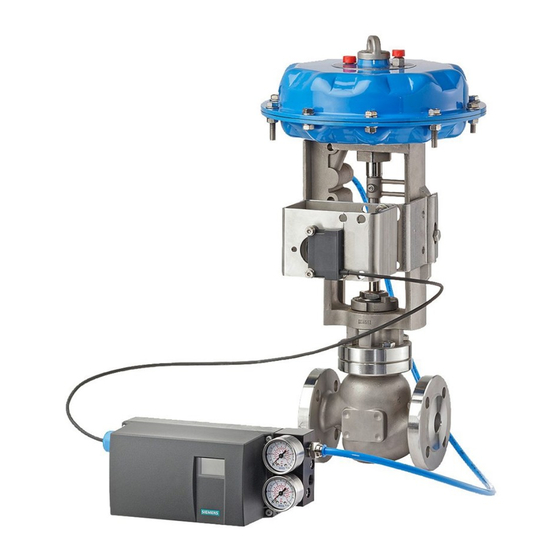
The positioner is used to move and control pneumatic actuators. The positioner works electropneumatically, using compressed air as auxiliary power. The positioner is used to control valves, for example, with: ● Linear actuator ● Part-turn actuator VDI/VDE 3845 SIPART PS2 with and without HART Operating Instructions, 02/2016, A5E00074631-AB... - Page 22 Figure 3-1 Positioner attached to a single-acting linear actuator ① Part-turn actuator ② Pressure gauge block, double-acting ③ Double-acting positioner in Makrolon enclosure Figure 3-2 Positioner attached to double-acting part-turn actuator SIPART PS2 with and without HART Operating Instructions, 02/2016, A5E00074631-AB...
- Page 23 Positioner in flameproof aluminum enclosure attached to linear actuator ① Part-turn actuator ② Double-acting positioner in flameproof aluminum enclosure ③ Pressure gauge block, double-acting Figure 3-4 Positioner in flameproof aluminum enclosure attached to part-turn actuator SIPART PS2 with and without HART Operating Instructions, 02/2016, A5E00074631-AB...
-
Page 24: Nameplate Layout
FM/CSA marking for hazardous area ② ④ ATEX/IECEx marking for hazardous area Permitted ambient temperature for the hazardous area of the corresponding temperature class Figure 3-6 Ex nameplate layout, example SIPART PS2 with and without HART Operating Instructions, 02/2016, A5E00074631-AB... -
Page 25: Explanation Of Ex Information
① ④ Category for operating range Maximum surface temperature (tempera- ture class) ② ⑤ Type of protection Device protection level ③ Group (gas, dust) Figure 3-7 Explanation of Ex information SIPART PS2 with and without HART Operating Instructions, 02/2016, A5E00074631-AB... -
Page 26: Device Components
Restrictor Y2 for double-acting actuators Purging air selector ⑨ Exhaust air outlet with a sound absorber for double-acting actuators only possible when positioner is open Figure 3-8 View of positioner with cover open SIPART PS2 with and without HART Operating Instructions, 02/2016, A5E00074631-AB... -
Page 27: Basic Electronics
Figure 3-9 View of positioner in flameproof enclosure, cover opened 3.3.2 Basic electronics Figure 3-10 Basic electronics, schematic representation The basic electronics contains: ● CPU ● Memory ● Analog-to-digital converter SIPART PS2 with and without HART Operating Instructions, 02/2016, A5E00074631-AB... -
Page 28: Mode Of Operation
In case of medium control deviations, valves are controlled using pulse-length modulated pulses. This takes place in the so-called slow step zone. SIPART PS2 with and without HART Operating Instructions, 02/2016, A5E00074631-AB... - Page 29 AMS. By comparing the old values with the current ones, you can draw conclusions about the wear and tear of the valve. You can use the diagnostics function for this. SIPART PS2 with and without HART Operating Instructions, 02/2016, A5E00074631-AB...
-
Page 30: Block Circuit Diagram For Single-Acting Or Double-Acting Actuators
Pneumatic actuator (double-acting) Figure 3-12 Block circuit diagram for the electropneumatic positioner, functional diagram Note Alarm module and SIA module ⑤ ⑥ Alarm module and SIA module can only be alternatively used. SIPART PS2 with and without HART Operating Instructions, 02/2016, A5E00074631-AB... -
Page 31: Mode Of Operation Of The Hart Function
Communication takes place as frequency modulation on the existing signal lines for the setpoint of 4 to 20 mA. The positioner is integrated into the following parameter assignment tools: ● HART communicator ● PDM (Process Device Manager) ● AMS (Asset Management System) SIPART PS2 with and without HART Operating Instructions, 02/2016, A5E00074631-AB... -
Page 32: Hart System Configuration
● PC with HART modem, on which appropriate software is installed, e.g. SIMATIC PDM (load 230 ... 500 Ω) ● Control system which can communicate via the HART protocol, e.g. SIMATIC PCS7 Figure 3-13 Typical system configurations SIPART PS2 with and without HART Operating Instructions, 02/2016, A5E00074631-AB... -
Page 33: Simatic Pdm
● set ● modified ● saved ● diagnosed ● checked for plausibility ● managed ● simulated Additional information on SIMATIC PDM can be found at SIMATIC PDM instructions and manuals (https://support.industry.siemens.com/cs/products?dtp=Manual&pnid=16983&lc=en-WW). SIPART PS2 with and without HART Operating Instructions, 02/2016, A5E00074631-AB... - Page 34 Description 3.4 Mode of operation SIPART PS2 with and without HART Operating Instructions, 02/2016, A5E00074631-AB...
-
Page 35: Installing/Mounting
• Only use original accessories or original spare parts. • Observe all relevant installation and safety instructions described in the instructions for the device or enclosed with the accessory or spare part. SIPART PS2 with and without HART Operating Instructions, 02/2016, A5E00074631-AB... - Page 36 • Use the customary water separators and filters. An additional dryer is required in extreme cases. • Use dryers, especially if you operate the positioner at low ambient temperatures. SIPART PS2 with and without HART Operating Instructions, 02/2016, A5E00074631-AB...
- Page 37 • To avoid damage to the device, the NPT adapter must be held in place while the NPT gland is screwed into the NPT adapter. Refer to the section "Technical specifications > Construction (Page 245)" for the torque value. SIPART PS2 with and without HART Operating Instructions, 02/2016, A5E00074631-AB...
-
Page 38: Proper Mounting
There are linear actuators for standard mounting in accordance with IEC 60534 and for integrated mounting. Use the reduced mounting kit 6DR4004-8VK for actuators with integrated mounting. Integrated mounting is not possible with flameproof stainless steel enclosure (6DR5..6). SIPART PS2 with and without HART Operating Instructions, 02/2016, A5E00074631-AB... - Page 39 ⑪ Washer • ⑩ Spring lock washer • ⑦ Yoke with Two U–bolts • columns ⑳ Four hexagon nuts • ⑪ Washer • ⑩ Spring lock washer • SIPART PS2 with and without HART Operating Instructions, 02/2016, A5E00074631-AB...
- Page 40 M6 - DIN 934–A4 ⑲ Square nut M6 - DIN 557–A4 ⑳ Hexagon nut M8 - DIN 934–A4 The serial numbers refer to the images of the description of the installation steps below. SIPART PS2 with and without HART Operating Instructions, 02/2016, A5E00074631-AB...
- Page 41 If you need the value of actuator travel after initialization in mm: ensure that the configured stroke value matches the value of the "3.YWAY" parameter. SIPART PS2 with and without HART Operating Instructions, 02/2016, A5E00074631-AB...
- Page 42 Use 2 hexagon bolts ⑩ ⑪ 2 spring lock washers and 2 flat washers for this purpose. Figure 4-4 Installation with mounting bracket SIPART PS2 with and without HART Operating Instructions, 02/2016, A5E00074631-AB...
- Page 43 2. Orient yourself by the lever scale of the actuator. 3. If symmetrical mounting is not possible, you must always ensure that the horizontal lever position is maintained within the range of stroke. SIPART PS2 with and without HART Operating Instructions, 02/2016, A5E00074631-AB...
-
Page 44: Mounting The Part-Turn Actuator
Tighten the mount using the hexagon bolts and lock washers ⑤ ⑤ 2. Stick the pointer mark on the mount. Position the pointer mark at the center of the centering hole. SIPART PS2 with and without HART Operating Instructions, 02/2016, A5E00074631-AB... - Page 45 Coupling wheel, flameproof enclosure ② ② 4. Place the carrier on the stump of the actuator shaft. Tighten the carrier using the ⑨ ⑩ socket cap screw and the washer SIPART PS2 with and without HART Operating Instructions, 02/2016, A5E00074631-AB...
- Page 46 For actuators which close in the clockwise direction, use the pin on which the recess has a V shape (B). For actuators which open in the clockwise direction, use the pin on which the recess has a rectangular shape (A). Orientation of mount SIPART PS2 with and without HART Operating Instructions, 02/2016, A5E00074631-AB...
- Page 47 10.After commissioning, drive the positioner to the end position. ④ 11. Stick the scale with the direction of rotation or the swivel range on the coupling wheel ① . The stickers with scale are self-adhesive. SIPART PS2 with and without HART Operating Instructions, 02/2016, A5E00074631-AB...
- Page 48 Adhesive label with scale, flameproof enclosure H = height of shaft butt ① Fixing level of positioner on mount ② Part-turn actuator Figure 4-6 Dimensions of mount in accordance with VDI/VDE 3845 (depends on actuator) SIPART PS2 with and without HART Operating Instructions, 02/2016, A5E00074631-AB...
-
Page 49: Using The Positioner In A Humid Environment
● Gland with sealing ring, e.g. FESTO: CK - 1 / 4-PK-6 ● Approximately 20 to 30 cm plastic hose, e.g. FESTO: PUN - 8 x 1.25 SW ● Cable tie; the number and the length depend on the local conditions. SIPART PS2 with and without HART Operating Instructions, 02/2016, A5E00074631-AB... -
Page 50: Positioners Subjected To Fast Acceleration Or Strong Vibration
If you use the accessory part "NCS sensor for contactless position measurement" or a built- in internal NCS module, the locking and fixing measures described in this section are not necessary. SIPART PS2 with and without HART Operating Instructions, 02/2016, A5E00074631-AB... - Page 51 Friction clutch latch ③ ⑧ Neutral position Locking friction clutch ④ ⑨ Locking transmission ratio to 90° Release friction clutch ⑤ Transmission ratio selector Figure 4-8 Locking friction clutch and transmission ratio SIPART PS2 with and without HART Operating Instructions, 02/2016, A5E00074631-AB...
- Page 52 ⑦ 5. Use the screwdriver to turn the friction clutch gear latch anticlockwise until it engages. ⑥ The friction clutch is fixed (does not apply to device version "Flameproof enclosure"). SIPART PS2 with and without HART Operating Instructions, 02/2016, A5E00074631-AB...
-
Page 53: External Position Detection
The EMC filter module is used for the controller unit whenever an external position detection system is used instead of the internal position sensor. An external position detection system is, for example, a potentiometer with a 10 kΩ resistance or an NCS sensor. SIPART PS2 with and without HART Operating Instructions, 02/2016, A5E00074631-AB... -
Page 54: Installing Option Modules
The following option modules are available for the positioner in the standard and intrinsically safe version: ● Position feedback module ● Alarm module ● SIA module ● Mechanical limit switch module ● Internal NCS module ● EMC filter module SIPART PS2 with and without HART Operating Instructions, 02/2016, A5E00074631-AB... - Page 55 ⑥ ⑯ Ribbon cable/connector for position feedback Insulating cover, yellow module ⑦ ⑰ Basic electronics Special screw ⑧ ⑱ Alarm module Friction clutch adjustment wheel SIPART PS2 with and without HART Operating Instructions, 02/2016, A5E00074631-AB...
- Page 56 • Proceed as described here in order to avoid premature wear of the base plate and valve. ② Carefully tighten both fixing screws in a clockwise direction. 6. Continue to assemble the positioner by executing steps 3 to 1 in reverse order. SIPART PS2 with and without HART Operating Instructions, 02/2016, A5E00074631-AB...
-
Page 57: Installing The Optional Modules In The "Flameproof Enclosure" Version
• You must install an ignition trap if you use a "conduit piping system". The maximum distance between the ignition trap and the positioner enclosure is 46 cm or 18". SIPART PS2 with and without HART Operating Instructions, 02/2016, A5E00074631-AB... - Page 58 Adjustment wheel for external friction clutch ⑦ ⑲ Basic electronics Feedback shaft ⑧ ⑳ Alarm module Fixing screws adapter ⑨ Position feedback module Safety catch ⑩ Nameplate Ring gear ⑪ Adapter Enclosure SIPART PS2 with and without HART Operating Instructions, 02/2016, A5E00074631-AB...
- Page 59 ① ② 8. Remove the module cover . Unlatch both screws using a screwdriver. 9. Install the optional modules as described in the corresponding sections for the individual optional modules. SIPART PS2 with and without HART Operating Instructions, 02/2016, A5E00074631-AB...
- Page 60 13.Once you have completed all previous steps successfully, continue by performing steps 4 to 1 in reverse order. SIPART PS2 with and without HART Operating Instructions, 02/2016, A5E00074631-AB...
-
Page 61: Position Feedback Module
1. Slide the position feedback module up to the endstop in the lower bay of the rack. 2. Connect the module to the basic electronics. For this purpose, use the 6-pin flat ribbon cable provided. SIPART PS2 with and without HART Operating Instructions, 02/2016, A5E00074631-AB... -
Page 62: Alarm Module
Configure the suitable settings on parameter "BIN2". Device features Figure 4-12 Alarm module SIPART PS2 with and without HART Operating Instructions, 02/2016, A5E00074631-AB... -
Page 63: Slit Initiator Alarm Module (Sia)
● The other two binary outputs are used to signal the two limits L1 and L2 which can be adjusted mechanically using slotted initiators. Both these binary outputs are electrically independent from the remaining electronic unit. SIPART PS2 with and without HART Operating Instructions, 02/2016, A5E00074631-AB... - Page 64 5. Insert the SIA module from the top up to the upper printed circuit board guide of the rack. 6. Slide the SIA module in the printed circuit board of the rack approximately 3 mm to the right. SIPART PS2 with and without HART Operating Instructions, 02/2016, A5E00074631-AB...
- Page 65 2 / Ex from Pepperl + Fuchs. 1. Connect the display device to the following terminals of the SIA module: – 41 and 42 – 51 and 52 2. Read the switch status of slotted initiators. SIPART PS2 with and without HART Operating Instructions, 02/2016, A5E00074631-AB...
-
Page 66: Mechanical Limit Switch Module
• Move the actuator to and fro while simultaneously holding the actuating disks ⑤ 4.7.5 Mechanical limit switch module Requirement You are familiar with the procedure described in the section "Installing optional modules in the standard and intrinsically safe version (Page 54)". SIPART PS2 with and without HART Operating Instructions, 02/2016, A5E00074631-AB... - Page 67 The recesses of the insulating cover must fit in the corresponding webs of the container wall. SIPART PS2 with and without HART Operating Instructions, 02/2016, A5E00074631-AB...
- Page 68 You can achieve an easier and finer adjustment by reducing stiction temporarily. ④ • Move the actuator to and fro while simultaneously holding the actuating disks ⑤ SIPART PS2 with and without HART Operating Instructions, 02/2016, A5E00074631-AB...
-
Page 69: Internal Ncs Module 6Dr4004-5L/-5Le
– SIA module – Mechanical limit switch module – Internal NCS module ● The positioner is mounted, or is to be mounted, directly on the valve using the positioner shaft. SIPART PS2 with and without HART Operating Instructions, 02/2016, A5E00074631-AB... - Page 70 2 Nm. 6. Press the adjustment wheel of the magnet clamp (F) firmly onto the special screw (E) of the friction clutch until you clearly hear it click into place. SIPART PS2 with and without HART Operating Instructions, 02/2016, A5E00074631-AB...
- Page 71 Affix the selected labels on the installed module cover as per the standard version. 17.Proceed with the corresponding steps in the section General information on installing option modules (Page 54). SIPART PS2 with and without HART Operating Instructions, 02/2016, A5E00074631-AB...
-
Page 72: Emc Filter Module
● Any already installed optional module has been removed. A description of how to remove the module cover and install the optional modules is provided in the section "General information on installing option modules (Page 54)" SIPART PS2 with and without HART Operating Instructions, 02/2016, A5E00074631-AB... - Page 73 ⑤ 7. Fit the basic electronics back into the positioner. ④ 8. Insert the ribbon cable connector of the EMC filter module onto the positioner basic electronics. SIPART PS2 with and without HART Operating Instructions, 02/2016, A5E00074631-AB...
- Page 74 9. Fasten the module cover. Make sure that the ribbon cable is not trapped. 10.Proceed with the corresponding steps in the section "General information on installing option modules (Page 54)". SIPART PS2 with and without HART Operating Instructions, 02/2016, A5E00074631-AB...
- Page 75 Installing/mounting 4.7 Installing option modules SIPART PS2 with and without HART Operating Instructions, 02/2016, A5E00074631-AB...
-
Page 76: Accessories
Fixing the pressure gauge block The pressure gauge block is fixed onto the lateral pneumatic connection of the positioner using the screws provided. Use the provided O-rings as sealing elements. SIPART PS2 with and without HART Operating Instructions, 02/2016, A5E00074631-AB... -
Page 77: Connection
• Circuits of limited energy may also be connected in the energized state in hazardous areas. • Exceptions for type of protection "Non-sparking nA" (Zone 2) are regulated in the relevant certificate SIPART PS2 with and without HART Operating Instructions, 02/2016, A5E00074631-AB... - Page 78 • Tighten the cable glands in accordance with the torques specified in Chapter "Technical data (Page 243)". • When replacing cable glands use only cable glands of the same type. • After installation check that the cables are seated firmly. SIPART PS2 with and without HART Operating Instructions, 02/2016, A5E00074631-AB...
- Page 79 • In the NPT version, the positioner is delivered with a coupling. When inserting a counter piece in the coupling, ensure that the maximum permissible torque of 10 Nm is not exceeded. SIPART PS2 with and without HART Operating Instructions, 02/2016, A5E00074631-AB...
- Page 80 Note that this protection is effective only if you connect at least one of these bushes to the earthed control valves through electrically conductive (bare) attachments. SIPART PS2 with and without HART Operating Instructions, 02/2016, A5E00074631-AB...
-
Page 81: Electrical Wiring
Figure 5-1 Base plate Electrical wiring ① ④ Non-hazardous area Binary input 1 ② ⑤ Hazardous area Signal source ③ ⑥ Basic electronics HART communicator Figure 5-2 Device version 2-wire SIPART PS2 with and without HART Operating Instructions, 02/2016, A5E00074631-AB... - Page 82 ⑤ Non-hazardous area Power source ② ⑥ Hazardous area Signal source ③ ⑦ Basic electronics HART communicator ④ Binary input 1 Figure 5-4 Device version 2-/3-/4-wire, with wiring type 3-wire SIPART PS2 with and without HART Operating Instructions, 02/2016, A5E00074631-AB...
- Page 83 ⑤ Non-hazardous area Power source ② ⑥ Hazardous area Signal source ③ ⑦ Basic electronics HART communicator ④ Binary input 1 Figure 5-5 Device version 2-/3-/4-wire, with wiring type 4-wire SIPART PS2 with and without HART Operating Instructions, 02/2016, A5E00074631-AB...
-
Page 84: Connection Diagram Split Range
Binary input 2 ④ ⑨ Travel range 1 Total travel range Iy ⑤ ⑩ Binary input 1 Signal source ⑪ Power source Figure 5-6 Series connection of two positioners, e.g., split range SIPART PS2 with and without HART Operating Instructions, 02/2016, A5E00074631-AB... -
Page 85: Wiring Ncs Sensor To Emc Filter Module
Four-pole NCS cable ⑤ ⑪ Ground: Brown Non Contacting Sensor (NCS) ⑥ ⑫ EMC filter module C73451-A430-D23 Cable shielding lug Figure 5-7 Example of connecting the NCS to the EMC filter module SIPART PS2 with and without HART Operating Instructions, 02/2016, A5E00074631-AB... - Page 86 Ensure this state by measuring the ground resistance. If necessary, ensure proper grounding by means of an additional cable from the NCS sensor to ground potential. SIPART PS2 with and without HART Operating Instructions, 02/2016, A5E00074631-AB...
-
Page 87: Connecting The External Position Detection System To The Emc Filter Module
EMC filter module ⑤ ⑫ Basic electronics EMC filter module cable gland ⑥ ⑬ Screw Input signal for positioner ⑦ EMC filter module C73451-A430-D23 Figure 5-8 Connection to positioner SIPART PS2 with and without HART Operating Instructions, 02/2016, A5E00074631-AB... - Page 88 1. Connect the three terminals of the external position detection system to the three ① terminals of the EMC filter module using a cable as shown in the wiring diagram. ⑩ ⑫ 2. Tighten the cable glands SIPART PS2 with and without HART Operating Instructions, 02/2016, A5E00074631-AB...
-
Page 89: Option Modules
Alarm modules 6DR4004-6A and -8A ① ⑤ Non-hazardous area Fault message ② ⑥ Hazardous area Limit ③ ⑦ Alarm module Switching amplifier ④ ⑧ Binary input 2 Switching output Figure 5-9 Alarm module SIPART PS2 with and without HART Operating Instructions, 02/2016, A5E00074631-AB... -
Page 90: Position Feedback Modules 6Dr4004-6J And -8J
Position feedback module 5.2.4.3 SIA modules 6DR4004-6G and -8G ① ④ Non-hazardous area Fault message ② ⑤ Hazardous area Limit ③ ⑥ SIA module Switching amplifier Figure 5-11 SIA module SIPART PS2 with and without HART Operating Instructions, 02/2016, A5E00074631-AB... -
Page 91: Mechanical Limit Switch Modules 6Dr4004-6K And -8K
The mechanical limit switch module 6DR4004-8K is not approved for use for positioners with UL approval. If this information is ignored, the UL approval for the mechanical limit switch module for the positioner becomes invalid. SIPART PS2 with and without HART Operating Instructions, 02/2016, A5E00074631-AB... - Page 92 2. Pull the transparent cover up to the front end stop. 3. Tighten every cable in the corresponding terminal. ② 4. Slide the transparent cover up to the end stop of the basic electronics. SIPART PS2 with and without HART Operating Instructions, 02/2016, A5E00074631-AB...
- Page 93 6. Connect the cables of each switch to the lug of the printed circuit board in pairs. Use the ③ provided cable ties for this purpose. ① Screw ② Cover ③ Cable tie Figure 5-13 Connecting the cables SIPART PS2 with and without HART Operating Instructions, 02/2016, A5E00074631-AB...
-
Page 94: Option Device Version M12 Connector
Table 5- 2 Assignment diagram Alarm output terminal Pole designation 41 (+) 1 - Brown 52 (-) 4 - Black 42 (-) 3 - Blue 51 (+) 2 - White SIPART PS2 with and without HART Operating Instructions, 02/2016, A5E00074631-AB... -
Page 95: 8J (-Z D53)
Table 5- 5 Assignment diagram Alarm output terminal Pole designation 41 (+) 1 - Brown 52 (-) 4 - Black 42 (-) 3 - Blue 51 (+) 2 - White SIPART PS2 with and without HART Operating Instructions, 02/2016, A5E00074631-AB... -
Page 96: Pneumatic Connection
These connections are sealed with screws when the device is delivered. The exhaust air outlet is corrosion-resistant for the blanketing of the pick-up room and the spring chamber with dry instrument air. SIPART PS2 with and without HART Operating Instructions, 02/2016, A5E00074631-AB... -
Page 97: Pneumatic Connection For 6Dr5..5-0E
⑥ Restrictor Y1 Exhaust air outlet ③ ⑦ Actuating pressure Y2 Enclosure ventilation (2x) ④ Supply air PZ *) for double-acting actuators Figure 5-16 Pneumatic connection in the flameproof enclosure SIPART PS2 with and without HART Operating Instructions, 02/2016, A5E00074631-AB... -
Page 98: Reaction To Failure Of Auxiliary Powers
Make sure that the control valve has reached the safety position. If you only interrupt the pneumatic auxiliary power supply to the positioner, the safety position may in some cases only be attained after a certain delay period. SIPART PS2 with and without HART Operating Instructions, 02/2016, A5E00074631-AB... - Page 99 Connection 5.3 Pneumatic connection Figure 5-17 Regulating action of pneumatic connection SIPART PS2 with and without HART Operating Instructions, 02/2016, A5E00074631-AB...
- Page 100 Connection 5.3 Pneumatic connection Overview of positioning effect for fail in place version Figure 5-18 Pneumatic connections for positioning effect with fail in place version SIPART PS2 with and without HART Operating Instructions, 02/2016, A5E00074631-AB...
-
Page 101: Pneumatic Connection
• After installing the pneumatic connections, check the tightness of the entire control valve. See also Reaction to failure of auxiliary powers (Page 98) Changing the operating mode (Page 107) SIPART PS2 with and without HART Operating Instructions, 02/2016, A5E00074631-AB... -
Page 102: Restrictors
Restrictor Y2, only in the version for double-acting actuators ③ Hexagon socket-head screw 2.5 mm Figure 5-19 Restrictors See also Pneumatic connection for 6DR5..5-0E... (Page 97) Sequence of automatic initialization (Page 117) SIPART PS2 with and without HART Operating Instructions, 02/2016, A5E00074631-AB... -
Page 103: Operating
The display has two lines. These two lines are segmented differently. Each element in the upper line has 7 segments, whereas that in the lower line has 14 segments. Contents of the display depend on the selected mode. SIPART PS2 with and without HART Operating Instructions, 02/2016, A5E00074631-AB... - Page 104 ② Setpoint [%] ③ Fault message ① Diagnostics Diagnostics value ② Diagnostics name ③ Diagnostics number See also System messages before initialization (Page 201) Changing the operating mode (Page 107) SIPART PS2 with and without HART Operating Instructions, 02/2016, A5E00074631-AB...
-
Page 105: Buttons
You have to remove the enclosure cover to operate the buttons of the basic device or the "intrinsically safe" version. Note Degree of protection The IP66/NEMA 4x degree of protection is not ensured as long as the positioner is open. SIPART PS2 with and without HART Operating Instructions, 02/2016, A5E00074631-AB... -
Page 106: Firmware Version
You have five operating modes at your disposal to operate the positioner: 1. P-manual mode (as-delivered condition) 2. Configuration and initialization mode 3. Manual mode (MAN) 4. Automatic (AUT) 5. Diagnostics SIPART PS2 with and without HART Operating Instructions, 02/2016, A5E00074631-AB... -
Page 107: Changing The Operating Mode
Changing the operating mode The following picture illustrates the available operating modes and switching between the operating modes. Figure 6-3 Switching between the operating modes See also Display (Page 103) SIPART PS2 with and without HART Operating Instructions, 02/2016, A5E00074631-AB... -
Page 108: Overview Of Configuration
Move to the actuator with the buttons. Switch to "Configuration" mode to adapt the actuator to the positioner. Alarms or position feedbacks can be triggered after initializing the positioner completely. SIPART PS2 with and without HART Operating Instructions, 02/2016, A5E00074631-AB... - Page 109 Automatic is the standard mode. In this mode, the positioner compares the setpoint position with the actual position. The positioner moves the actuator until the control deviation reaches the configurable deadband. An error message is displayed if the deadband cannot be reached. SIPART PS2 with and without HART Operating Instructions, 02/2016, A5E00074631-AB...
-
Page 110: Optimization Of Controller Data
The following special cases are suitable for targeted data optimization: ● Small actuators with travel times < 1 s. ● Operation with boosters, described in section "Operation with boosters (Page 273)" SIPART PS2 with and without HART Operating Instructions, 02/2016, A5E00074631-AB... - Page 111 Too small values can result in overshoots. • Enter a higher value. Too large values result in too slow speeds of shifting near the adjusted status. • Enter a smaller value. SIPART PS2 with and without HART Operating Instructions, 02/2016, A5E00074631-AB...
- Page 112 It is advantageous to use a fixed reference variable to optimize the control data. Therefore, change the deadband of the controller in the '34.DEBA' parameter from "Auto" to a fixed value. SIPART PS2 with and without HART Operating Instructions, 02/2016, A5E00074631-AB...
-
Page 113: Commissioning
• Check prior to commissioning that the cover, cover locks, and cable inlets are assembled in accordance with the directives. Exception: Devices having the type of protection "Intrinsic safety Ex i" may also be opened in energized state in hazardous areas. SIPART PS2 with and without HART Operating Instructions, 02/2016, A5E00074631-AB... - Page 114 If an error message appears, correct operation in the process is no longer guaranteed. • Check the gravity of the error. • Correct the error. • If the error still exists: – Take the device out of operation. – Prevent renewed commissioning. SIPART PS2 with and without HART Operating Instructions, 02/2016, A5E00074631-AB...
-
Page 115: Overview
4. Adjust the positioner as per the respective actuator with the help of the initialization process and by setting the parameters. If required, use the "PRST" parameter to cancel SIPART PS2 with and without HART Operating Instructions, 02/2016, A5E00074631-AB... - Page 116 You can use a suitably configured and activated binary input to protect the configured settings against accidental adjustment. See also Overview of operating modes (Page 106) Positioners subjected to fast acceleration or strong vibration (Page 50) SIPART PS2 with and without HART Operating Instructions, 02/2016, A5E00074631-AB...
-
Page 117: Sequence Of Automatic Initialization
Optimization of the transient response The following structured charts describe the sequence of initialization. The "Up/Down" names indicate the direction of action of actuators. Linear actuator Part-turn actuator Open Closed Closed Open SIPART PS2 with and without HART Operating Instructions, 02/2016, A5E00074631-AB... - Page 118 Commissioning 7.3 Sequence of automatic initialization Sequence of RUN1 This structured chart describes the process to establish the direction of action. SIPART PS2 with and without HART Operating Instructions, 02/2016, A5E00074631-AB...
- Page 119 Sequence of RUN2 for part-turn actuators This structured chart describes the sequence for checking the actuator travel. It also contains information about the sequence for trimming the lower and upper endstops. SIPART PS2 with and without HART Operating Instructions, 02/2016, A5E00074631-AB...
- Page 120 Sequence of RUN2 for linear actuators This structured chart describes the process to determine the actuator travel checks. It also contains information about the sequence for trimming the lower and upper endstops. SIPART PS2 with and without HART Operating Instructions, 02/2016, A5E00074631-AB...
- Page 121 Sequence of RUN3 to RUN5 This structured chart describes: ● Establishing and displaying the travel time/leakage in RUN3 ● Minimization of controller increments in RUN4 ● Optimization of the transient response in RUN5 SIPART PS2 with and without HART Operating Instructions, 02/2016, A5E00074631-AB...
-
Page 122: Purge Air Switching
Figure 7-1 Purge air switch on the pneumatic block; view of the positioner on the pneumatic connection side when the cover is open The factory setting is the "IN" position. SIPART PS2 with and without HART Operating Instructions, 02/2016, A5E00074631-AB... -
Page 123: Commissioning Linear Actuators
"P37.5", and "NOINI" flashes in the bottom line: 2. Connect the actuator and the positioner to the pneumatic lines. 3. Supply the pneumatic auxiliary power to the positioner. SIPART PS2 with and without HART Operating Instructions, 02/2016, A5E00074631-AB... - Page 124 5LE (Page 69)". Requirement: The '1.YFCT' Type of actuator (Page 155) parameter is set. See also Mounting the linear actuator (Page 38) Installing the optional modules in the "flameproof enclosure" version (Page 57) External position detection (Page 53) SIPART PS2 with and without HART Operating Instructions, 02/2016, A5E00074631-AB...
-
Page 125: Automatic Initialization Of Linear Actuators
3. Check whether the value displayed in the "2.YAGL" parameter matches the setting of the transmission ratio selector. If required, change the setting of the transmission ratio selector to 33° or 90°. SIPART PS2 with and without HART Operating Instructions, 02/2016, A5E00074631-AB... - Page 126 The initialization process depends on the actuator used, and takes up to 15 minutes. 7. The following display indicates that the automatic initialization is complete: SIPART PS2 with and without HART Operating Instructions, 02/2016, A5E00074631-AB...
-
Page 127: Manual Initialization Of Linear Actuators
1. The positioner has been prepared for using on linear actuators. 2. The actuator spindle can be moved completely. 3. The displayed potentiometer position is within the permissible range between "P5.0" and "P95.0". SIPART PS2 with and without HART Operating Instructions, 02/2016, A5E00074631-AB... - Page 128 1. On the scale of the lever, read the value marked by the carrier pin. 2. Set the parameter to the read value with the button. 5. Call the "5.INITM" parameter. To do this, press the button twice. The display shows the following: SIPART PS2 with and without HART Operating Instructions, 02/2016, A5E00074631-AB...
- Page 129 5. Then return to "P manual mode" mode. 6. Correct the actuator travel and the position detection. 10.Determine the upper endstop of the actuator spindle. Move the actuator to the desired position using the button. SIPART PS2 with and without HART Operating Instructions, 02/2016, A5E00074631-AB...
- Page 130 2. Exit the "Configuration" mode. To do this, press the button for at least 5 seconds. The software status is displayed. After releasing the button, the positioner is in "P manual mode". The positioner is not initialized. SIPART PS2 with and without HART Operating Instructions, 02/2016, A5E00074631-AB...
-
Page 131: Commissioning Part-Turn Actuators
By simultaneously pressing the buttons, you reach the end position faster. 3. After checking, move the actuator to a central position. This accelerates the initialization process. See also External position detection (Page 53) SIPART PS2 with and without HART Operating Instructions, 02/2016, A5E00074631-AB... -
Page 132: Automatic Initialization Of Part-Turn Actuators
This parameter has already been set to 90° automatically. The display shows the following: 4. Call the "4.INITA" parameter. To do this, briefly press the button. The display shows the following: SIPART PS2 with and without HART Operating Instructions, 02/2016, A5E00074631-AB... - Page 133 The software status is displayed. After releasing the button, the positioner is in "P manual mode". The part-turn actuator is not initialized. See also Sequence of automatic initialization (Page 117) SIPART PS2 with and without HART Operating Instructions, 02/2016, A5E00074631-AB...
-
Page 134: Manual Initialization Of Part-Turn Actuators
2. Set the "YFCT" parameter to "turn". To do this, press . The display shows the following: 3. Call the second parameter "YAGL". To do this, press . The display shows the following: SIPART PS2 with and without HART Operating Instructions, 02/2016, A5E00074631-AB... - Page 135 5. Then return to "P manual mode". 6. Correct the actuator travel and the position detection. 10.Determine the upper endstop of the actuator. Move the actuator to the desired position using the button. SIPART PS2 with and without HART Operating Instructions, 02/2016, A5E00074631-AB...
-
Page 136: Device Replacement
• Optimum adjustment of the positioner as per the mechanical and dynamic properties of the actuator. • Non-deviating position of end stops • Correctness of the maintenance data SIPART PS2 with and without HART Operating Instructions, 02/2016, A5E00074631-AB... - Page 137 5. To prevent interference with the ongoing process, initialize the new positioner on an actuator with a similar stroke or swivel range. Attach the new positioner to this actuator. Initialize the new positioner. 6. Then dismount the new, initialized positioner from this actuator. SIPART PS2 with and without HART Operating Instructions, 02/2016, A5E00074631-AB...
- Page 138 Sequence of automatic initialization (Page 117) Automatic initialization of linear actuators (Page 125) Automatic initialization of part-turn actuators (Page 132) Manual initialization of linear actuators (Page 127) Manual initialization of part-turn actuators (Page 134) SIPART PS2 with and without HART Operating Instructions, 02/2016, A5E00074631-AB...
-
Page 139: Functional Safety
Functional safety in process instrumentation (http://www.siemens.com/SIL) Safety function Depressurizing of the connected actuator is the safety function for the SIPART PS2 positioner. The built-in spring brings the valve to the required safety position. Depending on the direction of action of this spring, the valve is completely opened or closed. - Page 140 SIPART PS2 with and without HART Operating Instructions, 02/2016, A5E00074631-AB...
-
Page 141: Safety Integrity Level (Sil)
SIL 3 60 to 90 % SIL 2 SIL 3 SIL 4 90 to 99 % SIL 3 SIL 4 SIL 4 > 99% SIL 3 SIL 4 SIL 4 SIPART PS2 with and without HART Operating Instructions, 02/2016, A5E00074631-AB... -
Page 142: Settings
● The positioner is blocked against unwanted and unauthorized changes/operation. ● The signal source with 0 mA or the power supply source with 0 V for the SIPART PS2 positioner is generated by a safe system that fulfills SIL 2 for single-channel operation. -
Page 143: Maintenance/Check
Verify the safety function of the entire safety circuit on a regular basis in accordance with IEC 61508/61511. The test intervals are determined in the course of calculations for each safety circuit of a system (PFD SIPART PS2 with and without HART Operating Instructions, 02/2016, A5E00074631-AB... - Page 144 Functional safety 8.6 Maintenance/check SIPART PS2 with and without HART Operating Instructions, 02/2016, A5E00074631-AB...
-
Page 145: Parameter Assignment
● Logbook with time stamp for documentation of all events such as the violation of thresholds. ● Wizards which provide prompting through the relevant parameters during commissioning, the partial stroke test as well as the offline test. SIPART PS2 with and without HART Operating Instructions, 02/2016, A5E00074631-AB... -
Page 146: Configuration Schematic For Parameter Operating Principle
Parameter assignment 9.2 Configuration schematic for parameter operating principle Configuration schematic for parameter operating principle Figure 9-1 Configuration block schematic SIPART PS2 with and without HART Operating Instructions, 02/2016, A5E00074631-AB... -
Page 147: Tabular Overview Of The Parameters
40 | 50 | 60 | 70 | 90 | 110 | 130 (Long lever 90°, range of stroke 40 to 130 4.INITA Initialization (automatic) NOINI | no / ###.# | Strt 5.INITM Initialization (manual) NOINI | no / ###.# | Strt SIPART PS2 with and without HART Operating Instructions, 02/2016, A5E00074631-AB... -
Page 148: Overview Of Application Parameters 6 To 52
● Setpoint preparation ● Actual value preparation ● Binary signal processing ● Tight closing function ● Limit detection Note Factory-set parameter values are printed in bold in the following table. SIPART PS2 with and without HART Operating Instructions, 02/2016, A5E00074631-AB... - Page 149 Rising riSE Falling FALL 39.YCLS Tight closing manipulated variables None Up only Down only Up and down uP do 40.YCDO Low value for tight closing 0.0 ... 0.5 ... 100.0 SIPART PS2 with and without HART Operating Instructions, 02/2016, A5E00074631-AB...
- Page 150 50.PRST Preset Reset all parameters which can be reset by 'Init', 'PArA' and 'diAg'. Reset initialization parameters Init '1.YFCT' to '5.INITM'. Reset parameters '6.SCUR' to '49. PArA LIM'. SIPART PS2 with and without HART Operating Instructions, 02/2016, A5E00074631-AB...
-
Page 151: Overview Of Advanced Diagnostics Parameters A To P
Parameters A to P and their sub-parameters are only displayed when the extended diagnostics has been activated in parameter "'52.XDIAG' Activating for extended diagnostics (Page 174)" with setting "On1", "On2" or "On3". SIPART PS2 with and without HART Operating Instructions, 02/2016, A5E00074631-AB... - Page 152 Limit 0.1 ... 30.0 ... 100.0 C2.FACT1 Factor 1 0.1 ... 1.0 ... 100.0 C3.FACT2 Factor 2 0.1 ... 1.5 ... 100.0 C4.FACT3 Factor 3 0.1 ... 2.0 ... 100.0 SIPART PS2 with and without HART Operating Instructions, 02/2016, A5E00074631-AB...
- Page 153 Threshold 1 -40 ... -25 ... 90 -40 ... 194 H3.LEVL2 Threshold 2 -40 ... -30 ... 90 -40 ... 194 H4.LEVL3 Threshold 3 -40 ... 90 -40 ... 194 SIPART PS2 with and without HART Operating Instructions, 02/2016, A5E00074631-AB...
- Page 154 Status of monitoring of position average value IdLE / rEF / ###.# / Strt P3.LEVL1 Threshold 1 0.1 ... 2.0 ... 100.0 P4.LEVL2 Threshold 2 0.1 ... 5.0 ... 100.0 P5.LEVL3 Threshold 3 0.1 ... 10.0 ... 100.0 SIPART PS2 with and without HART Operating Instructions, 02/2016, A5E00074631-AB...
-
Page 155: Description Of Parameters
NCS module. No limitations apply to the internal NCS module. In the case of actuators with inverted direction of action, use the settings with the minus sign, e.g. -turn. SIPART PS2 with and without HART Operating Instructions, 02/2016, A5E00074631-AB... -
Page 156: Yagl' Rated Angle Of Rotation Of Feedback
The following is applicable: • 33°: Strokes ≤ 20 mm • 90°: Strokes 25 ... 35 mm • 90°: Strokes > 40 ... 130 mm SIPART PS2 with and without HART Operating Instructions, 02/2016, A5E00074631-AB... -
Page 157: Yway' Range Of Stroke
'3.YWAY' is only displayed if '1.YFCT' is set to 'WAY'/'-WAY' or 'ncSLL'/'-ncLL'. Factory setting: See also '1.YFCT' Type of actuator (Page 155) SIPART PS2 with and without HART Operating Instructions, 02/2016, A5E00074631-AB... -
Page 158: Inita' Initialization (Automatically)
"5.INITM" values are set, it is possible to reset the positioner to the non-initialized status. To do this, press the button for at least 5 seconds. Factory setting: NOINI SIPART PS2 with and without HART Operating Instructions, 02/2016, A5E00074631-AB... -
Page 159: Application Parameters 6 To 52
Application parameters 6 to 52 9.4.2.1 '6.SCUR' Current range of setpoint Requirement: • You have a SIPART PS2 in version "2-, 3-, 4-wire". • Positioner is connected in accordance with the connection graphics for 2/3/4-wire systems shown in section "Electrical wiring (Page 81)". -
Page 160: Spra' Setpoint Split Range Start / '9.Spre' Setpoint Split Range End
• rising/falling • falling/rising • falling/falling • rising/rising Factory setting: With "SPRA": 0.0 With "SPRE": 100.0 Figure 9-2 Example: Split range operation with two positioners SIPART PS2 with and without HART Operating Instructions, 02/2016, A5E00074631-AB... -
Page 161: Tsup' Setpoint Ramp Up / '11.Tsdo' Setpoint Ramp Down
Valve characteristics Set with parameter value Linear Equal percentage 1:25 1-25 Equal percentage 1:33 1-33 Equal percentage 1:50 1-50 Inverse equal percentage 25:1 n1-25 Inverse equal percentage 33:1 n1-33 SIPART PS2 with and without HART Operating Instructions, 02/2016, A5E00074631-AB... -
Page 162: Sl0
Input of the setpoint turning points is only possible if the "'12.SFCT' Setpoint function (Page 161)" parameter is set to "FrEE". You can only enter one monotone rising characteristic curve and two consecutive interpolation points must differ by at least 0.2%. SIPART PS2 with and without HART Operating Instructions, 02/2016, A5E00074631-AB... -
Page 163: Deba' Deadband Of Closed-Loop Controller
See the figure in the description of the '37.YNRM' Standardization of manipulated variable (Page 164) parameter. Factory setting: When 'YA': 0.0 When 'YE': 100.0 Note 'YE' must always be set larger than 'YA'. SIPART PS2 with and without HART Operating Instructions, 02/2016, A5E00074631-AB... -
Page 164: Ynrm' Standardization Of Manipulated Variable
'YA' and 'YE' parameters; see the following figure. Factory setting: MPOS Figure 9-3 YNRM = MPOS or YNRM = FLoW; default: YA = 0 % and YE = 100 % SIPART PS2 with and without HART Operating Instructions, 02/2016, A5E00074631-AB... -
Page 165: Ydir' Direction Of Manipulated Variable For Display And Position Feedback
Purpose: This parameter is used to set the direction of action of the display and the position feedback I . The direction can be rising or falling. Factory setting: riSE SIPART PS2 with and without HART Operating Instructions, 02/2016, A5E00074631-AB... -
Page 166: Ycls' Tight Closing With Manipulated Variable
The "YCDO" and "YCUP" parameters are independent of the values set in the "'7.SDIR' Setpoint direction (Page 159)" and "'38.YDIR' Direction of manipulated variable for display and position feedback (Page 165)" parameters. SIPART PS2 with and without HART Operating Instructions, 02/2016, A5E00074631-AB... -
Page 167: 42.Bin1' / '43.Bin2' Function Binary Input
If the binary input is activated, the actuator uses the value defined by the "'35.YA' Start of manipulated variable limit / '36.YE' End of manipulated variable limit (Page 163)" parameter for controlling in "Automatic" mode. SIPART PS2 with and without HART Operating Instructions, 02/2016, A5E00074631-AB... -
Page 168: Afct' Alarm Function
The direction of action of the binary outputs can be adjusted from "High active" to "Low active" for the next system. Factory setting: SIPART PS2 with and without HART Operating Instructions, 02/2016, A5E00074631-AB... - Page 169 (Page 174)" with setting "On3", then the alarms are not output through the alarm module. Alarm A1 is output with setting "On2". However, notification via the communication interface is possible at any time. SIPART PS2 with and without HART Operating Instructions, 02/2016, A5E00074631-AB...
-
Page 170: 45.A1' / '46.A2' Response Threshold Of Alarms
Alarm function (Page 168)" parameter, the alarm is triggered upon an upward violation (Max) or downward violation (Min) of this re- sponse threshold. Factory setting: With "A1": 10.0 With "A2": 90.0 SIPART PS2 with and without HART Operating Instructions, 02/2016, A5E00074631-AB... -
Page 171: Fct' Function Fault Message
The corresponding response threshold is specified in the '49. LIM' parameter. When the configured time is exceeded, the fault message output is set. Factory setting: Auto SIPART PS2 with and without HART Operating Instructions, 02/2016, A5E00074631-AB... -
Page 172: Lim' Response Threshold Of Fault Message 'Control Deviation
'YCUP: > 100 %'. This functionality is especially advantageous for valves with lining. For long-term monitoring of the end stop positions, we recommend activating the 'F. ZERO' and OPEN' parameters. SIPART PS2 with and without HART Operating Instructions, 02/2016, A5E00074631-AB... -
Page 173: 50.Prst' Preset
To do this, use the 'ALL' setting. Factory setting: See also Display of diagnostics values (Page 207) SIPART PS2 with and without HART Operating Instructions, 02/2016, A5E00074631-AB... -
Page 174: Pneum' Fail In Place
The message is cancelled if, for example: • The counter is reset. • The threshold is set to a new value. • The device is re-initialized at the upper and lower endstops. • Monitoring is deactivated. SIPART PS2 with and without HART Operating Instructions, 02/2016, A5E00074631-AB... - Page 175 Display of a threshold 3 message (maintenance alarm) The factory setting is 'OFF'. See also Partial stroke test 'A.\\PST' (Page 176) Monitoring the position average value 'P.\\PAVG' (Page 197) Overview of error codes (Page 226) SIPART PS2 with and without HART Operating Instructions, 02/2016, A5E00074631-AB...
-
Page 176: Extended Diagnostics Parameters A To P
The actuator moves during the partial stroke test from the start position to the target position. The target position is determined from the interaction between start position (A1.STPOS), stroke height (A3.STRKH) and stroke direction (A4.STRKD). Factory setting: 100.0 SIPART PS2 with and without HART Operating Instructions, 02/2016, A5E00074631-AB... - Page 177 • After reaching the lower target position, the actuator moves back to the start position. Formula (do): Lower target position = Start position (A1.STPOS) ± Start toler- ance (A2.STTOL) + Stroke height (A3.STRKH) SIPART PS2 with and without HART Operating Instructions, 02/2016, A5E00074631-AB...
-
Page 178: A6.Rprt Ramp Rate 0.1
Example: Setting '10.0' means that the partial stroke test is run with 10% stroke per second. Factory setting: SIPART PS2 with and without HART Operating Instructions, 02/2016, A5E00074631-AB... -
Page 179: A7.Flbh Behavior After Failed Pst Auto / Hold / Airin / Airou
'C 1.2', where 'C' stands for 'calculated'. The average travel time can be used as a reference stroke time. However, it merely represents a rough guideline value. SIPART PS2 with and without HART Operating Instructions, 02/2016, A5E00074631-AB... -
Page 180: Aa.fact1 - Factor 1
'A9.PSTIN'. The threshold 2 message is displayed when threshold 2 is ex- ceeded. The process to activate and display this message is de- scribed in the 'XDIAG' parameter. Factory setting: SIPART PS2 with and without HART Operating Instructions, 02/2016, A5E00074631-AB... -
Page 181: Monitoring Of Dynamic Control Valve Behavior 'B.\\Devi
The current value is displayed in Diagnostic value '15.DEVI - Gen- eral control valve fault' (Page 215). The positioner triggers a mes- sage if the current value exceeds one of the three thresholds. Factory setting: SIPART PS2 with and without HART Operating Instructions, 02/2016, A5E00074631-AB... -
Page 182: B3.Fact1 - Factor 1
This message is only output if threshold 2 or 3 is not ex- ceeded at the same time. The process to activate and display this message is described in the 'XDIAG' parameter. Factory setting: SIPART PS2 with and without HART Operating Instructions, 02/2016, A5E00074631-AB... -
Page 183: Monitoring Pneumatic Leakage 'C.\\Leak
Please note that this monitoring only delivers results in the case of an activated tight closing function and a setpoint with the following values: Lower value for tight closing (YCDO) +5 % up to upper value for tight closing (YCUP) -5 % SIPART PS2 with and without HART Operating Instructions, 02/2016, A5E00074631-AB... - Page 184 Define the limit of the leakage indicator accordingly. The positioner triggers a message if the current value exceeds one of the three thresholds. How to set the three thresholds is de- scribed below. Factory setting: 30.0 SIPART PS2 with and without HART Operating Instructions, 02/2016, A5E00074631-AB...
-
Page 185: Monitoring The Stiction (Slipstick) 'D.\\Stic
STIC - Monitoring the stiction (slipstick) Requirement: The '52.XDIAG' Activating for extended diagnostics (Page 174) parameter is set to 'On1', 'On2' or 'On3'. Possible settings: • OFF • On SIPART PS2 with and without HART Operating Instructions, 02/2016, A5E00074631-AB... - Page 186 'd1.LIMIT' and 'd2.FACT1'. The threshold 1 message is displayed when threshold 1 is ex- ceeded. The process to activate and display this message is de- scribed in the 'XDIAG' parameter. Factory setting: SIPART PS2 with and without HART Operating Instructions, 02/2016, A5E00074631-AB...
-
Page 187: Monitoring The Deadband 'E.\\Deba
The current value is displayed in Diagnostic value '26.DBUP - Deadband UP' / '27.DBDN - Deadband DOWN' (Page 220). The positioner triggers a message if the current value exceeds the threshold. Factory setting: SIPART PS2 with and without HART Operating Instructions, 02/2016, A5E00074631-AB... -
Page 188: Monitoring The Lower Endstop 'F.\\Zero
'On1', 'On2' or 'On3'. The '39.YCLS' Tight closing with manipulated variable (Page 166) parameter is set to 'do' or 'uP do'. Possible settings: • OFF • On SIPART PS2 with and without HART Operating Instructions, 02/2016, A5E00074631-AB... - Page 189 The positioner triggers a message if the difference between the lower endstop and the initialization value undershoots threshold 3. The process to activate and display this message is described in the 'XDIAG' parameter. Factory setting: SIPART PS2 with and without HART Operating Instructions, 02/2016, A5E00074631-AB...
-
Page 190: Monitoring The Upper Endstop 'G.\\Open
The positioner triggers a message if the difference between the upper endstop and the initialization value overshoots threshold 1. The process to activate and display this message is described in the 'XDIAG' parameter. Factory setting: SIPART PS2 with and without HART Operating Instructions, 02/2016, A5E00074631-AB... -
Page 191: Monitoring The Low Limit Temperature 'H.\\Tmin
The value is displayed in Diagnostic value '31.TMIN - Minimum temperature' / '32.TMAX - Maximum temperature' (Page 221). The positioner triggers a message if the current value undershoots one of the three thresholds. Factory setting: SIPART PS2 with and without HART Operating Instructions, 02/2016, A5E00074631-AB... - Page 192 3. The process to activate and display this message is described in the 'XDIAG' parameter. Factory setting: -40.0C See also '39.YCLS' Tight closing with manipulated variable (Page 166) SIPART PS2 with and without HART Operating Instructions, 02/2016, A5E00074631-AB...
-
Page 193: Monitoring The High Limit Temperature 'J.\\Tmax
The positioner triggers a message if the current temperature inside the enclosure overshoots threshold 1. The process to activate and display this message is described in the 'XDIAG' parameter. Factory setting: 75.0C SIPART PS2 with and without HART Operating Instructions, 02/2016, A5E00074631-AB... -
Page 194: Monitoring The Number Of Total Strokes 'L.\\Strk
This message is only output if threshold 2 or 3 is not exceeded at the same time. Factory setting: SIPART PS2 with and without HART Operating Instructions, 02/2016, A5E00074631-AB... -
Page 195: L1. Limit Limit For Number Of Total Strokes 1
The threshold 1 message is displayed when threshold 1 is ex- ceeded. The process to activate and display this message is de- scribed in the 'XDIAG' parameter. Factory setting: See also Display of diagnostics values (Page 207) SIPART PS2 with and without HART Operating Instructions, 02/2016, A5E00074631-AB... -
Page 196: Monitoring The Number Of Changes In Direction 'O.\\Dchg
'O2.FACT1'. The threshold 1 message is displayed when threshold 1 is exceeded. The pro- cess to activate and display this message is described in the 'XDIAG' parame- ter. Factory setting: SIPART PS2 with and without HART Operating Instructions, 02/2016, A5E00074631-AB... -
Page 197: Monitoring The Position Average Value 'P.\\Pavg
The current value is displayed in Diagnostic value '20.PAVG - Av- erage value of position' (Page 217). The positioner triggers a mes- sage if the current average value of position undershoots one of the three thresholds. Factory setting: SIPART PS2 with and without HART Operating Instructions, 02/2016, A5E00074631-AB... - Page 198 The respective current average value of position is displayed in the Diagnostic value '20.PAVG - Average value of position' (Page 217). If no average value of position has been calculated, 'COMP' is displayed as the diagnostic value. SIPART PS2 with and without HART Operating Instructions, 02/2016, A5E00074631-AB...
-
Page 199: P3.Levl1 - Threshold 1
3. The procedure to activate and display this mes- sage is described in the 'XDIAG' parameter. Factory setting: 10.0 SIPART PS2 with and without HART Operating Instructions, 02/2016, A5E00074631-AB... - Page 200 Parameter assignment 9.4 Description of parameters SIPART PS2 with and without HART Operating Instructions, 02/2016, A5E00074631-AB...
-
Page 201: Alarm, Error, And System Messages
Adjust the effective lever length of linear • actuators as per the measuring range. NOINI Positioner is not initialized. Start initialization. • See also Display (Page 103) SIPART PS2 with and without HART Operating Instructions, 02/2016, A5E00074631-AB... -
Page 202: System Messages During Initialization
• played, and then acknowledge with the key. Terminate the initialization process using • key, switch to the P-manual mode, and correct the actuator travel and the position displacement sensor. SIPART PS2 with and without HART Operating Instructions, 02/2016, A5E00074631-AB... - Page 203 To change the travel time, interrupt the • initialization process using the key. Activate the leakage test using the • key. D nn.n Display of the "Down" travel time Wait until initialization continues in • SIPART PS2 with and without HART Operating Instructions, 02/2016, A5E00074631-AB...
- Page 204 1. Briefly acknowledge using key. display of actuator travel or the actuator FINISH 2. Leave configuration level by long press- angle ing of key. See also System messages before initialization (Page 201) SIPART PS2 with and without HART Operating Instructions, 02/2016, A5E00074631-AB...
-
Page 205: System Messages When Exiting The Configuration Mode
Positioner is not initialized. Start initialization. • nnn.n Actual position [in %] for initial- ized positioner. Flashing decimal point shows communication with a class 2 master. AUTnn Automatic mode (nn = setpoint) SIPART PS2 with and without HART Operating Instructions, 02/2016, A5E00074631-AB... - Page 206 Cyclic partial stroke test. Full stroke test running. Step response test running. MSRT Multi-step response test running. Valve performance test running. LEAKR A leakage test started by com- munication is running. SIPART PS2 with and without HART Operating Instructions, 02/2016, A5E00074631-AB...
-
Page 207: Diagnostics
To do this, press the button for at least 5 seconds. The diagnostic values which can be reset can be found in the table in section Overview of diagnostics values (Page 208). SIPART PS2 with and without HART Operating Instructions, 02/2016, A5E00074631-AB... -
Page 208: Overview Of Diagnostics Values
Days ② DEVI Dynamic control valve behavior OFF / 0.0 ... 100.0 ② ONLK Pneumatic leakage OFF / 0.0 ... 100.0 ② STIC Stiction (slipstick) OFF / 0.0 ... 100.0 SIPART PS2 with and without HART Operating Instructions, 02/2016, A5E00074631-AB... - Page 209 0 ... 4.29E9 ① VEN1R Number of switching cycles of pilot valve 1, resetta- 0 ... 4.29E9 ① VEN2R Number of switching cycles of pilot valve 2, resetta- 0 ... 4.29E9 SIPART PS2 with and without HART Operating Instructions, 02/2016, A5E00074631-AB...
- Page 210 Number of operating hours in the travel range WT90 0 ... 4.29E9 Hours ① WT95 Number of operating hours in the travel range WT95 0 ... 4.29E9 Hours ② Setpoint current 0.0 ... 20.0 SIPART PS2 with and without HART Operating Instructions, 02/2016, A5E00074631-AB...
-
Page 211: Meaning Of The Diagnostics Values
Diagnostic value '6.HOURS - Number of operating hours' Display range: 0 ... 4.29E9 Purpose: The runtime meter is incremented every hour as soon as electric auxiliary power is supplied to the positioner. SIPART PS2 with and without HART Operating Instructions, 02/2016, A5E00074631-AB... -
Page 212: Diagnostic Value '7.Hourr - Resettable Operating Hours Counter
10.2.4.9 Diagnostic value '11.LEAK - Leakage test' Requirement The positioner is initialized and in manual mode (MAN). Display range: • - • 0.0 ... 100.0 SIPART PS2 with and without HART Operating Instructions, 02/2016, A5E00074631-AB... - Page 213 After one minute, the display shows the difference in the actuator position before and after the test. This means: the actuator position has changed by the displayed value in one minute. SIPART PS2 with and without HART Operating Instructions, 02/2016, A5E00074631-AB...
-
Page 214: Diagnostic Value '12.Pst - Monitoring Of Partial Stroke Test
• Strt - Start: A manual partial stroke test is started five seconds after pressing the button. • StoP - Stop: The current partial stroke test is interrupted. 'WAIT' is output in the display. Factory setting: SIPART PS2 with and without HART Operating Instructions, 02/2016, A5E00074631-AB... -
Page 215: Diagnostic Value '13.Prpst' - Time Since Last Partial Stroke Test
This value in percent provides information about the current dy- namically determined deviation from the model response. If the underlying function is deactivated, 'OFF' is displayed. See also Partial stroke test 'A.\\PST' (Page 176) SIPART PS2 with and without HART Operating Instructions, 02/2016, A5E00074631-AB... -
Page 216: Diagnostic Value '16.Onlk - Pneumatic Leakage
• OFF • 0.0 ... 100.0 Purpose: An indication of the current shift of the upper endstop compared to its initialization value. If the underlying function is deactivated, 'OFF' is displayed. SIPART PS2 with and without HART Operating Instructions, 02/2016, A5E00074631-AB... -
Page 217: Diagnostic Value '20.Pavg - Average Value Of Position
• COMP: The comparison average is calculated. The function was started, and the comparison interval is in progress at the moment. SIPART PS2 with and without HART Operating Instructions, 02/2016, A5E00074631-AB... -
Page 218: Diagnostic Value '21.P0 - Potentiometer Value Of Lower Endstop (0%)' / '22.P100 - Potentiometer Value Of Upper Endstop (100%)
Therefore reset the 'P0' and/or 'P100' parameters after the process-dependent thermal expansion has had its complete effect on the control valve. The procedure is described in the following. SIPART PS2 with and without HART Operating Instructions, 02/2016, A5E00074631-AB... -
Page 219: Diagnostic Value '23.Impup - Impulse Length Up' / '24.Impdn - Impulse Length Down
In the case of special applications you can additionally set the smallest impulse lengths in these two parameters. Factory setting: See also Mode of operation (Page 28) Optimization of controller data (Page 110) SIPART PS2 with and without HART Operating Instructions, 02/2016, A5E00074631-AB... -
Page 220: Diagnostic Value '25.Pautp - Pulse Interval
This parameter can be set for special applications. Factory setting: 10.0 See also Mode of operation (Page 28) Optimization of controller data (Page 110) SIPART PS2 with and without HART Operating Instructions, 02/2016, A5E00074631-AB... -
Page 221: Diagnostic Value '30.Temp - Current Temperature
≥ 45 ≥ 60 ≥ 75 ≤ -30 < -15 < 0 < 15 < 30 < 45 < 60 < 75 Operating hours in temperature ranges T1 to T2 SIPART PS2 with and without HART Operating Instructions, 02/2016, A5E00074631-AB... -
Page 222: Diagnostic Value '42.Vent1' / '43.Vent2
Description: Corresponds to the description for Diagnostic value '42.VENT1' / '43.VENT2' (Page 222) referred to the diagnostics parameters 'VEN1R' and 'VEN2R' described here. SIPART PS2 with and without HART Operating Instructions, 02/2016, A5E00074631-AB... -
Page 223: Diagnostic Value '46.Store - Save Maintenance Data
This helps in drawing conclusions about the past operating conditions and especially in assessing the control properties of the control loop and the entire control valve. SIPART PS2 with and without HART Operating Instructions, 02/2016, A5E00074631-AB... -
Page 224: Diagnostic Value '57.Ma - Setpoint Current
If multiple triggers occur at the same time, they are displayed one after the other cyclically. The device status, including all fault messages, can be called up using command "#48" over HART. SIPART PS2 with and without HART Operating Instructions, 02/2016, A5E00074631-AB... - Page 225 Alarm, error, and system messages 10.3 Online diagnostics See also '52.XDIAG' Activating for extended diagnostics (Page 174) Extended diagnostics parameters A to P (Page 176) SIPART PS2 with and without HART Operating Instructions, 02/2016, A5E00074631-AB...
-
Page 226: Overview Of Error Codes
Or increase the PST start tolerance until the actuator (PST start posi- tion) is within the PST start tolerance. Start the partial stroke test again. SIPART PS2 with and without HART Operating Instructions, 02/2016, A5E00074631-AB... - Page 227 A4.STRKD are plausible. parameter values Refer to the corresponding parameter descriptions for additional information about parameters See also Overview of application parameters 6 to 52 (Page 148) SIPART PS2 with and without HART Operating Instructions, 02/2016, A5E00074631-AB...
-
Page 228: Xdiag Parameter
For example, it can be a switch to monitor the packing glands, a temperature switch or a limit switch (e.g. for pressure). Binary input 2 (in the optional alarm module) can be configured in a similar manner. SIPART PS2 with and without HART Operating Instructions, 02/2016, A5E00074631-AB... -
Page 229: Monitoring The Number Of Total Strokes
A limit can therefore be entered for this value ("E1.LEVL3", threshold for deadband monitoring). An error message output is activated when this value is exceeded. SIPART PS2 with and without HART Operating Instructions, 02/2016, A5E00074631-AB... -
Page 230: Partial Stroke Test
15 Monitoring the position average value This fault message appears when a position value calculated after the expiry of a comparison interval deviates from the reference value by more than the configured thresholds. SIPART PS2 with and without HART Operating Instructions, 02/2016, A5E00074631-AB... -
Page 231: Monitoring The Plausibility Of Values For The Partial Stroke Test
Mostly after a specific operation time • See also Remedial measures table 2 (Page 233) Remedial measures table 3 (Page 234) Corrective measures Table 4 (Page 235) Remedial measures table 5 (Page 236) SIPART PS2 with and without HART Operating Instructions, 02/2016, A5E00074631-AB... -
Page 232: Remedial Measures Table 1
Linear actuator: check for the firm- • ness of the lever on the positioning shaft. Correct any other play between the • actuator and the control valve. Fault table 1 SIPART PS2 with and without HART Operating Instructions, 02/2016, A5E00074631-AB... -
Page 233: Remedial Measures Table 2
Fault table 2 See also Repair/Upgrading (Page 241) SIPART PS2 with and without HART Operating Instructions, 02/2016, A5E00074631-AB... -
Page 234: Remedial Measures Table 3
In case of an intact actuator and • mode. tight feed line: Repair or new device Dirt in the pneumatic block See above • • Fault table 3 See also Repair/Upgrading (Page 241) SIPART PS2 with and without HART Operating Instructions, 02/2016, A5E00074631-AB... -
Page 235: Corrective Measures Table 4
(at 20 mA). the feeding controller or system ballast converter output is too low. Select 3/4-wire mode • Error table 4 See also Cleaning of the screens (Page 238) SIPART PS2 with and without HART Operating Instructions, 02/2016, A5E00074631-AB... -
Page 236: Remedial Measures Table 5
For prevention: Install the positioner • terminals may be loosened. on the damping pads. Electrical connecting terminals • and/or electronic components may be knocked out. Fault table 5 See also Repair/Upgrading (Page 241) SIPART PS2 with and without HART Operating Instructions, 02/2016, A5E00074631-AB... -
Page 237: Service And Maintenance
11.1 Basic safety instructions WARNING Impermissible repair of the device • Repair must be carried out by Siemens authorized personnel only. WARNING Impermissible accessories and spare parts Danger of explosion in areas subject to explosion hazard. • Only use original accessories or original spare parts. -
Page 238: Cleaning Of The Screens
If there are dirt particles in the pneumatic auxiliary power supply, they damage the screens and hamper the function of the positioner. Clean the screens as described in the following two chapters. SIPART PS2 with and without HART Operating Instructions, 02/2016, A5E00074631-AB... -
Page 239: Positioners With Makrolon Enclosure 6Dr5
4. Tighten the three screws. Note: With the Makrolon enclosure, the screws are self-tapping. 5. Place the cover and tighten it. 6. Reconnect the pipelines and feed the pneumatic power supply. SIPART PS2 with and without HART Operating Instructions, 02/2016, A5E00074631-AB... -
Page 240: Positioners With Stainless Steel Enclosure 6Dr5
4. Set the "'51.PNEUM' Fail in place (Page 174)" parameter from "Std" to "FIP". 5. Install the enclosure cover. 6. Switch on the supply air PZ again. 7. Initialize the positioner as described in section "Commissioning (Page 113)" SIPART PS2 with and without HART Operating Instructions, 02/2016, A5E00074631-AB... -
Page 241: Repair/Upgrading
Any devices/replacement parts returned without a decontamination declaration will be cleaned at your expense before further processing. The forms can be found on the Internet as well as in the documentation which comes with the device. SIPART PS2 with and without HART Operating Instructions, 02/2016, A5E00074631-AB... -
Page 242: Disposal
Directive 2002/96/EC on waste electronic and electrical equip- ment (WEEE). They can be returned to the supplier within the EC or to a local- ly approved disposal service. Observe the specific regulations valid in your country. SIPART PS2 with and without HART Operating Instructions, 02/2016, A5E00074631-AB... -
Page 243: Technical Data
At ≤ -10 °C (≤ 14 °F) the display refresh rate of the indicator is limited. When using position feedback module, only T4 is permissible. The following applies to order suffix (order code) -Z M40: -40 ... +80 °C (-40 ... +176°F) SIPART PS2 with and without HART Operating Instructions, 02/2016, A5E00074631-AB... -
Page 244: Pneumatic Data
The following applies to fail in place: 3 ... 7 bar (43.5 to 101.5 psi) When using device versions Ex d (6DR5..5-... and 6DR5..6-...), values are reduced by approximately 20%. SIPART PS2 with and without HART Operating Instructions, 02/2016, A5E00074631-AB... -
Page 245: Construction
In Makrolon enclosure 6DR5..0 • Single-acting In aluminum enclosure 6DR5..1 • Single-acting and double-acting In aluminum enclosures 6DR5..3 and 6DR5..5 • Single-acting and double-acting In stainless steel enclosures 6DR5..2 and 6DR5..6 • Torques SIPART PS2 with and without HART Operating Instructions, 02/2016, A5E00074631-AB... - Page 246 Without Ex protection as well as with Ex i: M20x1.5 or ½- Cable gland • 14 NPT With explosion protection Ex d: Ex d certified M20x1.5, ½- 14 NPT or M25x1.5 Connections, pneumatic Female thread G¼ or ¼-18 NPT SIPART PS2 with and without HART Operating Instructions, 02/2016, A5E00074631-AB...
-
Page 247: Controller
3 (good engineering practice SEP) CE conformity The applicable directives and applied standards with their revision levels can be found in the EC declaration of conformity on the Internet. See also Certificates (http://www.siemens.com/processinstrumentation/certificates) SIPART PS2 with and without HART Operating Instructions, 02/2016, A5E00074631-AB... - Page 248 ≤ +80 °C (-40 ≤ T ≤ +176 °F) 6DR5ayb-0cdef-g.Ah-Z M40 • T6: -40 ≤ T ≤ +50 °C (-40 ≤ T ≤ +122 °F) Position feedback module (already fitted or can be retrofitted) SIPART PS2 with and without HART Operating Instructions, 02/2016, A5E00074631-AB...
- Page 249 (c = D or K) -40 ≤ Ta ≤ +80 °C (-40 ≤ Ta ≤ +176 °F) 6DR5ayb-0cdef-g.Ah-Z M40 • with the data (c= D or K) SIPART PS2 with and without HART Operating Instructions, 02/2016, A5E00074631-AB...
-
Page 250: Electrical Data
Without HART • 11 nF "ic": 11 nF With HART • Effective inner inductance L 207 µH "ic": 207 µH Without HART • 310 µH "ic": 310 µH With HART • SIPART PS2 with and without HART Operating Instructions, 02/2016, A5E00074631-AB... - Page 251 I (2 intrinsically safe circuits) HART communication HART version PC parameter assignment SIMATIC PDM; supports all device objects. The software is not included in the scope of software delivery. SIPART PS2 with and without HART Operating Instructions, 02/2016, A5E00074631-AB...
-
Page 252: Technical Data For Natural Gas As Actuator Medium
1) Depending on the actuating pressure and volume of the actuator as well as the frequency of con- trol. The maximum flow rate is 470 Nl/min at a differential pressure of 7 bar. SIPART PS2 with and without HART Operating Instructions, 02/2016, A5E00074631-AB... -
Page 253: Option Modules
Binary input BI2: Terminals 11 and 12, terminals 21 and 22 (jumper) • Galvanically connected with the • basic device Signal status 0 Floating contact, open Signal status 1 Floating contact, closed Contact load 3 V, 5 μA SIPART PS2 with and without HART Operating Instructions, 02/2016, A5E00074631-AB... -
Page 254: Position Feedback Module
[kΩ] ≤ (U [V] - 12 V)/I [mA] Transmission error ≤ 0.3 % Temperature influence ≤ 0.1%/10 K (≤ 0.1%/18 °F) Resolution ≤ 0.1 % Residual ripple ≤ 1 % SIPART PS2 with and without HART Operating Instructions, 02/2016, A5E00074631-AB... -
Page 255: Sia Module
≤ 1 mA (limit activated) ≤ DC 15 V ≤ 64 mW Effective internal capacitance = 41 nF = 41 nF Effective internal inductance = 100 μH = 100 μH SIPART PS2 with and without HART Operating Instructions, 02/2016, A5E00074631-AB... -
Page 256: Mechanical Limit Switch Module
= 750 mW = 100 mA "t": = 30 V = 100 mA Effective internal capacitance = negligibly small = negligibly small Effective internal inductance = negligibly small = negligibly small SIPART PS2 with and without HART Operating Instructions, 02/2016, A5E00074631-AB... - Page 257 DC 3150 V, 2 s Rated condition height Max. 2 000 m mean sea level Use a suitable power supply at an altitude of more than 2 000 m above sea level. SIPART PS2 with and without HART Operating Instructions, 02/2016, A5E00074631-AB...
-
Page 258: Emc Filter Module
Bumping according to IEC 60068- • 2-29 Torque for cable gland nut made of Plastic Metal Stainless steel 2.5 Nm (1.8 ft lb) 4.2 Nm (3.1 ft lb) 4.2 Nm (3.1 ft lb) SIPART PS2 with and without HART Operating Instructions, 02/2016, A5E00074631-AB... -
Page 259: Internal Ncs Modules 6Dr4004-5L And 6Dr4004-5Le
Internal NCS module 6DR4004-5L 6DR4004-5LE 6DR4004-5LE Linearity (after corrections made by ± 1 % ± 1 % ± 1 % positioner) Hysteresis ± 0.2 % ± 0.2 % ± 0.2 % SIPART PS2 with and without HART Operating Instructions, 02/2016, A5E00074631-AB... -
Page 260: External Position Detection System
The required mount must be provided on the actuator- side. Material Makrolon® glass-fiber reinforced polycarbonate (PC) Enclosure • Weight, basic device Approximately 0.9 kg (1.98 lb) Torque for cable gland nut made of plastic 2.5 Nm SIPART PS2 with and without HART Operating Instructions, 02/2016, A5E00074631-AB... -
Page 261: Certificates, Approvals, Explosion Protection For External Position Detection System
Zone 2: II 3 G Ex nA IIC T6/T4 Gc Permissible ambient temperature T4: -40 ... +90 °C (-40 ... +194 °F) T6: -40 ... +60 °C (-40 ... +140 °F) SIPART PS2 with and without HART Operating Instructions, 02/2016, A5E00074631-AB... - Page 262 Technical data 12.8 Option modules SIPART PS2 with and without HART Operating Instructions, 02/2016, A5E00074631-AB...
-
Page 263: Dimension Drawings
44 [1.73] 39 [1.54] 39 [1.54] 14.5 [0.57] 16 [0.63] 16 [0.63] 14.5 [0.57] 96.6 [3.80] 96.6 [3.80] 98.5 [3.88] 103 [4.06] 18.5 [0.73] 22 [0.87] 18.5 [0.73] 18.5 [0.73] SIPART PS2 with and without HART Operating Instructions, 02/2016, A5E00074631-AB... -
Page 264: Terminal Strip For Positioners With Macrolon Enclosure 6Dr5
6DR64.. SITRANS VP160; dimensions with pneumatic connection G¼ or ¼-NPT 13.2 Terminal strip for positioners with Macrolon enclosure 6DR5..0 and aluminum enclosure 6DR5..3 ① Thread depth Figure 13-2 Terminal strip, dimensions in mm (inch) SIPART PS2 with and without HART Operating Instructions, 02/2016, A5E00074631-AB... -
Page 265: Positioner With Flameproof Enclosure
Dimensions of positioner in flameproof enclosure 6DR5..5 6DR5..6 5 [0.2] 60 [2.36] 25.7 [1.01] 21.7 [0.85] 33.5 [1.32] 25 [0.99] 33.5 [1.32] 158.5 [6.24] 160 [6.3] 235.3 [9.26] 227.6 [8.96] SIPART PS2 with and without HART Operating Instructions, 02/2016, A5E00074631-AB... - Page 266 Dimension drawings 13.3 Positioner with flameproof enclosure Dimensions in mm [inch] 6DR5..5 Aluminum enclosure, flameproof; dimensions with pneumatic connection G¼ or ¼- 6DR5..6 Stainless steel enclosure, flameproof SIPART PS2 with and without HART Operating Instructions, 02/2016, A5E00074631-AB...
-
Page 267: Spare Parts / Accessories / Scope Of Delivery
● Makrolon enclosure for single and double-acting actuators ● Aluminum enclosure for single-acting or double-acting actuators ● Stainless steel enclosure for single and double-acting actuators ● Flameproof enclosure for single and double-acting actuators SIPART PS2 with and without HART Operating Instructions, 02/2016, A5E00074631-AB... - Page 268 ● Mounting kits for linear and part-turn actuators For separate mounting of positioner and position sensor ● External position detection system ● NCS sensor for contactless position detection Note The version is identified using a special nameplate. SIPART PS2 with and without HART Operating Instructions, 02/2016, A5E00074631-AB...
-
Page 269: Spare Parts
Manometer 0 to 10 bar, metal, G1/8, 3 units A5E32527731 6DR5... Manometer 0 to 10 bar, stainless steel, G1/8, 3 A5E32527735 6DR5... units Note See Catalog FI 01 "Field devices for process automation" for additives and possible modules". SIPART PS2 with and without HART Operating Instructions, 02/2016, A5E00074631-AB... -
Page 270: Scope Of Delivery Of External Position Detection System
14.6 Scope of delivery EMC filter module Cable glands and adapters The EMC filter module is supplied with various cable glands and adapters. The following diagram shows the different variants. SIPART PS2 with and without HART Operating Instructions, 02/2016, A5E00074631-AB... - Page 271 ④ Cable gland for connection thread, gray ④ Cable gland for connection thread, blue ④ Sealing set for ④ Sealing set plug for Screw for plastic Oval head screw M3x6 SIPART PS2 with and without HART Operating Instructions, 02/2016, A5E00074631-AB...
-
Page 272: Accessories
For accessories, refer to Catalog FI 01 "Field devices for process automation", for example: ● Option modules ● NCS sensor for contactless position detection ● Mounting kits ● Operating software SIPART PS2 with and without HART Operating Instructions, 02/2016, A5E00074631-AB... -
Page 273: Appendix
This is described in section "Optimization of controller data (Page 110)". See also Sequence of automatic initialization (Page 117) SIPART PS2 with and without HART Operating Instructions, 02/2016, A5E00074631-AB... -
Page 274: Certificates
● Service&Support (http://www.siemens.com/automation/service&support) where you will find support news, support documents including EDDs and software, and also support from experts. Additional Support If you have additional questions about the device, please contact your local Siemens representative. Find your local contact partner at: ● Partner (http://www.automation.siemens.com/partner) Documentation for various products and systems is available at: ●... -
Page 275: Abbreviations
Standards working group for meas- Association of users in process conductor technology urement and control technology in the chemicals industry µC Microcontroller One-Chip computer system Non Contacting Sensor Sensor for contactless position detection SIPART PS2 with and without HART Operating Instructions, 02/2016, A5E00074631-AB... -
Page 276: Abbreviations For Functional Safety
Probability of Dangerous Failure on Probability of dangerous failures of a safety function on demand Demand Average Probability of Dangerous Average probability of dangerous failures of a safety function on Failure on Demand demand SIPART PS2 with and without HART Operating Instructions, 02/2016, A5E00074631-AB... - Page 277 A safety-instrumented system (SIS) executes the safety func- tions that are required to achieve or maintain a safe status in a system. It consists of sensors, logic unit/control system and final controlling elements. SIPART PS2 with and without HART Operating Instructions, 02/2016, A5E00074631-AB...
- Page 278 Abbreviations B.2 Abbreviations for functional safety SIPART PS2 with and without HART Operating Instructions, 02/2016, A5E00074631-AB...
-
Page 279: Glossary
Auxiliary voltage is used, for example, with four-wire systems. SIPART PS2 with and without HART Operating Instructions, 02/2016, A5E00074631-AB... - Page 280 Devices in this category are suitable for use in zone 1 or 21. SIPART PS2 with and without HART Operating Instructions, 02/2016, A5E00074631-AB...
- Page 281 Ex t Dust ignition protection with "t" enclosure. Dust ignition protection where the electric equipment has an enclosure providing protection against dust ingress and a measure for limiting the surface temperature. SIPART PS2 with and without HART Operating Instructions, 02/2016, A5E00074631-AB...
- Page 282 Standardized parameter sets can be used for manufacturer-independent operation of all HART devices. SIPART PS2 with and without HART Operating Instructions, 02/2016, A5E00074631-AB...
- Page 283 Standardization association for measurement and control in chemical industries. NAMUR is an association of users of process control technology. The members are mainly companies from German-speaking countries. The association was formed in Leverkusen in 1949. SIPART PS2 with and without HART Operating Instructions, 02/2016, A5E00074631-AB...
- Page 284 Pressurizing the volume of one chamber simultaneously depressurizes the volume of the other. Process Device Manager PDM is a Siemens software package for configuration, parameter assignment, commissioning and maintenance of network configurations and field devices. Part of SIMATIC STEP 7. Used for configuration and diagnostics.
- Page 285 The achievable SIL is determined by the following safety- instrumented characteristics: ● Average probability of dangerous failures of a safety function on demand (PFDAVG) ● Hardware fault tolerance (HFT) ● Safe failure fraction (SFF) SIPART PS2 with and without HART Operating Instructions, 02/2016, A5E00074631-AB...
- Page 286 Zone 22 is an area in which a potentially explosive gaseous atmosphere in the form of a cloud of combustible dust in air never develops or develops only for a short while during normal operation. SIPART PS2 with and without HART Operating Instructions, 02/2016, A5E00074631-AB...
-
Page 287: Index
Factory setting Cancel, 127, 133 Resetting to ~, 125, 132 Interrupting, 125 Fault identification, 231 Manual, 128, 134 Final controlling element, 140 Compressed air, 36 Firmware, 13 Five-point controller, 21, 29 SIPART PS2 with and without HART Operating Instructions, 02/2016, A5E00074631-AB... - Page 288 Parameters A to P Overview, 152 Automatic commissioning (flowchart), 117 Manual commissioning, 128 Part-turn actuator Pneumatic connection, integrated, 96 Automatic commissioning, 132 Single-acting, 22 Automatic commissioning (flowchart), 117 Double-acting, 22 SIPART PS2 with and without HART Operating Instructions, 02/2016, A5E00074631-AB...
- Page 289 EMC filter module, 271 Screen Cleaning of~, 238 Service, 274 servo valve Integrated, 21 Settings, 142 SIA module Connecting, 90 Installation, 64, 64 Position, 55, 55, 58 SIL 2, 140 SIPART PS2 with and without HART Operating Instructions, 02/2016, A5E00074631-AB...