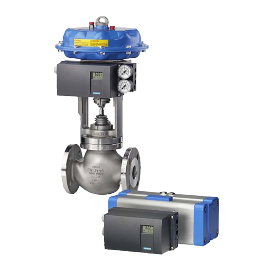
Siemens SIPART PS2 Service Manual
Smart valve positioner 4/20 ma
Hide thumbs
Also See for SIPART PS2:
- Operating instructions manual (372 pages) ,
- Compact operating instructions (294 pages) ,
- Manual (200 pages)

Related Manuals for Siemens SIPART PS2


Summary of Contents for Siemens SIPART PS2
- Page 1 Troubleshooting Guide Electropneumatic positioners SIPART PS2 4/20 mA (6DR50...6DR51...6DR52...6DR53...) Edition 08/2017...
- Page 3 ___________________ Introduction ___________________ Valve Symptom Guide ___________________ SIPART PS2 Troubleshooting Procedures ___________________ Wiring Smart Valve Positioner PS2 Troubleshooting Guide ___________________ Appendix A Service Manual 03/2017 A5E36661550-AA...
- Page 4 Note the following: WARNING Siemens products may only be used for the applications described in the catalog and in the relevant technical documentation. If products and components from other manufacturers are used, these must be recommended or approved by Siemens. Proper transport, storage, installation, assembly, commissioning, operation and maintenance are required to ensure that the products operate safely and without any problems.
-
Page 5: Table Of Contents
Table of contents Introduction ............................. 5 Purpose of this documentation ....................5 Requirements for special applications ..................5 Improper commissioning in hazardous areas ................5 Loss of explosion protection ..................... 6 Opening device in energized state ................... 6 Water in compressed air line ....................6 Loss of degree of protection ..................... - Page 6 Transmission Ratio/Slide Bar ....................49 Initialization Procedure ......................50 NOINI (P-Manual Mode) Troubleshooting ................58 SIPART PS2 Valve Positioner Fail-Safe Positions ..............62 Leaflet "Operation - a concise overview" Firmware 4.00 ............67 Leaflet "Operation - a concise overview" Firmware 5.00 ............69...
-
Page 7: Introduction
SIPART PS2 valve positioner. Many valve related issues can be discovered using the numerous SIPART PS2 features. This guide is intended to direct a qualified technician to a specific troubleshooting procedure so the root-cause failure of a valve assembly can be revealed. -
Page 8: Loss Of Explosion Protection
Introduction 1.4 Loss of explosion protection Loss of explosion protection WARNING Loss of explosion protection Danger of explosion in hazardous areas if the device is open or not properly closed. • Close the device as described in Chapter "Technical data" in Operating Instructions A5E00074631. -
Page 9: Loss Of Degree Of Protection
Introduction 1.7 Loss of degree of protection Loss of degree of protection Note Loss of degree of protection Damage to device if the enclosure is open or not properly closed. The degree of protection specified on the nameplate or in Chapter "Technical data" in Operating Instructions A5E00074631 is no longer guaranteed. -
Page 10: Customer And Product Support
Customer and Product Support Customer/Product Support For support and the location of your local Siemens representative, refer to the table below for the URL of the Process Instrumentation portion of the Siemens public Internet site. Once at the site, click Support in the right column and then Product Support. Next select the type of support desired: sales, technical (see the table below), documentation, or software. - Page 11 Introduction 1.11 Device Overview ① ⑩ Input: Supply air PZ Transmission ratio selector ② ⑪ Output: Actuating pressure Y1 Friction clutch adjustment wheel ③ ⑫ Display Basic electronics ④ ⑬ Output: Actuating pressure Y2 Connecting terminals of option modules ⑤ ⑭...
- Page 12 Introduction 1.11 Device Overview Flameproof Enclosure ● Loosen the screw below the display and flip open the cover to access the push buttons. ① ⑧ Input: Supply air PZ Restrictor Y2 ② ⑨ Output: Actuating pressure Y1 Friction clutch adjustment wheel ③...
- Page 13 Introduction 1.11 Device Overview The chart below shows the PS2's operating modes and functions Operating Mode Function Flashing "noini" No Initialization - Unit needs to be calibrated (P Manual) See Initialization Procedure (Page 50) • Initialization Mode Automatic Commissioning Parameter 4 in Configuration menu •...
- Page 14 Introduction 1.11 Device Overview Operating Representation in the Pos. Legend Mode display ① Automatic Position [%] (AUT) ② Setpoint [%] ③ Fault message ① Diagnostics Diagnostic value ② Diagnostic name ③ Diagnostic number PS2 Troubleshooting Guide Service Manual, 03/2017, A5E36661550-AA...
-
Page 15: Valve Symptom Guide
Valve Symptom Guide Possible Causes Symptoms Actuator Blow-By (double-acting only) (Page 15) • • • • • • • Actuator End-Stops (Page 15) • • Air Leak (Page 16) • • • • • • • • • Alarm Parameters (Page 17) •... -
Page 17: Troubleshooting Procedures
Troubleshooting Procedures Actuator Blow-By (double-acting only) This issue is found only with double acting applications that are utilizing both Y1 and Y2 output ports. ● One output increases air pressure while the other exhausts air pressure ● This creates the necessary differential pressure in the actuator to move the valve. ●... -
Page 18: Air Leak
Troubleshooting Procedures 3.3 Air Leak Air Leak Note For firmware 5.00.00 or greater only: Verify parameter "PNEUM" is set correctly: • "Std" = Standard Valve Block or • "FIP" = Fail In Place Valve Block ("F10" at the end of the model code indicates FIP option.) Perform a leak test. -
Page 19: Alarm Parameters
Troubleshooting Procedures 3.4 Alarm Parameters Alarm Parameters If the unit is always going in to alarm, verify configuration settings. ● Parameter "AFCT" (Default is OFF) – From AUT or MAN mode, press button for 5 seconds. Now observe the number in the lower left hand corner. -
Page 20: Booster(S) Not Properly Tuned
Troubleshooting Procedures 3.5 Booster(s) Not Properly Tuned Booster(s) Not Properly Tuned Pneumatic volume boosters should always be equipped with a bypass needle valve. This needle valve can be external or integral to the booster housing. Needle valve adjustments are necessary to achieve proper valve response. ●... - Page 21 Troubleshooting Procedures 3.5 Booster(s) Not Properly Tuned ● Once all pneumatic connections are made, and the appropriate supply pressure is applied, moving the valve assembly throughout the entire valve stroke can be accomplished using the and/or button/s. – Pressing one button delivers air slowly to the actuator. –...
-
Page 22: Change In Valve Stroke
Troubleshooting Procedures 3.6 Change in Valve Stroke Change in Valve Stroke Process Build Up Process materials can build-up on valves and valve seats. This can prevent a valve from fully closing, and cause the process to leak through the valve. Additionally process build-up can prevent the valve from fully opening. - Page 23 Troubleshooting Procedures 3.6 Change in Valve Stroke Valve Seat Wear Valve and valve seat wear can cause over-travel and process leaks. To Identify this: ● Put PS2 in Manual mode- from Auto, press button once. ● While pressing and holding button, press and hold button.
-
Page 24: Change In Tuning Parameters
3.7 Change in Tuning Parameters Change in Tuning Parameters The SIPART PS2 uses a control method called "pulse width modulation". This is a true digital control method, where piezo valves, similar to very small solenoid valves, are used to control loading and exhausting air, to and from the positioner. As such, tuning parameters listed below are based upon this control method. -
Page 25: Deadband Too Large
Troubleshooting Procedures 3.8 Deadband Too Large How to customize tuning parameters: ● Enter Diagnostic Mode: – When device is in Auto mode, press and hold all three buttons down at the same time: – Diagnostic name is shown in lower right of display. ●... -
Page 26: Deadband Too Small
Troubleshooting Procedures 3.9 Deadband Too Small ● If deadband value is too large for the application, the PS2 is compensating to prevent valve oscillations. These valve oscillations could be: – Too much stiction; see Stiction (Page 36). – Too many step changes from process controller. This is a process control loop issue. Discuss issue with operator and/or plant process engineer. -
Page 27: Erratic Feedback
Troubleshooting Procedures 3.10 Erratic Feedback There are two settings for the PS2 deadband: "Auto" or a fixed numerical value. ● When configuration parameter "DEBA" = "Auto", the deadband value is dynamic and changes per the process conditions. In other words, the deadband value changes if stiction or oscillation is detected. -
Page 28: Erratic Input Signal
● If false feedback signal is corrected by moving the valve, consider Non-Contacting technology. Contact Siemens technical support for assistance: 1-800-333-7421. ● If false feedback is still present when moving the valve, verify: ● Slide bar is in proper location: First, unlock slide bar: see Transmission Ratio/Slide (Page 49). -
Page 29: High Vibration
● Recommended continuous duty range of the complete fitting – <= 30 m/s² (98.4 ft/s²) without resonance sharpness ● If excessive vibration cannot be avoided, consider Non-Contacting technology. Contact Siemens technical support for assistance: 1-800-333-7421. 3.13 Initialization Incomplete Fault Profile (symptoms) -
Page 30: Insufficient Supply Air
Troubleshooting Procedures 3.14 Insufficient Supply Air Fault Profile (symptoms) Possible Cause(s) Corrective Measures Positioner remains in Actuator travel time is too high. Open the restrictor com- • • "RUN 3" pletely and/or set the supply Air Leak (Page 16) • air to the highest permissible Non-active zone is in the valve •... -
Page 31: Loose Or Worn Linkage
Troubleshooting Procedures 3.15 Loose or Worn Linkage 3.15 Loose or Worn Linkage CAUTION Pinch Hazard Use caution when inspecting linkage during operation. A valve positioner’s performance is directly dependent upon its mechanical connection to the actuator. For example, if the mechanical coupling is loose or worn on the positioner’s input shaft, valve performance will suffer. - Page 32 Troubleshooting Procedures 3.15 Loose or Worn Linkage ● Flameproof enclosures on rotary actuators require the black-wheel coupler design, not the SST coupler. Figure 3-1 FlameProof coupler and SST coupler ● Unscrew cap from PS2 enclosure. ● Locate the internal input shaft, see image below. ●...
-
Page 33: Manual Mode
Troubleshooting Procedures 3.16 Manual Mode 3.16 Manual Mode When bottom section of display shows: "MANxx" (xx = input signal), the unit is in Manual mode. In Manual mode, the unit ignores setpoint command signal. It is possible to use the and/or buttons to manually drive the actuator. - Page 34 Troubleshooting Procedures 3.18 Parameter 1.YFCT Use Inverted, indicated with the minus symbol if valve moves in opposite direction as described above. ● turn/-turn: For a part-turn actuator with a directly mounted positioner. ● WAY/-WAY: For a linear actuator with a carrier pin mounted on the lever. ●...
-
Page 35: Parameter 6.Scur
Troubleshooting Procedures 3.19 Parameter 6.SCUR Figure 3-3 Linear Application Linear Applications, see Initialization Procedure (Page 50) 3.19 Parameter 6.SCUR Default setting is: "4 mA". ● From AUT or MAN mode, press button for 5 seconds. Now observe the parameter name in the lower right corner. ●... -
Page 36: Reversing The Action
Troubleshooting Procedures 3.21 Reversing the Action 3.21 Reversing the Action There are two ways to invert the action and display, one requires re-initialization. No re-initialization procedure This procedure inverts the physical action and display of the positioner. ● Parameter "SDIR" reverses the physical action –... -
Page 37: Setpoint Ramping
PS2 board. ● Resolve power issue and replace PS2 circuit board. Board part numbers can be found in PS2 Operating Instructions P/N#: A5E00074631, or contact Siemens. PS2 Troubleshooting Guide... -
Page 38: Stiction
Troubleshooting Procedures 3.24 Stiction If milliamp changes with input signal, check PS2 configuration. ● To restore all PS2 parameters to factory setting: – From Auto/Manual mode, press and hold button until display changes. – Press and release button and go to "PRST" parameter. –... -
Page 39: Too Much Restriction
Troubleshooting Procedures 3.26 Too Much Restriction High supply pressure can cause quick valve responses, and lead to overshoots, oscillations, and incomplete initialization. If high supply pressure is required for application, the minimum travel time may not be met. The PS2 requires at least 1.0 second of travel time for each valve direction. -
Page 40: Tubing Lines Configuration
It is recommended to install a regulator on the supply line, upstream from the positioner, and to regulate supply pressure so it does not exceed the maximum pressure rating of the PS2 and the actuator. Siemens offers a filter regulator, Model 91H, which regulates pressure and removes debris. - Page 41 Troubleshooting Procedures 3.29 Valve Block Failure Activate NOINI Mode (if not already activated) ● Enter configuration mode and go to parameter: "4.INITA". – From AUT or MAN mode, press button for 5 seconds. – Parameter number will be displayed in lower left hand corner. –...
- Page 42 Troubleshooting Procedures 3.29 Valve Block Failure If PS2 can output full supply pressure and fully exhaust, then something else is preventing actuator from fully closing or opening. Check valve assembly for mechanical blockage and air leaks. Also verify supply is at required pressure for application. ●...
- Page 43 Troubleshooting Procedures 3.29 Valve Block Failure ● Install appropriate thread type pipe plug into each output port(s).The only pneumatic line connected to the PS2 should be supply. See photo below. Note Single-acting only has one output. ● Use two-button method to pressurize the output chamber. –...
-
Page 44: Valve Does Not Go Fully Closed/Open
Troubleshooting Procedures 3.30 Valve Does Not Go Fully Closed/Open 3.30 Valve Does Not Go Fully Closed/Open ● From AUT or MAN mode, press button for 5 seconds. – Observer parameter name in the lower left hand corner. ● Continue to press button until "YCLS"... -
Page 45: Wiring
Wiring 2-Wire Connection, with terminals 6 through 10 ① ③ Non-hazardous area Binary input 1 ② ④ Hazardous area Signal source ③ ⑤ Basic electronics HART communicator ✓ Requires a regulated current source NOT a voltage source ✓ Unit requires at least 3.6 milliamps to power on ✓... -
Page 46: 2-Wire Connection, Terminals 2 Through 10
Wiring 4.2 2-Wire Connection, terminals 2 through 10 2-Wire Connection, terminals 2 through 10 ① ④ Non-hazardous area Binary input 1 ② ⑤ Hazardous area Signal source ③ ⑥ Basic electronics HART communicator ✓ Requires a regulated current source NOT a voltage source ✓... - Page 47 Wiring 4.3 Power Specifications Basic device Basic device Basic device Basic device with explosion protec- without Ex protec- with Ex d explo- with "ia" explosion tion "ic", "na", "t" tion sion protection protection Without Hart • (6DR50..) 6.36 V (=318 Ω) 6.36 V (=318 Ω) 7.8 V (=390 Ω) 7.8 V (=390 Ω)
-
Page 48: To 20 Ma Feedback Module (Iy Module)
Wiring 4.4 4 to 20 mA Feedback Module (Iy Module) 4 to 20 mA Feedback Module (Iy Module) ① ③ Non-hazardous area Position feedback module ② ④ Hazardous area Feed splitter ✓ Typically requires a 24 V DC source ✓ For hazardous areas, consult following Feedback Module Power Specifications Chart and local safety guidelines ✓... - Page 49 Wiring 4.4 4 to 20 mA Feedback Module (Iy Module) Basic device Basic device Basic device Basic device with explosion protection without Ex protection with Ex d explosion with "ia" explosion "ic", "nA", "t" protection protection = 30 V "ic": For connecting to •...
-
Page 51: Transmission Ratio/Slide Bar
Appendix A Transmission Ratio/Slide Bar There are two mechanical adjustments for 33 ̊ and 90 ̊ degrees on the positioner. The important information to remember is the order of which the adjustments are completed. ① ③ ● Verify the Gear Latch is in the neutral positon which is shown with number ●... -
Page 52: Initialization Procedure
"Operating Instructions" manual supplied on the CD in the positioner’s box. Under the Navigation tab, expand "electropneumatic positioners" and then "SIPART PS2". Choose input source, i.e. 4-20 mA = "SIPART PS2 with and without HART. PS2 Troubleshooting Guide... - Page 53 Appendix A A.2 Initialization Procedure Positioner Calibration Remove the cover, The PS2 has an LCD display and three (3) input buttons; 1. When the positioner is powered up for the first time, the display will flash NOINI (no initialization) on the bottom right of the screen. 2.
- Page 54 Appendix A A.2 Initialization Procedure ① ③ 3. Verify the Gear Latch is in the neutral positon which is shown by the number in the following illustration. PS2 Troubleshooting Guide Service Manual, 03/2017, A5E36661550-AA...
- Page 55 Appendix A A.2 Initialization Procedure 4. Set Transmission Ratio Selector (Slide Bar) according to the actuator’s requirements: – Rotary - Always 90° (Step 4A) – Linear less than 25 mm/1 inch = 33° (Step 4B) – Linear greater than or equal to 25 mm/1 inch = 90° (Step 4B) Proceed to adjust the gear latch to match the Transmission Ratio/Slide Bar.
- Page 56 Appendix A A.2 Initialization Procedure 6. Using the buttons, scroll to appropriate actuator type. See description below. – turn/-turn: Use this setting for a part-turn actuator with a directly mounted positioner. – WAY/-WAY: Use this setting for a linear actuator with a carrier pin mounted on the lever.
- Page 57 Appendix A A.2 Initialization Procedure 10.If the actuator strokes and stops, and the display reads; the red colour in this description is for recognition only); The down tolerance has been exceeded. (A) Confirm the transmission bar is properly set for actuator stoke. See step 4. (B) Adjust the Friction Clutch so the P number is 6.4 or as close as possible.
- Page 58 Check Leaflet provided inside the housing for parameter number. ● Foundation Fieldbus requires a special process for configuring the function blocks in order to control the valve. For help with the communication step, contact Siemens Technical Support. How to reverse the action: If it is found that the valve action is backwards for the application, there are two ways to address this but one requires re-initialization.
- Page 59 Note If using the alarm card, tight closing, or advance diagnostics, the values may not match Option One actual valve position. Recommend for reversing action when possible. See also Instructions and manuals (http://www.siemens.com/processinstrumentation/documentation) PS2 Troubleshooting Guide Service Manual, 03/2017, A5E36661550-AA...
-
Page 60: Noini (P-Manual Mode) Troubleshooting
Appendix A A.3 NOINI (P-Manual Mode) Troubleshooting NOINI (P-Manual Mode) Troubleshooting This document can be considered as a ‘catch-all’ procedure that can uncover all issues that will prevent successful PS2 initialization. For mechanical installation of positioner to actuator, refer to the specific mounting kit instructions. Note This procedure will move the valve throughout the entire valve stroke. - Page 61 Appendix A A.3 NOINI (P-Manual Mode) Troubleshooting ● If there is no change with the large number on the display: – Verify feedback connection is installed on positioner’s input shaft; see photos below for rotary and linear coupling examples. – Verify potentiometer’s ribbon cable is plugged into MPU board. ○...
- Page 62 Appendix A A.3 NOINI (P-Manual Mode) Troubleshooting ● The large number should be repeatable at each end-stop. – To check for loose linkage, move valve to fully closed position. ○ Take note of the numerical value on display. ● Move valve to fully open position. –...
- Page 63 Appendix A A.3 NOINI (P-Manual Mode) Troubleshooting Note Do not use the large number on the display to determine mid-travel position, use the mechanical indicator on the actuator. ● Once at the mid-travel position, release push-buttons. ● Adjust slip clutch, until number in display is within a range of: 48-52. Figure A-1 Slip Clutch ●...
-
Page 64: Sipart Ps2 Valve Positioner Fail-Safe Positions
Appendix A A.4 SIPART PS2 Valve Positioner Fail-Safe Positions ● Adjust slip clutch until number in display is within a range of: 48-52. Figure A-2 Slip Clutch ● Move valve so the numerical number decreases, either by pressing the button. - Page 65 Appendix A A.4 SIPART PS2 Valve Positioner Fail-Safe Positions SIPART PS2 Attributes ● Separate models for single and double-acting applications. ● Single-acting units vent output pressure upon loss of control signal and supply air. ● Double-acting units: Y1 goes to maximum pressure & Y2 vents upon loss of control signal.
- Page 66 Appendix A A.4 SIPART PS2 Valve Positioner Fail-Safe Positions Figure A-3 Figure A-3 Reaction to failure of auxiliary powers PS2 Troubleshooting Guide Service Manual, 03/2017, A5E36661550-AA...
- Page 67 Figure A-4 Figure A-4 Reaction to failure of auxiliary power with fail in place Profibus Parameters The following safety parameters are accessible using the local pushbuttons or Siemens’ SIMATIC PDM software. FSTY, Fail Safe Type: Determines position of actuator upon loss of digital communication.
- Page 68 Appendix A A.4 SIPART PS2 Valve Positioner Fail-Safe Positions FSAC, Fail Safe factory: As per power failure modes indicated in above table: ● Single-acting models - Y1 exhaust to zero pressure. ● Double-acting models- Y2 exhaust to zero and Y1 increases to supply pressure.
-
Page 69: Leaflet "Operation - A Concise Overview" Firmware 4.00
Appendix A A.5 Leaflet "Operation - a concise overview" Firmware 4.00 Leaflet "Operation - a concise overview" Firmware 4.00 PS2 Troubleshooting Guide Service Manual, 03/2017, A5E36661550-AA... - Page 70 Appendix A A.5 Leaflet "Operation - a concise overview" Firmware 4.00 PS2 Troubleshooting Guide Service Manual, 03/2017, A5E36661550-AA...
-
Page 71: Leaflet "Operation - A Concise Overview" Firmware 5.00
Appendix A A.6 Leaflet "Operation - a concise overview" Firmware 5.00 Leaflet "Operation - a concise overview" Firmware 5.00 PS2 Troubleshooting Guide Service Manual, 03/2017, A5E36661550-AA... - Page 72 Appendix A A.6 Leaflet "Operation - a concise overview" Firmware 5.00 PS2 Troubleshooting Guide Service Manual, 03/2017, A5E36661550-AA...
- Page 73 Siemens Industry, Inc., Industry Automation Process Instrumentation 1201 Sumneytown Pike Subject to change without prior notice Spring House, PA A5E36661550 Rev. AA United States 19477-0900 © Siemens AG 2017 www.siemens.com/automation/support-request...