Siemens SIPART PS2 Installation Instruction
Mounting bracket kit
Hide thumbs
Also See for SIPART PS2:
- Operating instructions manual (372 pages) ,
- Compact operating instructions (294 pages) ,
- Manual (200 pages)
Advertisement
Quick Links
Siemens Industry, Inc.
BRACKET KIT PN TGX:16152-695
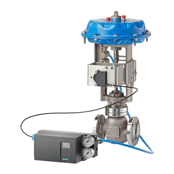
This publication provides installation instructions to mount a Siemens SIPART PS2 valve positioner
onto an Armstrong Python series actuator, model 1100, and to install the mechanical feedback
linkage. A typical installation is shown in Figure 1.
Bracket kit parts are shown on Page 2. Page 3 has a table that lists actuator nameplate data and
related installation selections. Installation procedures begin on page 3. Initial PS2 setup is found on
page 8. Customer/product support information located on page 11.
KIT INSTALLATION INSTRUCTION
SIPART PS2 Mounting Bracket Kit for
Armstrong Python 1100 Series Actuator
FIGURE 1 Mounting Kit Installation, Exploded View
A5E37606851A
Rev 1
April, 2016
Advertisement

Related Manuals for Siemens SIPART PS2


Summary of Contents for Siemens SIPART PS2
- Page 1 SIPART PS2 Mounting Bracket Kit for Armstrong Python 1100 Series Actuator This publication provides installation instructions to mount a Siemens SIPART PS2 valve positioner onto an Armstrong Python series actuator, model 1100, and to install the mechanical feedback linkage. A typical installation is shown in Figure 1.
- Page 2 15900-795 PARTS, BRACKET KIT TGX:16152-695 Description Part Illustration, Not Shown to Scale Qty/Kit Mounting Plate 2.03 Feedback Pin 2.28 Feedback Pin 2.61 Feedback Pin 5/16”-18 X 0.75 Long Hex Head Screw 5/16 Med Split washer 3/8-16 Hex Nut M6 x 12 Hex Head Screws M6 Lock washers Kit Installation Instruction, this publication, PN A5E37606851A...
-
Page 3: Installation
The current revision of the positioner instruction is available for download at the Siemens Internet site. See Customer/Product Support later in this Instruction for the URL. Before beginning the installation, note the following cautions. Do not apply supply pressure to the actuator or the valve CAUTION positioner during the installation process. - Page 4 15900-795 Assemble Retaining Clip to Feedback Lever 1. On the actuator nameplate, read the actuator model and valve travel for the actuator at hand. Find that model and travel in Table 2 below. The retaining clip position is shown to the right of the valve travel.
- Page 5 15900-795 Install the Linear Adapter on the Positioner Input Shaft 1. Using the supplied hex wrench, screw the setscrew into the linear adapter until the tip of the setscrew is just visible in the hole in the end of the adapter. See the drawing below, left. Set Screw Linear Adapter Input Shaft...
- Page 6 15900-795 Install Mounting Plate and PS2 Assembly onto Actuator 1. Install 5/16” lock washers onto 5/16-18x0.75 Hex head bolts 2. Since mounting plate is intended for several actuator models, be sure fasteners are inserted through proper slots and/or holes. Proper slots/holes are shaded in table 3 below. Proper Bracket Proper Bracket Actuator...
- Page 7 15900-795 Table 4, Mounting Hole Locations (PS2 not shown for clarity) 4. While securing mounting plate assembly to actuator, adjustments to feedback pin depth may be necessary so pin protrudes through the feedback arm a minimum 0.10” (2.5mm) to 0.15 (3.8mm) max.
- Page 8 15900-795 INITIAL PS2 SETUP Perform the following steps to set the transmission gear ratio switch, apply instrument air and electrical power, and manipulate the three TABLE 5, PS2 Transmission setup pushbuttons to initially set up the PS2. Read the cautions on Gear Ratio Switch Setting page 3 before proceeding.
- Page 9 15900-795 7. If "NOINI" is flashing on display, skip to step 12, otherwise go to step 8. FIGURE 6 PS2 Configuration Mode Display (sample) 8. Press and hold [HAND] button to enter configuration mode. When display changes, release button. See Figure 6. Hand (Minus) + (Plus)
- Page 10 “YCUP” – Input signal threshold value for tight closing, top position “PRST” – Parameter reset: Return all parameter to factory default values 29. If needed, refer to the SIPART PS2 manual (see the footnote on page 2) for complete installation, configuration, and service information.
- Page 11 Siemens Industry, Inc. assumes no liability for errors or omissions in this document or for the application and use of information in this document. The information herein is subject to change without notice.