Table of Contents
Advertisement
Quick Links
Download this manual
See also:
User Manual
Advertisement
Table of Contents

Related Manuals for Lexmark Pro5500t


Summary of Contents for Lexmark Pro5500t
- Page 1 ™ Lexmark Pro5500t, Pro5500 4447-20x • Table of contents • Start diagnostics • Safety and notices • Trademarks • Index Lexmark and Lexmark with diamond design are trademarks of Lexmark International, Inc., registered in the United States and/or other countries.
- Page 2 Lexmark, Lexmark with diamond design, and MarkNet are trademarks of Lexmark International, Inc., registered in the United States and/or other countries. PCL® is a registered trademark of the Hewlett-Packard Company.
-
Page 3: Table Of Contents
4447-20x Table of contents Previous Table of contents ............iii Safety information. - Page 4 4447-20x Blank page ..............2-8 Previous Blurred or fuzzy print out .
- Page 5 4447-20x Paper exit tray full ............. . 2-80 Previous Paper out/paper low service check .
- Page 6 4447-20x Print Purge Page ............. . . 3-14 Previous De-Prime PH .
- Page 7 4447-20x ADF input tray removal ............4-21 Previous ADF door removal .
-
Page 8: Safety Information
4447-20x Previous Safety information • The safety of this product is based on testing and approvals of the original design and specific components. The manufacturer is not responsible for safety in the event of use of unauthorized replacement parts. Next •... - Page 9 4447-20x Previous Sicherheitshinweise • Die Sicherheit dieses Produkts basiert auf Tests und Zulassungen des ursprünglichen Modells und bestimmter Bauteile. Bei Verwendung nicht genehmigter Ersatzteile wird vom Hersteller keine Verantwortung oder Haftung für die Sicherheit übernommen. Next • Die Wartungsinformationen für dieses Produkt sind ausschließlich für die Verwendung durch einen Wartungsfachmann bestimmt.
- Page 10 4447-20x Previous Informació de Seguretat • La seguretat d'aquest producte es basa en l'avaluació i aprovació del disseny original i els components específics. El fabricant no es fa responsable de les qüestions de Next seguretat si s'utilitzen peces de recanvi no autoritzades. •...
- Page 11 4447-20x Previous Next Go Back 。 , 。 、 。 。 Safety information...
-
Page 12: Preface
4447-20x Preface Previous This manual contains maintenance procedures for service personnel. It is divided into the following chapters: General information contains a general description of the printer and the maintenance approach used to Next repair it. Special tools and test equipment, as well as general environmental and safety instructions, are discussed. -
Page 13: Change History
4447-20x Previous Change history Revision date Updates 2012/07/05 • Updated the following error codes in the “Error code table” on page 2-38: Next - 181.10x to 181.257, 181.258, 181.259 - 181.201 to 181.513 - 181.300 to 181.768 Go Back - 181.301 to 181.769 - 181.302 to 181.770 - 181.303 to 181.771 - 181.40x to 181.1025, 181.1026, 181.1027, 181.1028, 181.1029, 181.1030... -
Page 14: Go Back
4447-20x Previous Navigation buttons This manual contains navigation buttons in the right margin of each page, making it easier and quicker to navigate. Next Button Description Previous Click to move the document view backward by one page. Go Back Next Click to move the document view forward by one page. -
Page 15: General Information
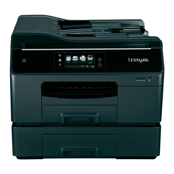
1. General information Previous The Lexmark™ Pro5500t and Pro5500 (4447-20x) Series are small to medium business class inkjet-based all-in-one (AIO) machines that combine print, scan, copy, fax, and photo functions in both monochrome and color. The machines can either be used in standalone mode or through a host PC. -
Page 16: Options And Features
4447-20x Previous Options and features Available options for the Pro5500 Series are the following: • 300-sheet input tray Next • 550-sheet input tray Feature / Function Capability Go Back Display 4.3” color, non-rotating touchscreen with LED backlight Memory • Non-volatile storage partition: 4MB •... -
Page 17: Ieee 1284 String
PRINTER Description (DES): Lexmark Pro5500 Series Comment: ECP 1.0 LV_043D (Lexmark vendor ID) LP_01D7 (Product ID value stored in NV) LF_006B (Lexmark NPA Family ID) Operating Modes Mode Description Normal Factory default Eco-mode (Off is default): Save energy and paper by activating Eco-Mode. It automatically dims the printer display light, puts the printer into Sleep mode after a specified period of inactivity. -
Page 18: Dimensions
4447-20x Dimensions Previous Below are the dimensions of the printers without the second tray, and with the output tray closed: Model Width Depth Height Weight Next Pro5500 Series with the following conditions: 500 mm 417 mm 300 mm 15.57kg • Closed with exit tray retracted •... -
Page 19: Power And Electrical Specifications
The power consumption levels listed in the previous table represent time-averaged measurements. Instantaneous power draws may be substantially higher than the average. Values are subject to change. Visit www.lexmark.com for current values. Sleep Mode This product is designed with an energy-saving mode called the Sleep Mode. The Sleep Mode saves energy by lowering power consumption during extended periods of inactivity. -
Page 20: Acoustics
4447-20x Acoustics Previous All acoustic measurements are made in accordance with ISO 7779 and reported in conformance with ISO9296. Operating mode Next 1-meter average sound pressure, dBA Printing (Normal mode, 600 dpi) <= 45 dBA Scanning from flatbed (300 dpi) <= 28 dBA Go Back Scanning from ADF (300 dpi) -
Page 21: Print Specifications
4447-20x Previous Print specifications Print function Capability Print modes / resolution Host-based: Next • Draft mode: 600 x 1,800 dpi • Normal mode: 1,200 x 1,800 dpi • Plain paper best: 1,200 x 1,800 dpi Go Back • Glossy photo draft: 2,400 x 1,800 dpi •... - Page 22 4447-20x Previous Print function Capability Memory cards and file types View and select photos on memory card as thumbnails Supported memory cards: • Secure Digital (SD) • Secure Digital High Capacity (SDHC) Next • Micro Secure Digital (with adapter) (Micro SD) •...
-
Page 23: Scan Specifications
4447-20x Previous Scan specifications Scanner function Capability Next Scanner type • Flatbed—CIS 3-channel • ADF—CIS 3-channel • DC drive systems (flatbed and ADF) • Bulb type: LED Go Back Scan method Single pass duplex scan Note: Duplex scan is applicable to Pr05500 model only. Optical resolution (Scan direction) 300/600/1,200 dpi Note: 1,200 dpi is supported on the flatbed only. -
Page 24: Scanner Resolutions Per Mode
4447-20x Previous Scanner function Capability Scan features • Scan to: E-mail with attachment (.pdf and .jpeg file types) • Scan to: Host (local and network TWAIN, local WIA) • Scan to: Scan Profile Next Scan to: Temporary profile (Java Applet) Scan to: Permanent profile •... - Page 25 4447-20x Previous Scanning mode Output resolution Optical resolution Fax standard (mono) 200 x 100 Flatbed: 600 scan, 200 feed ADF: Next 600 scan, 300 feed Fax fine 200 x 200 Flatbed: Go Back 600 scan, 400 feed (color) 600 scan, 200 feed (mono) Flatbed: 600 scan, 200 feed (color) 600 scan, 400 feed (mono)
- Page 26 4447-20x Previous Scanning mode Output resolution Optical resolution Scan-to-host 100 dpi 100 x 100 Flatbed: 300 scan, 200 feed (color) 600 scan, 200 feed (mono) Next ADF: 300 scan, 200 feed (color) 600 scan, 300 feed (mono) Go Back Scan-to-host 150 dpi 150 x 150 Flatbed: 300 scan, 200 feed (color)
-
Page 27: Copy Specifications
4447-20x Previous Copy specifications Copy function Capability Copy type Standalone BW and color copy Next Copy modes One-touch select from the operator panel (defaults to color copy mode) Resolution/Quality Host-based: Go Back Color copy: • Best quality, color photocopy, photo/glossy paper: 300 x 300 ppi scan 7,200 x 1,800 dpi print •... - Page 28 • Heavy plain • Letterhead • Premium plain • ColorLok Certified Plain • Glossy photo paper • Lexmark photo • Lexmark PerfectFinish photo • Business card • Matte photo paper • Inkjet Matte Brochure • Inkjet Glossy Brochure Host-based (selected via driver): Supported media types: •...
- Page 29 4447-20x Previous Copy function Capability Media sizes (standalone) Non-borderless sizes: • Letter (8.5 x 11 in.) • Legal (8.5 x 14 in.) • JIS B5 Next • A4 (210 x 297 mm) • Executive • A5 Go Back • universal •...
- Page 30 4447-20x Previous Copy function Capability Copy features Standalone: • One-touch copy • Reduction/enlargement: Custom (25% to 400%, in 1% increments) • Reduction/enlargement: Preset Next - 100% - Fit to Page - Borderless Go Back • Copy to selected paper sizes •...
-
Page 31: Fax Specifications
4447-20x Previous Fax specifications Fax function Capability Fax type Standalone BW and color faxing Next Paper size output Send/receive color • Legal • letter (default for US) Go Back • A4 (default for Europe) Modem speed and class • Speed-- 33.6 Kbps •... - Page 32 4447-20x Previous Fax function Capability Fax features • 160- page memory (at standard resolution) • 4 MB fax memory • 64 digit fax number support • 89 speed dials, 10 group dials with 30 numbers per group Next • Auto answering •...
-
Page 33: Media Handling
4447-20x Previous Media handling Input and output sources Next Sheet numbers are assuming Pro5500t Pro5500 20 lb. xerographic paper Standard input tray 300-sheet 300-sheet Go Back Optional input tray 300/550-sheet Duplex type Integrated print duplex Integrated print duplex ADF scanner type... -
Page 34: Media Input Type Specifications
Labels ✓ ✓ ✘ Envelope ✓ ✓ ✓ Heavy plain ✓ ✓ ✓ Business card ✓ ✓ ✘ Lexmark PerfectFinish photo ✓ ✓ ✘ Lexmark photo ✓ ✓ ✘ Glossy photo ✓ ✓ ✓ Matte photo ✓ ✓ ✓ Inkjet matte brochure light ✓... -
Page 35: Input Feed Characteristics
4447-20x Previous ✓ -- Supported without size sensing ✘ -- Not supported Next ✓ ✘ ✘ ✓ ✓ ✘ ✓ 4 x 8 in. Go Back ✓ ✘ ✘ ✓ ✓ ✘ ✓ 5 x 7 in. ✘ ✘ ✘ ✘... - Page 36 4447-20x Previous Physical page feed Media Size Feed orientation direction Letter Portrait Short-edge Next Legal Portrait Short-edge Portrait Short-edge Go Back Portrait Short-edge Portrait Short-edge Portrait Short-edge 3 x 5 in Portrait Short-edge 4 x 6 in Portrait Short-edge 4 x 8 in Portrait Short-edge 5 x 7 in...
-
Page 37: Portrait Feed Orientation
4447-20x Portrait feed orientation Previous Portrait Feed Orientation Next Go Back Page outline for largest possible page outline for paper/envelope Reference Edge (Start of Scan Line) Reference Edge (First Writing Line) FEED DIRECTION 1-23 General information... -
Page 38: Landscape Feed Orientation
4447-20x Landscape feed orientation Previous Landscape Feed Orientation Next Go Back Page outline for largest possible page outline for paper/envelope Reference Edge (Start of Scan Line) Reference Edge (First Writing Line) FEED DIRECTION 1-24 General information... -
Page 39: Reverse Portrait Feed Orientation
4447-20x Reverse portrait feed orientation Previous Reverse Portrait Feed Orientation Next Go Back Page outline for largest possible page outline for paper/envelope Reference Edge (Start of Scan Line) Reference Edge (First Writing Line) FEED DIRECTION 1-25 General information... -
Page 40: Reverse Landscape Feed Orientation
4447-20x Reverse landscape feed orientation Previous Reverse Landscape Feed Orientation Next Page outline for Go Back largest possible page outline for paper/envelope Landscape Reference Edge (Start of Scan Line) Reference Edge (First Writing Line) FEED DIRECTION Media output size and type specifications There is a standard 150-sheet bin available for this printer and no additional output options. -
Page 41: Media Guidelines
4447-20x Media guidelines Previous Note: The ADF assembly only supports plain paper (18 to 24 lb) only. Paper characteristics Next The following paper characteristics affect print quality and reliability. Consider these characteristics when evaluating new paper stock. Go Back • Weight—The printer can automatically feed paper weights from 60 to 176 g/m2 (16 to 47 lb bond) grain long. -
Page 42: Selecting Preprinted Forms And Letterhead
As an environmentally conscious company, Lexmark supports the use of recycled office paper. In 1998, Lexmark presented to the US government a study demonstrating that recycled paper produced by major mills in the US fed as well as non-recycled paper. However, no blanket statement can be made that all recycled paper will feed well. -
Page 43: Tools Required For Service
4447-20x Previous Tools required for service Flat-blade screwdrivers #1 Phillips screwdriver #2 Phillips screwdriver Next #10 Torxs screwdriver Spring hook Analog or digital multimeter Go Back Acronyms End-of-form Electrostatic Discharge Flat Flexible Cable Field Replaceable Unit Gigabyte Ink-sense Pinch Valve Light-Emitting Diode Maintenance Pinch Valve NVRAM... -
Page 44: Diagnostic Information
4447-20x 2. Diagnostic information Previous Start Next CAUTION Unplug power cord from the electrical outlet before you connect or disconnect any cable or Go Back electronic board or assembly for personal safety and to prevent damage to the printer. Disconnect any connections between the printer and PCs/peripherals. The diagnostic information in this chapter leads you to the failing part. -
Page 45: Power-On Self Test (Post) Sequence
Go Back Energy Star appears on the screen for approximately five seconds. Lexmark and a progress bar indicating the remaining time for POST appear on the screen. The icons beside the display light up for approximately one second. The engine initializes. -
Page 46: Print Quality Issues
Technical Support Center: Make sure the ink cartridges are properly installed, and are genuine Lexmark cartridges. Turn off the printer by unplugging the power cord. Wait for 10 seconds, and turn on the printer. Resend the print job. Send another type of print job. Check the ink level of the cartridges, and replace them if necessary. - Page 47 Missing nozzles Technical Support Center: Make sure the ink cartridges are properly installed, and are genuine Lexmark cartridges. Check the ink level of the cartridges, and replace them if necessary. From the home screen, touch > More Options > Deep Clean Printhead >...
- Page 48 Check the paper setting, and make sure that it is set to the correct paper Next size and paper type. Check the paper if it is within Lexmark media specifications. See “Media handling” on page 1-19.
-
Page 49: Black Print Out From A Print Job
Marketing Name Black print out from a print job Previous Before starting, check the media route for foreign objects, such as staples, clips, and scraps, in the media path. Step Check Next Turn off the printer by unplugging the power cord. Go to step 2. - Page 50 4447-20x Previous Step Check Check the J1, J2, and J3 connectors on the carrier Go to step 8. Do any of the card for proper connection and damage. following: Next Reseat the J1, J2, and J3 cables. • If the cables are damaged, then Are the cables and connectors free from damage? go to step 11.
-
Page 51: Blank Page
Marketing Name Blank page Previous Blank pages may be caused by improperly installed ink cartridges. Make sure the ink cartridges are properly installed.Reinstall the ink cartridges. The cartridges should click firmly into their matching color slots. Next Step Questions / actions Deep clean or clean the printhead. -
Page 52: Blurred Or Fuzzy Print Out
4447-20x Previous Step Questions / actions Replace the tank receiver assembly. See “Tank Go to step 9. Problem resolved receiver assembly with inlet removal” on page 4-79. Does the problem remain? Next Replace the system board. See “System board Go to step 10. Problem resolved removal”... - Page 53 Marketing Name Previous Step Questions / actions Check the condition of the carrier assembly. Manually Go to step 6. Go to step 9. move the carrier assembly from left to right to see if it can move easily. Check if the carrier shaft is still in good condition and does not need regreasing.
-
Page 54: Missing Color Or Color Starvation Service Check
4447-20x Missing color or color starvation service check Previous Step Questions / actions Next Check the ink tubes going to the printhead if they Go to step 2. Go to step 4. are filled with ink and that no air is inside the tubes. Is ink present in all the ink tubes? Go Back Deep clean or clean the printhead. - Page 55 Marketing Name Previous Step Questions / actions Check the J1, J2, and J3 connectors on the carrier Go to step 7. Do any of the card for proper connection and damage. following: Next Reseat the J1, J2, and J3 cables. •...
-
Page 56: Print Quality Check
4447-20x Print quality check Previous Step Questions / actions Turn off the printer by unplugging the power cord. Wait Go to step 2. Problem for 10 seconds, and turn on the printer. Run the print job resolved Next again. Does the problem remain? Go Back Run a test print. - Page 57 Marketing Name Previous Step Questions / actions Check the J18, J19, and J20 cables and connectors on Go to step 9. Do any of the the system board for proper connection to the carrier following: card. Also check them for damage. •...
-
Page 58: Print Skew
4447-20x Previous Step Questions / actions Replace the tank receiver assembly. See “Tank Go to step 14. Problem receiver assembly with inlet removal” on page 4-79. resolved Does the problem remain? Next Replace the inlet with tube. See “Tank receiver Go to step 15. - Page 59 Marketing Name Previous Step Questions / actions Check the feed assist rollers and duplex rollers for Do any of the Go to step 8. contamination, wear, and damage. following: Are the rollers worn, contaminated, and damaged? • If the duplex rollers are Next damaged,...
-
Page 60: White Lines/Missing Nozzles
4447-20x Previous Step Questions / actions Replace the duplex unit. See “Duplex unit removal” Go to step 15. Problem on page 4-11. resolved Does the problem remain? Next Replace the input tray. See “Input tray removal” on Go to step 16. Problem page 4-8. - Page 61 Marketing Name Previous Step Questions / actions Deep clean or clean the printhead. From the home Go to step 3. Problem resolved screen, touch > More Options > Deep Clean Next Printhead > Deep Clean Color and Black Run a test print. From the home screen, touch >...
-
Page 62: Adf & Scanner Image Issues
4447-20x Previous Step Questions / actions Check the printhead cable connector for proper Go to step 10. Reseat the cable. connection to the carrier card. Next Is the printhead cable properly connected to the carrier card? Replace the printhead. See “Printhead removal”... - Page 63 Marketing Name Previous Symptom Action Copy skew Technical Support Center: From the ADF: Try one or more of the following: Next • Make sure that the paper is inserted correctly on the ADF input tray. Set the paper guides according to the paper size. •...
- Page 64 Clear any obstruction on the ADF and exit Go Back tray paper paths. • Check the paper if it is within Lexmark media specifications. “Media handling” on page 1-19. If the problem remains, then replace the printer.
-
Page 65: Black Print Out From A Simplex Scan/Copy Job
Marketing Name Black print out from a simplex scan/copy job Previous Before starting, check the media route for foreign objects, such as staples, clips, and scraps, in the media path. Step Check Next Turn off the printer by unplugging the power cord. Go to step 2. -
Page 66: Black Print Out From A Duplex Scan/Copy Job
4447-20x Previous Step Check Check the J28 connector for proper connection and Go to step 11. Go to step 13. damage. Reseat the cable. Next Is the J28 cable free from damage? Check the J47 connector for proper connection and Go to step 12. - Page 67 Marketing Name Previous Step Check Isolate which scan bar is damaged. Run a Go to “Black Go to step 6. scan/copy job from the flatbed scanner. print out from a simplex Next Is there a problem with the print quality? scan/copy job”...
-
Page 68: Copy Skew
4447-20x Copy skew Previous Step Questions / actions Turn off the printer by unplugging the power cord. Wait Go to step 2. Problem for 10 seconds, and turn on the printer. Run the copy job resolved Next again. Does the problem remain? Go Back Are you running the copy job from the ADF? Go to step 3. - Page 69 Marketing Name Previous Step Questions / actions Isolate the problem. Run a test print. From the home Go to step 12. Do any of the following: screen, touch > Print Reports > Demonstration • If the copy Page. job is running Next Is the print out skewed? from the...
-
Page 70: Scan/Copy Job Quality Check
4447-20x Scan/copy job quality check Previous Step Questions / actions Turn off the printer by unplugging the power cord. Wait Go to step 2. Problem for 10 seconds, and turn on the printer. Run the scan/ resolved Next copy job again. Does the problem remain? Go Back Check for any stain, dirt, or obstruction in the scan area... -
Page 71: Scan Skew
Marketing Name Previous Step Questions / actions Replace the midframe cover. See “Midframe cover Go to step 12. Problem removal” on page 4-50. resolved Does the problem remain? Next Replace the flatbed scanner assembly. See “Flatbed Go to step 13 Problem scanner assembly removal”... - Page 72 4447-20x Previous Step Questions / actions Check if the flatbed scan bar is seated properly on the Go to 10. Go to step 15. scan bar carriage unit. Check the scan bar belt for any damage. Is the scan bar free from damage? Next Check if the flatbed scan bar can find its base position Go to step 11.
-
Page 73: Vertical Banding And Other Unwanted Data (During Adf Duplex Scan)
Marketing Name Vertical banding and other unwanted data (during ADF duplex scan) Previous Note: Only the Pro5500 model supports duplex scan. Before starting, check the media route for foreign objects, such as staples, clips, and scraps, in the media path. Next Step Check... -
Page 74: Vertical Banding And Other Unwanted Data (During Simplex Scan)
4447-20x Previous Step Check Insert a letter-size white clean paper in the ADF Go to step 8. Problem resolved input tray. Bring the printer up in Manufacturing Next mode. From the home screen, touch > Manufacturing Test > Calibrate ADF Scanner. Touch to proceed. - Page 75 Marketing Name Previous Step Check Check if the flatbed scan bar can find its base Go to step 5. Go to step 8. position during POST sequence. Next Can the scan bar find its base position? Run a scan/copy job, and open the flatbed scanner Go to step 6.
-
Page 76: Paper Jams
4447-20x Previous Paper jams Jam type In the printer “Paper jam in the printer” on page 2-33. Next In the duplex unit “Paper jam in the duplex unit” on page 2-34. In the ADF “Paper jam in the ADF” on page 2-36. -
Page 77: Additional Checks
Marketing Name Additional checks Previous Description Action • Printer paper jam Technical Support Center: (EOF sensor not Next Check the paper tray, exit bin, or jam clearance area for any jammed media. cleared) Remove any jammed media. Check if the paper stack does not exceed the line •... -
Page 78: Additional Checks
4447-20x Reinsert the duplex unit to clear the message. Previous Next Go Back Additional checks Description Action Duplex paper jam Technical Support Center: Check the duplex unit for any jammed media. Remove any jammed media. Check if the paper stack does not exceed the line marker on the tray guides. If it does exceed, then lessen the media stack. -
Page 79: Paper Jam In The Adf
Marketing Name Paper jam in the ADF Previous Note: The parts inside the printer are sensitive. Avoid unnecessarily touching these parts while clearing jams. Open the ADF cover, and then gently pull out the jammed paper. Note: Make sure the ADF cover is fully opened to ensure that the jammed paper is properly removed. Next Note: Be careful not to tear the paper while removing it. -
Page 80: Paper Jam In The Second Tray
4447-20x Paper jam in the second tray Previous Description Action Second tray paper jam Technical Support Center: Next Remove the second tray, and check for any jammed media in the paper path. Remove any jammed media. Do the same for the duplex unit. Open the ADF/scanner assembly by pressing the latch handle. -
Page 81: Error Code Table
Marketing Name Previous Error code table Error code Description Action Next 181.257 Printhead error Technical Support Center: 181.258 POR the printer. Wait for 10 seconds, and turn on the printer. If the problem remains, then replace the printer. 181.259 Go Back Service: Go to “181.25x—Printhead error service check”... - Page 82 4447-20x Previous Error code Description Action 181.1281 Printhead firmware control Technical Support Center: errors 181.1282 POR the printer. Wait for 10 seconds, and turn on the printer. If the problem remains, then replace the printer. 181.1283 Next 181.1284 Service: 181.1285 Go to “181.1281—1303—Printhead firmware control errors service check”...
-
Page 83: Error Message Table
Marketing Name Previous Error message table Error Control panel message Action Next ADF paper load error Paper Load Error Technical Support Center: Make sure the paper is in good condition. See “Media guidelines” on page 1-27. Load paper correctly in the ADF input tray. Go Back Service: Load paper. - Page 84 4447-20x Previous Error Control panel message Action Paper out Out of Paper in Tray [x] Technical Support Center: Add paper on the paper tray until the stack is full. Check the paper specifications that are supported by the printer. See “Media handling”...
- Page 85 Technical Support Center: Be sure that the installed ink cartridges are Cartridge not supported Cartridge Unsupported supported and genuine Lexmark cartridges. Open the ink tank door, and check if the cartridges are Unable to authenticate Cartridge Error properly installed. Reinsert the cartridges. Turn off cartridge the printer by unplugging the power cord.
- Page 86 Licensed ink cartridge shut Replace Cartridge Technical Support Center: down Be sure that the installed ink cartridges are supported and genuine Lexmark cartridges. Unlicensed cartridge end of life Cartridge End of Life Replace the ink cartridges. Turn off the printer by Next unplugging the power cord.
- Page 87 Marketing Name Previous Error Control panel message Action Unrecoverable scan error Unrecoverable Scan Error Technical Support Center: Turn off the printer by unplugging the power cord. Wait for 10 seconds, and turn on the printer. Resend the scan job, or try another scan/copy job. Next If the problem remains, then replace the printer.
- Page 88 4447-20x Previous Error Control panel message Action Communications link errors Technical Support Center: (transfer to host) Be sure that there is a connection from the printer to the network or PC. Check the USB and Ethernet cables for proper connection. Reseat the cables. Next Check if the wireless connection is still working.
-
Page 89: Attendance Messages
Marketing Name Previous Attendance messages User prompts Next Error Action Alignment problem Try one or more of the following: Go Back • Load only plain, unmarked paper when aligning the cartridges. The printer will read any markings on used paper, which could cause the alignment error message to appear. - Page 90 4447-20x Previous Error Action Close Printer The printer is open. Close the printer to clear the message. Next Go Back Communication Error The printer cannot communicate with the request destination. Try one or more of the following: • Make sure your printer in the computer and computer are each connected to the Internet through an Ethernet or wireless connection.
- Page 91 Marketing Name Previous Error Action E-mail Server Not Specified Try one or more of the following: • Touch Continue to return to the previous menu. • Make sure that the e-mail server has been specified. Next • From the home screen, touch >...
- Page 92 Warning: Continued use of the specified cartridge may damage the printhead. • Touch Cancel Printing to cancel the print job. • Refer to the User’s Guide or visit the Lexmark Support Web Site at http://support.lexmark.com for a list of supported ink cartridges.
- Page 93 Find Ink. The Cartridge Finder solution available in the Next SmartSolutions menu appears. • Touch OK to clear the message. • Refer to the User’s Guide or visit the Lexmark Support Web Site at Go Back http://support.lexmark.com for a list of supported ink cartridges.
- Page 94 4447-20x Previous Error Action Network [x] Software Error [x] is the number of the network connection. Try one or more of the following: • Touch Continue to clear the message. Next • Turn the printer off and then back on to reset the printer. No Answer Try one or more of the following: Go Back...
- Page 95 • If the ink levels are too low, then you must replace the ink cartridges before you can clean the printhead nozzles. • Refer to the User’s Guide or visit the Lexmark Support Web Site at http://support.lexmark.com for more information on how to clean the printhead nozzles.
- Page 96 4447-20x Previous Error Action Standard USB Port Disabled The printer discards any data received through the USB port. Try one or more of the following: • Touch Continue to clear the message. • Make sure the USB Buffer setting is not disabled. Next Unable to Retrieve the Try one or more of the following:...
-
Page 97: Symptoms
Marketing Name Previous Symptoms Symptom Action Next ADF malfunction/ADF will not feed Technical Support Center: Turn off the printer by unplugging the power cord. Wait for 10 seconds, and turn on the printer. Insert paper in the ADF input tray properly. Resend the scan/copy job. If the problem remains, then replace the printer. - Page 98 Turn off the printer by unplugging the power cord. Wait for 10 seconds, and turn on the printer. Check the network cable connection for proper installation. Refer to the User’s Guide or visit the Lexmark Support Web Site at http://support.lexmark.com on how to set up the printer on a network.
- Page 99 Marketing Name Previous Symptom Action Second tray out of paper Technical Support Center: Remove the tray insert of the second tray, and check the number of sheets in it. Try adding more paper in the tray insert until it reaches the stack height limit. Check if the tray insert can be properly inserted into the tray base.
-
Page 100: Service Checks
4447-20x Previous Service checks Warning: Turn off the printer before disconnecting cable connectors to avoid damage. 181.25x—Printhead error service check Next Step Check Go Back Turn off the printer by unplugging the power cord. Go to step 2. Problem resolved Wait for 10 seconds, and turn on the printer. -
Page 101: 181.513-Ink Sense Error Service Check
Marketing Name Previous Step Check Replace the printhead carrier cables. See “Cable Go to step 8. Problem resolved parts packet” on page 7-8. Next Does the problem remain? Replace the system board. See “System board Go to step 9. Problem resolved removal”... -
Page 102: 181.768-Flag Detection Failure (Mpv Home Move) Service Check
4447-20x Previous Step Check Replace the print engine assembly. See “Print Replace the Problem resolved engine assembly removal” on page 4-84. printer. Next Does the problem remain? 181.768—Flag detection failure (MPV home move) service check Go Back Step Check Turn off the printer by unplugging the power cord. Go to step 2. -
Page 103: 181.770-Flag Detection Failure (Pra Home Move) Service Check
Marketing Name Previous Step Check Check the J9 and J21 connectors on the system Go to step 3. Do any of the board for proper connection. Reseat the J9 and J21 following: cables; and check for any damage. Next • If the cables are Are the cables and connectors free from damaged, then go damage? -
Page 104: 181.771-Motor Watchdog Failure To Reset Service Check
4447-20x 181.771—Motor watchdog failure to reset service check Previous Step Check Next Turn off the printer by unplugging the power cord. Wait for Go to step 2. Problem resolved 10 seconds, and turn on the printer. Run a test print. From the home screen, touch >... -
Page 105: 181.1281-1303-Printhead Firmware Control Errors Service Check
Marketing Name Previous Step Check Check the J1, J2, and J3 cables and connectors for Go to step 4. Do any of the proper connection and any damage. Reseat the following: cables. Next • If the cables are Are the cables and connectors properly damaged, then go connected and free from any damage? to step 7. -
Page 106: 900.Xx-Firmware Error Service Check
4447-20x Previous Step Check Check the J1, J2, and J3 connectors on the carrier Go to step 4. Do any of the card for proper connection and damage. following: Next Reseat the J1, J2, and J3 cables. • If the cables are damaged, then go Are the cables and connectors free from to step 6. - Page 107 Marketing Name Previous Step Check Disable the ADF/scanner assembly. Do any of the Go to step 5. Problem resolved following: Next • Boot the printer with the tank door and ADF door opened, and the duplex unit removed. A printer message will prompt the user to close the tank door and ADF door.
-
Page 108: Adf Cover Open Service Check
4447-20x ADF cover open service check Previous Step Check Next Check if the ADF door can close properly. Check if Go to step 2. Reinstall the ADF door. the motors will initialize every time the ADF door is “ADF door closed. -
Page 109: Adf Malfunction/Adf Will Not Feed Service Check
Marketing Name ADF malfunction/ADF will not feed service check Previous Step Check Next Check if the ADF pick assembly is not worn out and Go to step 8. Go to step 2. free from any damage. Check if the separation pad is correctly installed. -
Page 110: Adf Paper Jam Service Check
4447-20x Previous Step Check Replace the ADF assembly. See “ADF assembly Go to step 11. Problem resolved removal” on page 4-47. Next Does the problem remain? Replace the midframe cover assembly. See Go to step 12. Problem resolved “Midframe cover removal” on page 4-50. - Page 111 Marketing Name Previous Step Check Check if the ADF door can close properly. Go to step 9. Replace the ADF door. See “ADF Does the ADF door close properly? door removal” Next on page 4-23. Check the interconnect card and all cables on it for any Go to step 10.
-
Page 112: Alignment Problem Service Check
4447-20x Alignment problem service check Previous Step Check Next Turn off the printer by unplugging the power cord. Wait for Go to step 2. Problem resolved 10 seconds, and turn on the printer. Align the printer. Do either of the following: Go Back •... -
Page 113: Cartridge Missing/Cartridge Unsupported Service Check
Marketing Name Cartridge missing/cartridge unsupported service check Previous Step Check Next Check if the ink cartridges are properly installed. Go to step 2. Clean the Reinsert the ink cartridges. Check for any damage or terminals with a contamination on the cartridge terminals and contacts. piece of cloth. -
Page 114: Duplex Paper Jam Service Check
4447-20x Previous Step Check Reseat the J1 cable on the interconnect card, and Go to step 6. Go to step 5. check it for any damage. Next Check if the J30 and J22 cables are properly connected to the system board. Check them for any damage. -
Page 115: Duplex Unit Missing Service Check
Marketing Name Previous Step Check Turn off the printer by unplugging the power cord. Go to step 5. Go to step 8. Visually check the Pressure Release Arm (PRA) lift for any damage. Manually turn the gear clockwise until it Next lifts the pressure arms, and it goes back to its original position. -
Page 116: Double Feed Service Check
4447-20x Double feed service check Previous Step Check Next Check the wall rib housing for wear, contamination and Go to step 2. Go to step 5. damage. Is the wall rib housing dirty, damaged, or worn? Go Back Check the input tray paper dam for wear and damage. Go to step 3. - Page 117 Marketing Name Previous Step Check Check the connection of the tubes on both the IPV and Go to step 4. Connect the tubes MPV sides. Check the connection of the tubes to the properly. manifold junction. Make sure that all the tubes are Next connected properly, and penetrate the black neoprene tubes by about 6 mm.
-
Page 118: Hang Up Service Check
4447-20x Hang up service check Previous Step Check Next Turn off the printer by unplugging the power cord. Wait for Go to step 2. Problem resolved 10 seconds, and turn on the printer. Does the problem remain? Go Back Check if the J1 and J57 cables on the card reader board Go to step 3. -
Page 119: Ink Tank Door Open Service Check
Marketing Name Previous Step Check Replace the tank receiver assembly with inlet. See Go to step 7. Problem resolved “Tank receiver assembly with inlet removal” on page 4-79. Next Does the problem remain? Replace the system board. See “System board Go to step 8. -
Page 120: Input Tray Removed Service Check
4447-20x Input tray removed service check Previous Step Check Next Reinstall the input tray. See “Input tray removal” on Go to step 2. Problem page 4-8. resolved Does the problem remain? Go Back Turn off the printer by unplugging the power cord. Wait for Go to step 3. -
Page 121: No Display Service Check
Marketing Name No display service check Previous Step Check Next Check if the printer motors initialize during POST. Check if Go to step 2. Go to “No the system board and power supply LEDs light up. power service check” on Do the printer motors initialize during POST? page 2-79. -
Page 122: No Power Service Check
4447-20x No power service check Previous Step Check Next Make sure that the voltage between the power Go to step 2. Go to step 6. supply terminals read 32V. Check if the LED lights up if plugged into a power source. Does the power supply LED light up? Go Back Check the printer power terminals for any bends... -
Page 123: Paper Exit Tray Full
Marketing Name Paper exit tray full Previous Step Check Next Remove paper from the exit tray. Make sure the exit tray Go to step 2. Problem sensor is free from any obstruction. Clear any obstruction. resolved Does the problem remain? Go Back Turn off the printer by unplugging the power cord. -
Page 124: Paper Out/Paper Low Service Check
4447-20x Paper out/paper low service check Previous Step Check Next Check if the pick assembly can go down to its pick position Go to step 2. Go to step 4. every time a tray is inserted. Remove the tray, and manually trigger the pick assembly to go down by pushing the lever. - Page 125 Marketing Name Previous Step Check Check the J26 connector for proper connection. Go to step 4. Go to step 11. Reseat the J26 cable. Check the EOF sensor for any mechanical damage. Next Is the EOF sensor free from any damage? Remove the duplex unit.
-
Page 126: Printer Paper Jam (Fails To Reach The Eof Sensor) Service Check
4447-20x Printer paper jam (fails to reach the EOF sensor) service check Previous Step Check Next Check the leading edge of the paper for any Go to step 2. Clear the paper path damage. Check for any obstruction in the paper for any obstruction. - Page 127 Marketing Name Previous Step Check Check the wall rib housing for wear, contamination, Go to step 9. Go to step 13. and damage. Next Is the wall rib housing dirty, damaged, or worn? Check if the pick assembly can go down to its pick Go to step 10.
-
Page 128: Printer Paper Jam (Fails To Pick) Service Check
4447-20x Printer paper jam (fails to pick) service check Previous Step Check Next Check the leading edge of the paper for any Go to step 2. Clear the paper path damage. Check for any obstruction in the paper for any obstruction. path. -
Page 129: Printer Paper Jam (Print Zone/Exit Roll Area) Service Check
Marketing Name Previous Step Check Replace the pick tires. See “Pick tires removal” Go to step 8. Problem resolved on page 4-13. Next Does the problem remain? Replace the wall rib housing. See “Wall rib Go to step 9. Problem resolved housing removal”... - Page 130 4447-20x Previous Step Check Check the pressure arm and pressure arm roll for Go to step 5. Go to step 15. any damage. Next Is the pressure arm assembly free from any damage? Check the pick tires for wear, contamination, and Replace the Go to step 7.
-
Page 131: Printhead Recovery Warning Service Check
Marketing Name Printhead recovery warning service check Previous Step Check Next Turn off the printer by unplugging the power. Wait for 10 Problem Go to step 2. seconds, and turn on the printer. Run the print job again. resolved Does this solve the problem? Go Back Open the printer cover, and check for any paper stuck in the Problem... -
Page 132: Printhead Stall Service Check
4447-20x Previous Step Check Check the J1, J2, and J3 cables on the printhead carrier Go to step 7. Do any of the card for proper connection and damage. Reseat the cables. following: Next Are the cables properly connected and free from •... - Page 133 Marketing Name Previous Step Check Check if the carrier DC motor and carrier assembly Go to step 5. Go to step 12. initialize during POST. Next Does the carrier DC motor initialize? Check if the J8 cable is connected properly to the Go to step 6.
-
Page 134: Second Tray Paper Jam Service Check
4447-20x Second tray paper jam service check Previous Step Check Next Check if the printer is seated properly on top of the Go to step 2. Properly install the second tray on an even surface. second tray to the printer. Is the printer seated properly? Go Back Check where the leading edge of the paper has... -
Page 135: Second Tray Not Detected Service Check
Marketing Name Second tray not detected service check Previous Step Check Next Turn off the printer by unplugging the power cord. Go to step 2. Problem resolved Reposition the printer on top of the second tray, and turn on the printer. Does the problem remain? Go Back Check the auto connector on the second tray for... -
Page 136: Unrecoverable Scan Error Service Check
4447-20x Previous Step Check Check the autoconnector of the printer. Let the Go to step 6. Replace the printer. printer hang on one side, and check the autoconnector at the bottom of the printer for any Next damage. Is the printer autoconnector free from any damage? Go Back Check if the second tray connector cable on the... - Page 137 Marketing Name Previous Step Check Check the interconnect card for proper connection Go to step 7. Do any of the and any damage. Check the J45, J47, J28, J22, following: and J30 cables for proper connection and damage. Next • If the cables are Are the J45, J47, J28, J22, and J30 cables free damaged, then from any damage?
-
Page 138: Diagnostic Aids
4447-20x 3. Diagnostic aids Previous Understanding the control panel Next Understanding the control panel Go Back Note: The icons appear when they are selectable on the current screen. If an icon does not appear, then the function is not available. Number Power •... -
Page 139: Understanding The Home Screen
4447-20x Understanding the home screen Previous After the printer is turned on and a short warm up period occurs, the display shows the home screen. Use the home screen selections to initiate an action, such as copying or faxing, or to change printer settings. Next Go Back Copy... -
Page 140: Navigating Menus Using The Touch Screen
4447-20x Previous Number Display item Description SmartSolutions Access the SmartSolutions menu. Next Ink levels icon • View the current ink levels of the installed cartridges. • Access the cartridge maintenance and information functions. Go Back Setup icon Access the setup menu and change printer settings. Network indicator Check the network connection status and access the network settings. - Page 141 4447-20x Previous Scroll bar Scroll up and down the menu list. Next Go Back Down arrow Scroll down. Diagnostic aids...
-
Page 142: Accessing The Service Menus
4447-20x Previous Accessing the service menus The service menus can be accessed during POR to identify problems with the printer. To access them, perform the following: Next Turn on the printer. Wait for approximately 10 seconds. When lights up, touch and hold it. Go Back When lights up, release... -
Page 143: Format Fax Storage
4447-20x Format Fax Storage Previous This setting allows the user to format non-volatile fax storage memory. To perform this procedure: Next From the Configuration Menu, navigate to Format Fax Storage. Contents will be lost. Continue? appears. Select Yes or No. Go Back ADF Edge Erase This menu item sets the size, in millimeters, of the no-print area around an ADF scan job. -
Page 144: Edge To Edge Printing
4447-20x Edge to Edge Printing Previous This setting allows the user to enable or disable this feature. To change this setting: Next From the Configuration Menu, navigate to Edge to Edge Printing. Select On or Off. Touch to save the setting, or touch to return to the Configuration Menu without saving any Go Back changes. -
Page 145: Language
4447-20x Language Previous This shows all the available languages that can be used by the printer. To change this setting: Next From the Service Menu, navigate to Language. Select a language. Touch to accept the setting, or touch to return to the Configuration Menu without saving any Go Back changes. -
Page 146: Fax Tech Menu
4447-20x Fax Tech Menu Previous This menu contains options to allow fax country code testing and to modify values for the fax subsystem. To access this menu, from the Service Menu navigate to Fax Tech Menu. Next Fax ATM Menu This menu is used to support testing various modem functions. -
Page 147: Manufacturing Test
4447-20x Previous Manufacturing Test Manufacturing Test is intended for use during machine manufacturing. If the serial number is disabled, this menu is present by default. The firmware version of the printer appears in the title portion of the Manufacturing Test menu. Next To access the Manufacturing Test: Bring the printer up to Manufacturing mode. -
Page 148: Lcd Touch Panel Test
4447-20x LCD Touch Panel Test Previous This test runs the awTPtest application. To perform this test: Next From the Manufacturing Test menu, navigate to LCD Touch Panel Test. The following occur during the test: • The display changes colors. Go Back •... -
Page 149: Single Test Page
Selecting Single Test Page will cause the printer to gather data for printing the generated test page. The test page will be the Lexmark manufacturing page which is targeted for development. This test page will contain text only, no ramps or purge bars are printed. It contains the following information: Next •... -
Page 150: Auto Reboot
4447-20x Auto Reboot Previous This setting allows the user to enable or disable auto reboot for the printer. To change this setting: Next From Manufacturing Test, navigate to Auto Reboot. Select ON or OFF. Touch to save the setting, or touch to return to the Manufacturing Test menu without saving Go Back any changes. -
Page 151: Card Reader Test
4447-20x Card Reader Test Previous This tests the access to the memory card inserted in the card slot. The printer writes a file to the card, reads the file, and verifies if the file read is the same as the file written. The following are the possible results of the test: Next Test Successful—Successful write/read and verification... -
Page 152: Ink Level Test
4447-20x Ink Level Test Previous This test checks if the firmware can read the ink level and ink out pins located within the BPD. There are four pins that translate to four different ink levels. There are two pins that detect ink out. Running this test shows the ink level readings and ink out readings independently. -
Page 153: Sensor Tests
4447-20x Sensor Tests Previous These tests are used to verify if the paper tray sensors are working properly. Tray [x] Paper Low Sensor Test Next Note: This test appears as Tray [x] Paper Sensor Test in the Manufacturing Test menu. To perform this test: Go Back From the Manufacturing Test menu, navigate to Tray [x] Paper Sensor Test. -
Page 154: Factory Skew Adjust
4447-20x FACTORY SKEW ADJUST Previous This option prints the factory skew page to adjust the printhead skew. The skew patterns on the page are measured using the alignment sensor, and an adjustment value is printed on the page. The user is required to manually adjust the printhead skew based on the result of this page. -
Page 155: Adjusting Skew
4447-20x Previous Adjusting skew Note: Turn off the printer before performing the adjustment. Always print a copy of the Factory Skew Adjust report before making any adjustments on the adjustment Next screw. Bring the printer up in Manufacturing mode. Go Back From the home screen, touch >... - Page 156 4447-20x Manually turn the PRA gear clutch counterclockwise by pressing on it at the bottom side of the printer to Previous release the carrier lock. Next Go Back Note: The following shows the position of the carrier lock (A) when: •...
- Page 157 4447-20x • It is released. Previous Next Go Back Move the carrier assembly to the center. Use a #10 Torxs screwdriver to set the adjustment screw based on the skew adjustment report. Repeat steps 2–7 until the WITHIN BOUNDS NO ADJUSTMENT NECESSARY message appears in the report.
-
Page 158: Releasing The Printhead Carrier Assembly Lock (With Covers)
4447-20x Previous Releasing the printhead carrier assembly lock (with covers) The printhead carrier assembly has a lock that needs to be released, so that the assembly can move. The instruction applies when the printer covers are still intact. Next Manually turn the PRA gear clutch shaft counterclockwise by pressing on it at the bottom side of the printer to release the carrier lock. -
Page 159: Releasing The Printhead Carrier Assembly Lock (Without Covers)
4447-20x • It is released. Previous Next Go Back Releasing the printhead carrier assembly lock (without covers) The printhead carrier assembly has a lock that needs to be released, so that the assembly can move. The instruction applies when the printer covers have been removed. Turn the PRA gear clockwise to release the lock. -
Page 160: Disabling The Scanner
Close all open software applications. From the Dock, double-click the Lexmark Pro5500 Series folder. If the folder is not in the Dock, navigate to Finder > Applications, and double-click the Lexmark Pro5500 Series folder. -
Page 161: Uninstall/Reinstall Instructions For Linux Users
4447-20x Previous Uninstall/reinstall instructions for Linux users If you already have the Lexmark Pro5500 Series printer driver installed and are experiencing any problems, follow these instructions to uninstall and reinstall your original driver. Next Uninstallation instructions for DEB-based package Log in as root. -
Page 162: Theory Of Operation
4447-20x Previous Theory of operation Engine Function Next In order for an image to be printed, the media has to be moved from an input source (such as a tray) into the print zone and eventually exit into an output bin. The engine uses rollers to move and deskew the media, and Go Back sensors for timing. -
Page 163: Names And Functions Of Components
4447-20x Names and functions of components Previous Feedroll End of form Exit rollers Next Exit bin Go Back Staging sensor Input tray • Input tray • Auto-compensating mechanism (ACM) roller • Feed assist rollers (A1 and A2) • Feed roll •... - Page 164 4447-20x Duplex Previous Printers with duplex support use a secondary paper path to print on the second side of a sheet of media. The following steps summarize the duplex process. After the first side of the media is printed and the trailing edge of the media is fed to where it clears the Next EOF sensor, then the printer waits for the ink to dry in a predetermined amount of time.
-
Page 165: Fluid System
4447-20x Fluid system Previous Function and components Next Go Back The function of the fluid system is to transfer ink from the ink tanks to the printhead via the ink tubes. It is composed of the following main components: • Peristaltic Pump This is a positive displacement type of pump used for pumping out a variety of fluids. -
Page 166: Operation
4447-20x • Inlet Previous The inlet regulates the flow on ink fluid going to the printhead. • Printhead The printhead is responsible for spitting ink out into the paper. It uses thermal heat to create bubbles inside that effectively pushes the ink towards the paper. Next Operation The fluid system operates by undergoing a process called priming. -
Page 167: Document Scanning From The Adf
4447-20x Document scanning from the ADF Previous Separation Separation Paper Pick roller roller stopper Paper load sensor arm Feed roller Next Idler roller From input tray Go Back To output tray Idler roller Exit roller Friction pad Paper path sensor arm Paper path Scan area (red arrow line) -
Page 168: Scanning
4447-20x Simplex document feed Previous For multiple simplex document sheets, feed is performed in the following sequence: The first document sheet is fed to the ADF pick roll assembly. The document sheet is fed to the separation roller, and then fed to the feed roller. Next The document sheet is fed at the feed speed corresponding to the selected resolution, and the image on it is scanned with the CIS scan bar at the scan area. -
Page 169: Names And Functions Of Components
4447-20x Names and functions of components Previous Scanner unit assembly • Scanner drive motor assembly A DC motor that drives the scanner assembly. Next • Sensor A sensor that detects the base position of the scan bar. • CIS scan bar Go Back This is an imaging sensor that is composed of a number of sensors. -
Page 170: Repair Information
4447-20x 4. Repair information Previous Warning: Read the following before handling electronic parts. Next Handling ESD-sensitive parts Go Back Many electronic products use parts that are known to be sensitive to electrostatic discharge (ESD). To prevent damage to ESD-sensitive parts, use the following instructions in addition to all the usual precautions, such as turning off power before removing logic boards: •... -
Page 171: Disassembly Flow Chart
4447-20x Previous Disassembly flow chart The disassembly flow chart shows the sequence of procedures when removing a certain part or assembly. The table below identifies the number of screws and connectors that need to be removed along with the part or assembly. - Page 172 4447-20x Previous Input tray Supplies ADF pick ADF lid Power supply Duplex unit Ink tank Next input tray door assembly Go Back Wall rib housing Rear cover Pick tires Disassembly Flow chart Left cover Right cover PCBA metal frame support Control panel assembly ADF/scanner Card reader...
-
Page 173: Removal Procedures
4447-20x Previous Removal procedures Next Go Back Disassembly Flow chart The following procedures are arranged according to the name of the printer part discussed. CAUTION Remove the power cord from the electrical outlet before you connect or disconnect any cable or electronic board or assembly for personal safety and to prevent damage to the printer. -
Page 174: Ink Tank Removal
4447-20x Ink tank removal Previous Note: This is not a Field Replaceable Unit (FRU). This procedure is included as a reference to other removal procedures. Open the ink tank door. Press the release tabs to eject the ink tanks. Next Go Back Disassembly Flow chart... -
Page 175: Ink Tank Door Removal
4447-20x Ink tank door removal Previous Note: The printer should be placed at the edge of the table to properly remove this FRU. Open the ink tank door at 90 degrees. Next Go Back Disassembly Flow chart Pull down the ink tank door until it clicks to remove. Repair information... - Page 176 4447-20x This is the photo of the ink tank door. Previous Next Go Back Disassembly Flow chart Installation note: Align the tabs to the hinge of the ink tank door at 90 degrees. Push the ink tank door until it locks in place. Service Manual...
-
Page 177: Input Tray Removal
4447-20x Input tray removal Previous Slide out the input tray from the front of the printer to remove. Next Go Back Disassembly Flow chart This is the photo of the input tray. Repair information... -
Page 178: Second Tray Removal (300-Sheet Or 550-Sheet)
4447-20x Second tray removal (300-sheet or 550-sheet) Previous Lift the printer, and remove the second tray. Next Go Back Disassembly Flow chart This is the photo of the 300-sheet second tray. This is the photo of the 550-sheet second tray. Service Manual... -
Page 179: Power Supply Removal
4447-20x Power supply removal Previous Note: This is not a FRU. This procedure is included as a reference to other removal procedures. Pull out the power supply from the rear of the printer to remove. Next Go Back Disassembly Flow chart This is the photo of the power supply. -
Page 180: Duplex Unit Removal
4447-20x Duplex unit removal Previous Note: This is not a FRU. This procedure is included as a reference to other removal procedures. Pull up the latch, and pull out the duplex unit from the rear of the printer to remove. Next Go Back Disassembly... -
Page 181: Wall Rib Housing Removal
4447-20x Wall rib housing removal Previous Remove the input tray. See “Input tray removal” on page 4-8. Remove the duplex unit. See “Duplex unit removal” on page 4-11. Place the printer at the edge of the table. Next Go Back Disassembly Flow chart Remove the two screws (A) at the bottom of the printer. -
Page 182: Pick Tires Removal
4447-20x Remove the wall rib housing. Previous This is the photo of the wall rib housing. Next Go Back Disassembly Flow chart Pick tires removal Remove the input tray. See “Input tray removal” on page 4-8. Remove the duplex unit. See “Duplex unit removal”... - Page 183 4447-20x Remove the left pick tire as shown. Previous Next Go Back Disassembly Flow chart Do the same on the right pick tire. This is the photo of the pick tires. 4-14 Repair information...
- Page 184 4447-20x Previous Installation note: When replacing the pick tire, check the following: • The tire is fully aligned to the guides (A) of the pick arm as shown. • The clutch is still working; the tires and hubs should rotate in a counterclockwise direction, and lock in a clockwise direction.
-
Page 185: Adf Pick Assembly And Separation Pad Removal
4447-20x ADF pick assembly and separation pad removal Previous Open the ADF door. Next Go Back Disassembly Flow chart Remove the plastic e-clip (A). 4-16 Repair information... - Page 186 4447-20x Pull out the gear shaft to remove. Previous Next Go Back Disassembly Flow chart Installation note: When replacing the gear shaft, be sure to insert it under the paper stopper (A) as shown. 4-17 Service Manual...
- Page 187 4447-20x Hold the ADF pick, and push it to the right to release the left tab from the slot. Previous Next Go Back Disassembly Flow chart Ease out the right tab of the ADF pick from the slot. Press the side tabs of the separation pad. 4-18 Repair information...
- Page 188 4447-20x Lift the separation pad (C) to remove. Previous Note: The spring under the separation pad may bounce off after removal. Next Go Back Disassembly Flow chart Installation note: Insert the spring extension into the small opening. 4-19 Service Manual...
- Page 189 4447-20x Insert the round tab (A) of the separation pad into the spring as shown. Previous Next Go Back Disassembly Flow chart This is the photo of the ADF pick assembly and the separation pad. 4-20 Repair information...
-
Page 190: Adf Input Tray Removal
4447-20x ADF input tray removal Previous Open the ADF door. Move the side guides of the ADF tray to the center. Next Go Back Disassembly Flow chart Position the tray at 45 degrees. Slightly bend the ADF tray with thumb, and free the right hinge of the tray with a prying tool. Warning: Be careful in prying the right hinge to prevent it from breaking. - Page 191 4447-20x This is the photo of the ADF input tray. Previous Next Go Back Disassembly Flow chart 4-22 Repair information...
-
Page 192: Adf Door Removal
4447-20x ADF door removal Previous Open the ADF door at 45 degrees, and push the latches (A) to the sides to unlock. Next Go Back Disassembly Flow chart Open the ADF door fully, and push the right hinge (B) sideward to release. 4-23 Service Manual... - Page 193 4447-20x Turn the ADF door at 90 degrees from the left hinge, and lift to remove. Previous Next Go Back Disassembly Flow chart This is the photo of the ADF door. 4-24 Repair information...
-
Page 194: Rear Cover Removal
4447-20x Rear cover removal Previous Warning: Do not interchange screws during reinstallation, as it may damage the machine. Always take note of their original placement. Remove the power supply. See “Power supply removal” on page 4-10. Remove the duplex unit. See “Duplex unit removal”... -
Page 195: Left Cover Removal
4447-20x This is the photo of the rear cover. Previous Next Go Back Disassembly Flow chart Left cover removal Warning: Do not interchange screws during reinstallation, as it may damage the machine. Always take note of their original placement. Remove the power supply. See “Power supply removal”... - Page 196 4447-20x Remove the plastic screw (B) securing the left cover to the printer. Previous Next Go Back Disassembly Flow chart Slide back the left cover to remove. This is the photo of the left cover. 4-27 Service Manual...
- Page 197 4447-20x Previous Installation note: Align the tabs (A) of the left cover with the guides (B) located at the bottom part of the printer. Warning: Be sure not to dislodge the tube (C). Next Go Back Disassembly Flow chart Close the left cover, and slide forward to lock it in place. 4-28 Repair information...
-
Page 198: Right Cover Removal
4447-20x Right cover removal Previous Warning: Do not interchange screws during reinstallation, as it may damage the machine. Always take note of their original placement. Remove the power supply. See “Power supply removal” on page 4-10. Remove the duplex unit. See “Duplex unit removal”... - Page 199 4447-20x Slide back the right cover to remove. Previous Next Go Back Disassembly Flow chart This is the photo of the right cover. 4-30 Repair information...
- Page 200 4447-20x Previous Installation note: Be sure the wires are properly placed inside the printer. Align the tabs (A) of the right cover with the guides (B) located at the bottom part of the printer. Next Go Back Disassembly Flow chart Close the right cover, and slide forward to lock it in place.
-
Page 201: System Board Removal
4447-20x System board removal Previous CAUTION The lithium battery in this product is not intended to be replaced. There is a danger of explosion if a lithium battery is incorrectly replaced. Do not recharge, disassemble, or incinerate a lithium battery. Discard used lithium batteries according to manufacturer’s Next instructions and local regulations. - Page 202 4447-20x Disconnect all connectors from the system board. Previous Installation note: When replacing the system board, be sure to pay attention to the connection of all colored cables. The connectors on the system board are colored to match the colored dots (A) that are found on the cable connectors as shown.
- Page 203 4447-20x Previous Connector Description Cable color Connector color PF DC Red, Black Black connector Maint home Red, Orange, Red connector Brown, Black Next MPV motor Black, Brown, Red connector Orange, Yellow Pump DC Red, Black Black connector Go Back Pump encoder Blue connector Remove the M3x6 pan washer head screws (B) securing the system board to the printer.
-
Page 204: Control Panel Assembly Removal
4447-20x Control panel assembly removal Previous Warning: Do not interchange screws during reinstallation, as it may damage the machine. Always take note of their original placement. Remove the power supply. See “Power supply removal” on page 4-10. Remove the duplex unit. See “Duplex unit removal”... - Page 205 4447-20x Remove the plastic screw (C) at the left side of the printer. Previous Next Go Back Disassembly Flow chart Remove the three plastic screws (D) securing the control panel assembly to the printer. 4-36 Repair information...
- Page 206 4447-20x Press the scanner latch handle, and pull up the control panel assembly. Previous Disconnect the control panel USB cable connector (E) to completely remove the control panel assembly. Next Go Back Disassembly Flow chart This is the photo of the control panel assembly. 4-37 Service Manual...
-
Page 207: Wireless Card Removal
4447-20x Wireless card removal Previous Warning: Do not interchange screws during reinstallation, as it may damage the machine. Always take note of their original placement. Remove the power supply. See “Power supply removal” on page 4-10. Remove the duplex unit. See “Duplex unit removal”... - Page 208 4447-20x Tilt the wireless card, and disconnect the USB cable connector (B) as shown. Previous Next Go Back Disassembly Flow chart Remove the wireless card. This is the photo of the wireless card. 4-39 Service Manual...
-
Page 209: Card Reader Removal
4447-20x Card reader removal Previous Warning: Do not interchange screws during reinstallation, as it may damage the machine. Always take note of their original placement. Remove the power supply. See “Power supply removal” on page 4-10. Remove the duplex unit. See “Duplex unit removal”... - Page 210 4447-20x Tilt the card reader, and pull to remove. Previous Note: The light pipe (D) may be dislodged while removing the card reader. Next Go Back Disassembly Flow chart This is the photo of the card reader. 4-41 Service Manual...
-
Page 211: Adf/Scanner Assembly Removal
4447-20x ADF/Scanner assembly removal Previous Warning: Do not interchange screws during reinstallation, as it may damage the machine. Always take note of their original placement. Remove the power supply. See “Power supply removal” on page 4-10. Remove the duplex unit. See “Duplex unit removal”... - Page 212 4447-20x Disconnect the three FFCs (C) from the system board. Previous Next Go Back Disassembly Flow chart Flex the left side of the printer to release the left tab (D) from the ADF/scanner assembly. Do the same on the right side. 4-43 Service Manual...
- Page 213 4447-20x Fully open the ADF/scanner assembly. Previous Remove the cable cover. Warning: Be sure to firmly hold the ADF/scanner assembly to prevent machine damage. Next Go Back Disassembly Flow chart Route off the three disconnected FFCs from the side openings of the printer. Note: Take note of the original routing of all the cables.
- Page 214 4447-20x Previous Installation note: Press down the toroid latches with a prying tool to release the toroids from the tabs. Next Go Back Disassembly Flow chart Insert the FFCs into the toroids. Insert the toroids into the toroid clips. 4-45 Service Manual...
- Page 215 4447-20x Disconnect the four cable connectors (E). Previous Route the ground connector (F) from the rear to the front side of the printer as shown. Next Go Back Disassembly Flow chart Fully extend the ADF/scanner assembly, and lift to remove. This is the photo of the ADF/scanner assembly.
-
Page 216: Adf Assembly Removal
4447-20x ADF assembly removal Previous Warning: Do not interchange screws during reinstallation, as it may damage the machine. Always take note of their original placement. Remove the power supply. See “Power supply removal” on page 4-10. Remove the duplex unit. See “Duplex unit removal”... - Page 217 4447-20x Lift the ADF assembly to remove.(SRADFAsm3) Previous Next Go Back Disassembly Flow chart This is the photo of the ADF assembly. 4-48 Repair information...
-
Page 218: Flatbed Scanner Assembly Removal
4447-20x Flatbed scanner assembly removal Previous Warning: Do not interchange screws during reinstallation, as it may damage the machine. Always take note of their original placement. Remove the power supply. See “Power supply removal” on page 4-10. Remove the duplex unit. See “Duplex unit removal”... -
Page 219: Midframe Cover Removal
4447-20x Midframe cover removal Previous Warning: Do not interchange screws during reinstallation, as it may damage the machine. Always take note of their original placement. Remove the power supply. See “Power supply removal” on page 4-10. Remove the duplex unit. See “Duplex unit removal”... - Page 220 4447-20x Remove the five screws (D) securing the midframe cover. Previous Next Go Back Disassembly Flow chart Push down the pogo pins, and press the scanner latch handle until it clicks to release the midframe cover from the front cover. 4-51 Service Manual...
- Page 221 4447-20x Gently unsnap the midframe cover from the front cover. Previous Warning: There are four snaps on the front cover that might break off if not properly separated from the midframe cover. Next Go Back Disassembly Flow chart Lift up the midframe cover to remove. This is the photo of the midframe over.
-
Page 222: Encoder Strip Removal
4447-20x Encoder strip removal Previous Warning: Do not interchange screws during reinstallation, as it may damage the machine. Always take note of their original placement. Remove the power supply. See “Power supply removal” on page 4-10. Remove the duplex unit. See “Duplex unit removal”... - Page 223 4447-20x Release the encoder strip from the left side. Previous Next Go Back Disassembly Flow chart Remove the encoder strip. This is the photo of the encoder strip. Installation note: Insert the encoder strip between the openings of the encoder sensor located under the printhead carrier assembly as shown.
-
Page 224: Front Cover Removal
4447-20x Front cover removal Previous Warning: Do not interchange screws during reinstallation, as it may damage the machine. Always take note of their original placement. Remove the ink tank door. See “Ink tank door removal” on page 4-6. Remove the input tray. See “Input tray removal”... - Page 225 4447-20x Pull the front cover to remove. Previous Next Go Back Disassembly Flow chart This is the photo of the front cover. 4-56 Repair information...
-
Page 226: Alignment Sensor Removal
4447-20x Alignment sensor removal Previous Warning: Do not interchange screws during reinstallation, as it may damage the machine. Always take note of their original placement. Remove the power supply. See “Power supply removal” on page 4-10. Remove the duplex unit. See “Duplex unit removal”... - Page 227 4447-20x Tilt the carrier card cover, and push backward to release the hook (B) from the carrier card. Previous Installation note: When reinstalling the carrier card cover, be sure that it is touching the ground of the carrier card. Next Go Back Disassembly Flow chart...
- Page 228 4447-20x This is the photo of the alignment sensor. (SRAlignSnr7) Previous Next Go Back Disassembly Flow chart 4-59 Service Manual...
-
Page 229: Printhead Carrier Assembly With Tank Receiver Assembly Removal
4447-20x Printhead carrier assembly with tank receiver assembly removal Previous Warning: Do not interchange screws during reinstallation, as it may damage the machine. Always take note of their original placement. Warning: Be careful not to touch the printhead nozzle when doing this removal procedure. It can damage and contaminate the printhead assembly. - Page 230 4447-20x Disconnect the two FFCs (C), J71, J72, and IPV selector motor cable connectors (D). Previous Disconnect the tank door FFC (E) from the tank door sensor. Remove all cable connectors from the cable holder (F). Next Go Back Disassembly Flow chart Separate the J72 and IPV cable connectors from the cable bunch.
- Page 231 4447-20x Disconnect the two neoprene tubes (H) from regulator and the vent tube (J). Previous Next Go Back Disassembly Flow chart Remove the two screws (K) securing the tank receiver assembly. 4-62 Repair information...
- Page 232 4447-20x Route off the vent tube and regulator tube from the guides, and set aside. Previous Next Go Back Disassembly Flow chart Route off the ink tubes. Warning: Be careful in handling the tubes, as they can be easily detached from the junction. Disconnect the J2, J3, and J1 FFCs (L) from the printhead carrier card.
- Page 233 4447-20x Push the toroid holder upward to release the toroid. Previous Next Go Back Disassembly Flow chart Remove the three disconnected FFCs from the guides, and set aside. Note: Take note of the original routing of all the cables. Remove the ink tubes from the guides by releasing the snaps (M) using a prying tool. Note: Take note of the original routing of all the ink tubes.
- Page 234 4447-20x Installation notes: Previous • When installing the tubes, make sure that they are not pinched on the side. • Install the tubes in the following order from bottom to top: Vacuum tube Pressure tube Next Vent tube Black (K) ink tube Yellow (Y) ink tube Go Back Magenta (M) ink tube...
- Page 235 4447-20x Push down on both spring locks located at the bottom of the printhead carrier assembly, and move Previous sideways to unlock. Next Go Back Disassembly Flow chart Lift up the printhead carrier assembly with the left hand, and pull out the tank receiver assembly with the right hand to remove both assemblies.
-
Page 236: Printhead Carrier Card Removal
4447-20x Printhead carrier card removal Previous Note: Use the fixture to disassemble the printhead assembly. Remove the power supply. See “Power supply removal” on page 4-10. Remove the duplex unit. See “Duplex unit removal” on page 4-11. Next Remove the rear cover. See “Rear cover removal”... - Page 237 4447-20x Push down on both spring locks located at the bottom of the printhead carrier assembly, and move Previous sideways to unlock. Next Go Back Disassembly Flow chart Move the printhead carrier assembly to the maintenance position. Remove the T2.6 x 7.6 pan head screw (A) securing the printhead carrier card to the printhead assembly. 4-68 Repair information...
- Page 238 4447-20x Disconnect the printhead FFCs (B) to remove the printhead carrier card. Previous Next Go Back Disassembly Flow chart This is the photo of the printhead carrier card. 4-69 Service Manual...
- Page 239 4447-20x Previous Installation note: Unlock the connector lock (A) that are located at the bottom of the printhead carrier card. Insert the printhead FFCs (B) into the connector locks. Next Go Back Disassembly Flow chart Fasten the screw (C) to secure the printhead carrier card on top of the printhead assembly. Note: Take note of the locating pins (D) when installing the carrier card.
- Page 240 4447-20x Lift and tilt the printhead carrier card, and fasten the printhead FFCs into the connector locks. Previous Next Go Back Disassembly Flow chart Make sure that the encoder strip (E) is between the gaps of the encoder sensor that is under the printhead carrier assembly.
- Page 241 4447-20x Insert one end of the spring lock into the small gap. Previous Next Go Back Disassembly Flow chart Do the same for the other spring lock on the other side. Push down on both spring locks, and swing inward to secure them in place. 4-72 Repair information...
-
Page 242: Printhead Removal
4447-20x Printhead removal Previous Warning: Do not interchange screws during reinstallation, as it may damage the machine. Always take note of their original placement. Warning: When replacing the printhead, be careful not to touch the printhead nozzle. It can damage and contaminate the printhead assembly. - Page 243 4447-20x Tilt the printhead carrier card holder, and pull up to remove from the printhead. Previous Next Go Back Disassembly Flow chart Remove the two T2.6 x 7.6 pan head screws (C) securing the inlet. 4-74 Repair information...
- Page 244 4447-20x This is the photo of the printhead. Previous Next Go Back Disassembly Flow chart Installation note: Make sure that the printhead carrier is in the maintenance position. 4-75 Service Manual...
- Page 245 4447-20x Place the printhead on the printhead carrier. Previous Next Go Back Disassembly Flow chart The inlet has a gasket. Install the gasket to the inlet as shown. 4-76 Repair information...
- Page 246 4447-20x Attach the two T2.6 x 7.6 pan head screws (A) to secure the inlet to the printhead. Previous Note: Make sure to screw the inlet using the torque specification of 1.75 ± 0.25 kgf.cm. Next Go Back Disassembly Flow chart Install the printhead carrier card holder.
- Page 247 4447-20x Install the tube clip (C) to cover the tubes and inlet. Previous Next Go Back Disassembly Flow chart Attach the two T2.6 x 7.6 pan head screws to secure the printhead carrier card holder to the printhead. Install the printhead carrier card. See the installation note on page 4-75.
-
Page 248: Tank Receiver Assembly With Inlet Removal
4447-20x Tank receiver assembly with inlet removal Previous Warning: Do not interchange screws during reinstallation, as it may damage the machine. Always take note of their original placement. Remove the power supply. See “Power supply removal” on page 4-10. Remove the duplex unit. See “Duplex unit removal”... - Page 249 4447-20x This is the photo of the tank receiver assembly. Previous Next Go Back Disassembly Flow chart This is the photo of the inlet with tubes. 4-80 Repair information...
- Page 250 4447-20x Previous Installation note: The inlet has a gasket. Install the gasket to the inlet as shown. Next Go Back Disassembly Flow chart Installation note: Before installing the inlet to the printhead, make sure that all the tubes are straightened out, so that they do not overlap each other when installing them to the tank receiver assembly.
- Page 251 4447-20x Connect the tank security FFC (C) to the sensor. Previous Connect the ink level sense FFC (C), J71, J72, and J5 cable connectors (D) to the system board. Next Go Back Disassembly Flow chart Install the ink tubes to the neoprene tubes of the tank receiver assembly. Note: The ink tubes are color coded.
- Page 252 4447-20x Previous Installation note: Follow the procedures to install the tube clips. Install one tube clip to the ink tubes and printhead vent tube on the left side of the print engine. Make sure to install the tube clip between the metal and plastic black frames of the print engine, and to lock Next it on top of the tubes as shown.
-
Page 253: Print Engine Assembly Removal
4447-20x Print engine assembly removal Previous Warning: Do not interchange screws during reinstallation, as it may damage the machine. Always take note of their original placement. Remove the ink tank door. See “Ink tank door removal” on page 4-6. Remove the input tray. See “Input tray removal”... - Page 254 4447-20x Previous Next Go Back Disassembly Flow chart 4-85 Service Manual...
-
Page 255: Connector Locations
4447-20x 5. Connector locations Previous Locations Next Print engine top view Go Back Pressure Release Arm (PRA) Staging sensor Power PRA sensor supply PRA gear clutch End of form sensor (EOF) Pressure arm rollers Carrier assembly Printhead skew adjust screw Maintenance pinch valve (MPV) -
Page 256: Front View
4447-20x Front view Previous Next Go Back SD /M S/x D/M Number Use the Automatic Document Feeder (ADF) • Scan, copy, or fax multiple-page documents. • Access ADF paper jams. Note: Select printer models allow duplex scanning, copying, or faxing with just a single pass of a page through the ADF. -
Page 257: Rear View
4447-20x Previous Number Use the Bin extender Catch the paper as it exits. Note: For the printer to be ready for any print job, make sure to carefully extend the exit bin, and to flip out the bin extender. Next Operator panel with touch screen Operate the printer. -
Page 258: Connectors
4447-20x Previous Connectors System board (Pro5500) Next Go Back Service Manual... -
Page 259: System Board Connectors (Pro5500)
4447-20x System board connectors (Pro5500) Previous Connector Description Carrier Board Carrier Board Next Carrier Board Out Tray Full TX Go Back Paper Low & Paper Out Out Tray Full RX ADF CIS FB CIS FB Motor Encoder Paper Staging Flag Sensor ADF Motor and Encoder / ADF Sensor and Cover Sensor Duplex Cover Sensor ASIC JTAG... -
Page 260: Wireless Card
4447-20x Wireless card Previous Next Go Back Card reader Service Manual... -
Page 261: Carrier Card
4447-20x Carrier card Previous Next Go Back Connector locations... - Page 262 4447-20x Previous Next Go Back Service Manual...
-
Page 263: Preventive Maintenance
Damaged, missing, or altered parts, especially in the area of the On/Off switch and the power supply • Damaged, missing, or altered covers, especially in the area of the top cover and the power supply cover • Possible safety exposure from any non-Lexmark attachments Maintaining the printer Cleaning the exterior of the printer CAUTION Remove the power cord from the electrical outlet before you connect or disconnect any cable or electronic board or assembly for personal safety and to prevent damage to the printer. -
Page 264: Cleaning The Scanner Glass
4447-20x Cleaning the scanner glass Previous Note: Make sure all ink or corrective fluid on a document is dry before placing the document on the scanner glass. Dampen a clean, lint-free cloth with water. Next Gently wipe the scanner glass clean. Go Back SD /MS /xD /MM... -
Page 265: Parts Catalog
PP: (Parts Packet) in the parts description column indicates the part is contained in a parts packet. • Model information used in the parts catalog: Machine type Model Configuration 4447-200 Pro5500t High MFP (US/CAN/LAD/APG) Duplex ADF 4447-20E 550-sheet standard second (EMEA/AUS/JAPAN) -
Page 266: Assembly 1: Covers
4447-20x Assembly 1: Covers Previous Next Go Back Service Manual... - Page 267 “Control panel assembly removal” on page 4-35 DOP0068 Left cover “Left cover removal” on page 4-26 DOP0241 Wireless card “Wireless card removal” on page 4-38 *DOP part numbers are for internal use only. They cannot be ordered from Lexmark. Parts catalog...
-
Page 268: Assembly 2: Engine
4447-20x Assembly 2: Engine Previous Next Go Back Service Manual... - Page 269 Go Back page 4-32 DOP0209 Wall rib housing “Wall rib housing removal” on page 4-12 DOP0205 Pick tires “Pick tires removal” on page 4-13 * DOP part numbers are for internal use only. They cannot be ordered from Lexmark. Parts catalog...
-
Page 270: Assembly 3: Fluid System Assembly
4447-20x Assembly 3: Fluid system assembly Previous Next Go Back Service Manual... - Page 271 4-79 • Inlet • Gasket • Ink tubes and printhead vent tube DOP0213 Printhead carrier card “Printhead carrier card removal” on page 4-67 *DOP part numbers are for internal use only. They cannot be ordered from Lexmark. Parts catalog...
-
Page 272: Assembly 4: Option Trays And Parts Packet
• Printhead carrier cables • Tank security cable • Tank door cable Go Back • Ink level sense cable 40x8005 300-sheet option tray 40x8006 550-sheet option tray *DOP part numbers are for internal use only. They cannot be ordered from Lexmark. Service Manual... -
Page 273: Assembly 5: Power Cords
4447-20x Assembly 5: Power cords Previous Asm- Part Units/ Units/ Description index number mach 40X5787 Power cord (3-wire line cord, US) Next 40X5866 Power cord (3-wire line cord, UK) 40X5869 Power cord (Europe) Go Back 40X5871 Power cord (Switzerland) 40X5935 Power cord (South Africa) 40X5979 Power cord (Chile, Italy, Libya, San Marino, Uruguay) - Page 274 4447-20x Previous Next Go Back 7-10 Service Manual...
-
Page 275: Index
4447-20x Index Previous Next 1-29 acronyms configuration menu Go Back Diagnostic information POST diagnostics 2-46 2xx paper jam message table 2-38 2-40 error code table ESD-sensitive parts initial check installation environment models options and features description paper and media paper checks parts catalog covers iv-viii... -
Page 276: Part Number Index
4447-20x Part number index Previous Description Page Next 40X5787 Power cord (3-wire line cord, US) - - - - - - - - - - - - - - - - - - - - - - - - - - - - - - - - - - - - - - - - - - - - - - - - - - - 40X5866 Power cord (3-wire line cord, UK) - - - - - - - - - - - - - - - - - - - - - - - - - - - - - - - - - - - - - - - - - - - - - - - - - - - 40X5869... - Page 277 4447-20x Previous Next Go Back Service Manual...