Table of Contents
Advertisement
Quick Links
Advertisement
Table of Contents

Related Manuals for Lexmark 4444-101


Summary of Contents for Lexmark 4444-101
- Page 1 Lexmark Pro700 Series All-In-One Machine Type 4444-101, 4444-10E Service Manual...
- Page 2 Lexmark and Lexmark with diamond design are trademarks of Lexmark International, Inc., registered in the United States and/or other countries. All other trademarks are the property of their respective owners.
-
Page 3: Table Of Contents
Lexmark Pro700 Series Table of contents Table of contents ............4 Safety information. - Page 4 Lexmark Pro700 Series Rear view ..............5-2 System board .
-
Page 5: Safety Information
Lexmark Pro700 Series Safety information • The safety of this product is based on testing and approvals of the original design and specific components. The manufacturer is not responsible for safety in the event of use of unauthorized replacement parts. - Page 6 Lexmark Pro700 Series Pautas de Seguridad • La seguridad de este producto se basa en pruebas y aprobaciones del diseño original y componentes específicos. El fabricante no es responsable de la seguridad en caso de uso de piezas de repuesto no autorizadas.
- Page 7 Lexmark Pro700 Series Safety information...
-
Page 8: Preface
Lexmark Pro700 Series Preface This manual contains maintenance procedures for service providers. It is divided into the following chapters: 1. General information contains a general description of the printer and the maintenance approach used to repair it. It includes printer specifications, special tools, and acronyms. -
Page 9: General Information
Lexmark Pro700 Series 1. General information The Lexmark™ Pro700 Series All-In-One (4444-101, 4444-10E) is a letter-quality print, copy, fax, and scan machine. It is a standalone color/mono copier. General information... -
Page 10: Print Specifications
Lexmark Pro700 Series Print specifications Print speed Quick print: 33 ppm mono / 30 ppm color Print functions/features Standalone photo printing: • Color or black (grayscale) photo printing • Photo Menu options pop up at card insert • Print all photos •... -
Page 11: Scanner Specifications
Lexmark Pro700 Series Scanner specifications Scanner type Flatbed CIS Scan modes True Color: • 48 bits internal • 24 bits external Gray Mode: • 16 bits internal • 8 bits external Text/Line Art: 1 bit per pixel Scan method One pass... -
Page 12: Fax Specifications
Lexmark Pro700 Series Fax specifications Fax type Standalone mono and color fax Paper size Send and receive legal, letter, and A4 Fax resolution Mono and color support initiated via operator panel: • Standard: 200 x 100 ppi • Fine: 200 x 200 ppi •... -
Page 13: Copy Specifications
Lexmark Pro700 Series Copy specifications Copy function Standalone only Standalone copy speed Quick copy: First copy: 8 ppm mono target, 3 ppm color Additional copies: 25 ppm mono, 21 ppm color Standalone copy specifications Mono copy: • Quick: 300 X 600 dpi print, 150 X 150 ppi scan •... - Page 14 Lexmark Pro700 Series Standalone media type Flatbed: • Letter • A4 • B5 • A5 • A6 • 3 x 5 in. • 4 x 6 in. • 4 x 8 in. • 5 x 7 in. • 10 x 15 cm •...
-
Page 15: Media Specifications
Lexmark Pro700 Series Media specifications Paper capacities Input tray Plain Up to 150 sheets Envelopes Up to 10 envelopes Banner Up to 20 sheets Coated Up to 100 sheets Photo/glossy Up to 25 sheets Transparencies Up to 50 sheets Iron-on transfer... - Page 16 Lexmark Pro700 Series Media sizes (via driver) continued Automatic sheet feed (continued): • 5 x 7 in. • 13 x 18 cm • Custom size (width 3-8.5 in./height 5.0-17.0 in.) Envelopes: • 6 3/4 (3 5/8 x 6 1/2 in.) •...
-
Page 17: Understanding The Operator Panel
Lexmark Pro700 Series Understanding the operator panel Using the operator panel The operator panel buttons allow you to copy, scan, fax, or print documents and photos. The operator panel features: • LCD with screen saver • 9 operator panel LEDs (4 green: Power, Color Copy, 2-Sided/Eco Mode; 5 white: Mono Copy, 4 function buttons) •... - Page 18 Lexmark Pro700 Series Number Part Button Function Back button • Returns to the previous screen • Exits from one menu level to a higher one Address Book button Accesses fax numbers from a saved list of numbers Redial/Pause button In Fax mode: •...
- Page 19 Lexmark Pro700 Series Number Part Button Function Navigation buttons Selects a menu or submenu item that appears on the display Select button • Selects menu options • Saves settings • Feeds or ejects paper (Press and hold for three seconds to feed or eject paper from the printer.)
-
Page 20: Maintenance Approach
Lexmark Pro700 Series Maintenance approach The diagnostic information in this manual leads you to the correct field replaceable unit (FRU) or part. Use the error codes, symptom tables, service checks, and diagnostic aids to determine the symptom and repair the failure. -
Page 21: Diagnostic Information
Lexmark Pro700 Series 2. Diagnostic information Power-On Self Test (POST) sequence Plug the All-In-One into an electrical outlet, and press the Power button. The All-In-One does a Power-On Self Test (POST) sequence. 1. The Power button light comes on. 2. The following will be displayed on the LCD: Lexmark 3. -
Page 22: Error Code Table
Lexmark Pro700 Series Error Code Table Error Name Description Action Code Print Carrier Stall The All-In-One carrier has Technical Support Center: stalled. Clear the carrier jam, and resend the print job. Service: “Carrier service checks” on page 2-12. 0101 Paper Out The All-In-One is out of paper. - Page 23 Lexmark Pro700 Series Error Name Description Action Code 010B Printhead Error The printhead has an error. Technical Support Center: Reinstall the print tanks. If the error is still there, then replace the print tanks. Check the printhead contacts to be sure that they are clean.
- Page 24 Lexmark Pro700 Series Error Name Description Action Code 1100 Paper Jam There is paper jammed in the Technical Support Center: All-In-One. Clear the paper jam, and resend the print job. Service: Clear the paper jam, and resend the print job.
- Page 25 Lexmark Pro700 Series Error Name Description Action Code 1201 Print Incomplete The print carrier stopped before Technical Support Center: all of the data was used. Clear any carrier jams. Unplug the All-In- One from the wall outlet, wait a few seconds, then plus the All-In-One back in and turn the power on.
- Page 26 Lexmark Pro700 Series Error Name Description Action Code 1207 Paper System Error A paper system error control Technical Support Center: failure was detected. Clear the paper path. Unplug the All-In- One from the wall outlet; wait a few seconds, then plug the All-In-One back in and turn the power on.
- Page 27 Lexmark Pro700 Series Error Name Description Action Code 1212 Watchdog Error Indicates printer system was Technical Support Center: reset by Watchdog timer; Unplug the All-In-One from the wall outlet; Subsystem stall failure. wait a few seconds, then plug the All-In- One back in and turn the power on.
- Page 28 Lexmark Pro700 Series Error Name Description Action Code 1217 Printhead Temperature Error There is a problem determining Technical Support Center: temperature. Check and clean the contacts. If the problem persists, then replace the printhead. Service: Check and clean the contacts. If the problem persists, then replace the printhead.
- Page 29 Lexmark Pro700 Series Error Name Description Action Code 120A Undefined Error The microprocessor has Technical Support Center: encountered an abort or Unplug the All-In-One from the wall outlet; undefined instruction. wait a few seconds, then plug the All-In- One back in, and turn the power on. If the problem remains, then replace the All-In- One.
- Page 30 Lexmark Pro700 Series Error Name Description Action Code 121A Loop Timeout Error Error detected that a while loop Technical Support Center: or similar loop timed out before Unplug the All-In-One from the wall outlet; the event it was waiting on wait a few seconds, then plug the All-In- finished.
-
Page 31: Service Checks
Lexmark Pro700 Series Service checks System board service checks Symptom Action Dead machine Check the power supply connector J4, pin 1 for approximately 30 V dc. If voltage is incorrect, replace the power supply. If voltage is correct, check all other connectors on the system board. -
Page 32: Carrier Service Checks
Lexmark Pro700 Series Carrier service checks Symptom Action • The carrier slams • Check the encoder strip for proper installation. against the side • Check the carrier cable connectors J21, J22, and J23 on the system board. If frame. connectors are okay, replace the carrier assembly with belt and cables. See •... -
Page 33: Diagnostic Aids
Lexmark Pro700 Series 3. Diagnostic aids Test mode Test page This test prints the test page. To run a complete test page of black and color patterns, be sure the printhead tanks are in good condition. To enter the test: 1. -
Page 34: Uninstall/Reinstall Instructions For Windows Users
2. From your desktop, click Start > Programs > Lexmark Pro700 Series > Tools > Uninstall Lexmark Pro700 Series. 3. This message appears: “This program will uninstall the Lexmark Pro700 Series from your system. Do you wish to continue?” Click Yes. -
Page 35: Repair Information
Lexmark Pro700 Series 4. Repair information This chapter explains how to make adjustments to the All-In-One and how to remove defective parts. Warning: Read the following before handling electronic parts. Handling ESD-sensitive parts Many electronic products use parts that are known to be sensitive to electrostatic discharge (ESD). To prevent damage to ESD-sensitive parts, follow the instructions below: •... -
Page 36: Removal Procedures
Lexmark Pro700 Series Removal procedures The following procedures are arranged according to the name of the All-In-One part discussed. CAUTION: SHOCK HAZARD Unplug the power cord before removing any parts. Releasing plastic latches Many of the parts are held in place with plastic latches. The latches break easily; release them carefully. To remove such parts, press the hook end of the latch away from the part to which it is latched. -
Page 37: Duplex/Media Sensor Removal
Lexmark Pro700 Series Duplex/media sensor removal 1. Press in on the tabs (A) to disconnect the duplex from the rear of the printer. 2. Remove the duplex. Repair information... -
Page 38: Adf/Scanner Assembly Removal
Lexmark Pro700 Series ADF/scanner assembly removal 1. Remove the two screws (A) from the rear of the printer. 2. Place the printer on its side, and remove the four screws (B) from the bottom of the printer. Service Manual... - Page 39 Lexmark Pro700 Series 3. Disconnect the right side cover from the printer. 4. Remove the right side cover. Repair information...
- Page 40 Lexmark Pro700 Series 5. Disconnect the left side cover from the printer. Remove the left side cover. Service Manual...
- Page 41 Lexmark Pro700 Series Remove the five screws (C) from the system board shield. Remove the system board shield. Disconnect the four ADF/scanner cables (D) from the system board. Note: Pay attention to the routing of all cables. Repair information...
- Page 42 Lexmark Pro700 Series 10. Open the scanner, and press in on the tabs (E). 11. Lift the midframe slightly, and disconnect the ADF/scanner assembly from the top of the midframe cover. Service Manual...
- Page 43 Lexmark Pro700 Series 12. Lift the ADF/scanner assembly away from the midframe. 13. Remove the ADF/scanner assembly. 14. Unroute the cables through the bottom of the ADF/scanner assembly. Repair information...
- Page 44 Lexmark Pro700 Series 15. Disconnect the scanner lid, lift, and remove. 4-10 Service Manual...
-
Page 45: Wick Removal
Lexmark Pro700 Series Wick removal 1. Open the scanner, adn press in on the tabs (E). 2. Dislodge the wick from the housing with a prying tool. 4-11 Repair information... - Page 46 Lexmark Pro700 Series 3. Remove the wick from the housing. Note: When re-installing the wick, slide it in the housing. Make sure that it is properly positioned under the tabs (A). 4-12 Service Manual...
-
Page 47: Midframe/Ina Card Removal
Lexmark Pro700 Series Midframe/INA card removal 1. Remove the duplex/media sensor. See “Duplex/media sensor removal” on page 4-3. 2. Remove the ADF/scanner assembly. See “ADF/scanner assembly removal” on page 4-4. 3. Remove the six screws (A) from the midframe cover. - Page 48 Lexmark Pro700 Series 5. Remove the INA card cover, and remove the two screws (C). 6. Disconnect the cable (D). 7. Lift the INA card, and remove. 4-14 Service Manual...
- Page 49 Lexmark Pro700 Series 8. Remove the screw (E). 9. Life the midframe, and remove. 4-15 Repair information...
-
Page 50: Pick Tire Removal
Lexmark Pro700 Series Pick tire removal 1. Remove the paper tray. 2. Place the printer on its back. Note: Be careful to not mar the finish of the printer. 3. Release the latch (A). 4-16 Service Manual... - Page 51 Lexmark Pro700 Series 4. Remove the tire. Reinstallation note: For correct reinstallation of the pick tire, be sure the tire is in the position shown in the picture below when placing it on the clip. Also be sure that the tire treads are pointing in the right direction.
-
Page 52: Operator Panel Removal
Lexmark Pro700 Series Operator panel removal 1. Remove the ADF/scanner assembly. See “ADF/scanner assembly removal” on page 4-4. 2. Remove the midframe. See “Midframe/INA card removal” on page 4-13. 3. Unroute the operator panel cable through the slot (A). 4. Remove the two screws (B) from the operator panel. - Page 53 Lexmark Pro700 Series 5. Press the two clips (C), and disconnect the operator panel from the midframe. 6. Remove the operator panel. 4-19 Repair information...
-
Page 54: Rfid Card Removal
Lexmark Pro700 Series RFID card removal 1. Remove the ADF/scanner assembly. See “ADF/scanner assembly removal” on page 4-4. 2. Remove the midframe. See “Midframe/INA card removal” on page 4-13. 3. Remove the two screws (A), and disconnect the cable (B). -
Page 55: System Board Removal
Lexmark Pro700 Series System board removal CAUTION: POTENTIAL INJURY This device contains a lithium battery. There is a danger of explosion if a lithium battery is incorrectly replaced. Replace it only with the same or equivalent type of lithium battery. -
Page 56: Fax Card Removal
Lexmark Pro700 Series Fax card removal 1. Remove the ADF/scanner assembly. See “ADF/scanner assembly removal” on page 4-4. 2. Remove the midframe. See “Midframe/INA card removal” on page 4-13. 3. Remove the system board. See “System board removal” on page 4-21. - Page 57 Lexmark Pro700 Series 6. Disconnect the carrier cable clip, and remove the carrier cables. 7. Lift the system board plate, and disconnect the speaker wire (C) from the fax card. 4-23 Repair information...
- Page 58 Lexmark Pro700 Series 8. Remove the two screws (D) from the fax card. 9. Remove the fax card. 4-24 Service Manual...
-
Page 59: Print Engine Removal
Lexmark Pro700 Series Print engine removal 1. Remove the ADF/scanner assembly. See “ADF/scanner assembly removal” on page 4-4. 2. Remove the midframe. See “Midframe/INA card removal” on page 4-13. 3. RFID card. See “RFID card removal” on page 4-20. 4. Remove the two screws (A) from the front cover. - Page 60 Lexmark Pro700 Series 6. Remove the screw (B) from the bottom left side of the rear cover. Note: Be sure to remove the power supply before removing the rear cover. 7. Press down on the clip (C) to disconnect the rear cover from the right side of the print engine.
- Page 61 Lexmark Pro700 Series 8. Use a flathead screw driver to release the clip (D) to disconnect the rear cover from the left side of the print engine. Unroute the cables from the top of the rear cover. 10. Remove the rear cover.
- Page 62 Lexmark Pro700 Series The print engine remains. 4-28 Service Manual...
-
Page 63: Carrier Assembly Removal
Lexmark Pro700 Series Carrier assembly removal 1. Remove the duplex/media sensor. See “Duplex/media sensor removal” on page 4-3. 2. Remove the ADF/scanner assembly. See “ADF/scanner assembly removal” on page 4-4. 3. Remove the midframe. See “Midframe/INA card removal” on page 4-13. - Page 64 Lexmark Pro700 Series 8. Disconnect the clip (D) from the left side of the carrier assembly. 9. Disconnect the hose (E) from the purge pump. 4-30 Service Manual...
- Page 65 Lexmark Pro700 Series 10. Lift the purge pump, and remove. Note: Be sure to pay attention to the position of the encoder dial when reinstalling the purge pump. 11. Disconnect the belt (F). 12. Remove the carrier shaft through the right side of the carrier assembly frame.
- Page 66 Lexmark Pro700 Series 13. Press on the clip (G), and remove the carrier cables. 14. Remove the clip from the carrier cables. 4-32 Service Manual...
- Page 67 Lexmark Pro700 Series 15. Remove the carrier assembly. 4-33 Repair information...
-
Page 68: Encoder Dial Sensor Removal
Lexmark Pro700 Series Encoder dial sensor removal 1. Remove the duplex/media sensor. “Duplex/media sensor removal” on page 4-3. 2. Remove the ADF/scanner assembly. See “ADF/scanner assembly removal” on page 4-4. 3. Remove the midframe. See “Midframe/INA card removal” on page 4-13. -
Page 69: Locations And Connectors
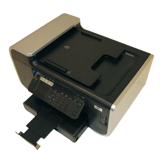
Lexmark Pro700 Series 5. Locations and connectors Locations Front view Number Part Function Scanner lid Allows access to the scanner glass Scanner glass Scans and copies photos and documents Automatic document feeder (ADF) Scans, copies, or faxes multiple-page letter-, legal-, and... -
Page 70: Rear View
Lexmark Pro700 Series Rear view Number Part Function Scanner unit Accesses the ink tanks Printhead Installs, replaces, or removes the ink tanks Ethernet port Connects the printer to a computer, a local network, an external DSL, or a cable modem... -
Page 71: System Board
Lexmark Pro700 Series System board USB-backside Locations and connectors... -
Page 72: System Board Connections
Lexmark Pro700 Series System board connections Connector Description Pin number Value Paper pick motor 1 & 2 30 V Transport carrier motor 1 & 2 30 V Paper feed motor 1 & 2 30 V Power supply 30 V Scanner motor... -
Page 73: Ina Card
Lexmark Pro700 Series INA card INA card connections Connector Description Pin number Value INA card Locations and connectors... -
Page 74: Rfid Card
Lexmark Pro700 Series RFID card (under shield) RFID card connections Connector Description Pin number Value Service Manual... -
Page 75: Fax Card
Lexmark Pro700 Series Fax card Fax card connections Connector Description Pin number Value Speaker System board Locations and connectors... -
Page 76: Preventive Maintenance
Lexmark Pro700 Series 6. Preventive maintenance This chapter describes procedures for printer preventive maintenance. Follow these recommendations to help prevent problems and maintain optimum performance. Lubrication specifications Lubricate only when parts are replaced or as needed, not on a scheduled basis. Use grease to lubricate the following: •... -
Page 77: Parts Catalog
Lexmark Pro700 Series 7. Parts catalog How to use this parts catalog The following legend is used in the parts catalog: Asm- Units/ Units/ Description Index mach • Asm-index: Identifies the assembly and the item in the diagram. For example, 2-1 indicates assembly 2 and item number 1. -
Page 78: Assembly 1: Covers
Lexmark Pro700 Series Assembly 1: Covers Service Manual... - Page 79 Lexmark Pro700 Series Assembly 1: Covers Asm- Units/ Units/ Description Index mach ADF input tray ADF cover Scanner lid assembly Module comp scanner assembly INA wireless card US/ROW INA wireless card EU/AS/J Midframe cover/operator panel Operator panel insert Operator panel overlay (English)
-
Page 80: Assembly 2: Electronics
Lexmark Pro700 Series Assembly 2: Electronics Service Manual... - Page 81 Lexmark Pro700 Series Asm- Units/ Units/ Description Index mach Module, duplex assembly Rear cover RFID card Fax card assembly Print engine assembly System board (Pro705) Right side cover Output extender Paper pick rollers Front cover Paper tray Left side cover...
-
Page 82: Index
Lexmark Pro700 Series Index 1-12 Acronyms Diagnostic aids Test mode Diagnostic information POST 2-11 Service checks 2-12 Carrier 2-11 CIS module assembly 2-11 System board Troubleshooting tables Error code table General information Copy specifications Media specifications Print specifications Scanner specifications...