Vaisala K-PATENTS PR-23-GC Manuals
Manuals and User Guides for Vaisala K-PATENTS PR-23-GC. We have 2 Vaisala K-PATENTS PR-23-GC manuals available for free PDF download: User Manual, Instruction Manual
Vaisala K-PATENTS PR-23-GC User Manual (272 pages)
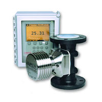
Process Refractometer
Brand: Vaisala
|
Category: Measuring Instruments
|
Size: 22 MB
Table of Contents
-
-
-
Prism Wash39
-
-
Startup52
-
-
-
-
Hardware87
-
-
-
11 Safe-Drive
172 -
-
Compatibility224
-
Specifications225
-
-
-
-
Advertisement
Vaisala K-PATENTS PR-23-GC Instruction Manual (246 pages)
Process Refractometer
Brand: Vaisala
|
Category: Measuring Instruments
|
Size: 9 MB
Table of Contents
-
-
Startup41
-
-
-
QF Threshold54
-
Wash Cycle65
-
-
Hardware73
-
Message80
-
Measurement81
-
Wash83
-
-
-
Equipment144
-
Installation146
-
Equipment148
-
-
Compatibility155
-
Model Code157
-
Specifications158
-
Model Code162
-
Dimensions163
-
Wiring168
-
Specifications172
-
-
11 Safe-Drive
175-
Specifications176
-
Parts Lists177
-
PR-23-SD Sensor177
-
Mounting180
-
Wiring186
-
Sensor Insertion193
-
Sensor Removal196
-
-
Remote Panel213
-
B Index
233