Suzuki GRAND VITARA JB416 Parts Catalog Manuals
Manuals and User Guides for Suzuki GRAND VITARA JB416 Parts Catalog. We have 3 Suzuki GRAND VITARA JB416 Parts Catalog manuals available for free PDF download: Owner's Manual, Service Manual, Manual
Suzuki GRAND VITARA JB416 Owner's Manual (1736 pages)
GRAND VITARA
Brand: Suzuki
|
Category: Automobile
|
Size: 68 MB
Table of Contents
-
Symbols25
-
Precautions33
-
Special Tool47
-
Engine49
-
Precautions55
-
Precautions56
-
DTC Check83
-
DTC Table85
-
Wiring Diagram112
-
Troubleshooting305
-
Special Tool311
-
Specifications317
-
Special Tool317
-
Specifications334
-
Specifications397
-
Special Tool398
-
For J20 Engine400
-
Specifications463
-
Special Tool464
-
Specifications476
-
Special Tool476
-
For J20 Engine477
-
Special Tool486
-
Inspection496
-
Specifications500
-
Fuel System501
-
Precautions501
-
Specifications522
-
Special Tool523
-
Ignition System524
-
Specifications534
-
Starting System535
-
Precautions535
-
Specifications544
-
Charging System545
-
Specifications560
-
Exhaust System561
-
Specifications566
-
Suspension567
-
Precautions569
-
Specifications572
-
Front Suspension573
-
Special Tool596
-
Rear Suspension597
-
Lower Arm Check613
-
Upper Arm Check615
-
Wheels and Tires630
-
Tire Rotation634
-
Tire Repair635
-
Specifications636
-
Driveline / Axle637
-
Precautions640
-
Front641
-
Specifications646
-
Special Tool646
-
Rear647
-
Specifications649
-
Special Tool649
-
Differential650
-
Front650
Advertisement
Suzuki GRAND VITARA JB416 Service Manual (475 pages)
Brand: Suzuki
|
Category: Automobile
|
Size: 13 MB
Table of Contents
-
Engine13
-
Pending DTC21
-
DTC Table37
-
DTC Check45
-
Suspension91
-
Side Slip95
-
Specifications113
-
Driveline / Axle115
-
Transfer118
-
Transfer Warning118
-
Retry Control121
-
DTC Check136
-
DTC Clearance137
-
DTC Table137
-
Fail-Safe Table138
-
Scan Tool Data139
-
Installation175
-
Suzuki GRAND VITARA JB416 Manual (35 pages)
Brand: Suzuki
|
Category: Automobile
|
Size: 0 MB
Table of Contents
-
-
-
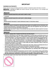
Precautions
34
Advertisement