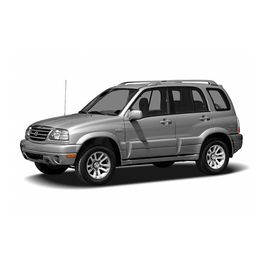
Suzuki GRAND VITARA 2005 Manual
Hide thumbs Also See for GRAND VITARA 2005:

Advertisement

Volume 1
Precautions............................................................... 00-i
Precautions ............................................................ 00-1
General Information ................................................... 0-i
General Information ............................................... 0A-1
Maintenance and Lubrication ................................. 0B-1
Engine ......................................................................... 1-i
Precautions .............................................................. 1-1
Engine General Information and Diagnosis ........... 1A-1
Aux. Emission Control Devices .............................. 1B-1
Engine Electrical Devices.......................................1C-1
Engine Mechanical.................................................1D-1
Engine Lubrication System .................................... 1E-1
Engine Cooling System.......................................... 1F-1
Fuel System ...........................................................1G-1
Ignition System.......................................................1H-1
Starting System....................................................... 1I-1
Charging System.....................................................1J-1
Exhaust System ..................................................... 1K-1
Suspension................................................................. 2-i
Precautions .............................................................. 2-1
Suspension General Diagnosis.............................. 2A-1
Front Suspension ................................................... 2B-1
Rear Suspension....................................................2C-1
Wheels and Tires ...................................................2D-1
Driveline / Axle ........................................................... 3-i
Precautions .............................................................. 3-1
Drive Shaft / Axle ................................................... 3A-1
Differential .............................................................. 3B-1
Transfer..................................................................3C-1
Propeller Shaft .......................................................3D-1
Brakes ......................................................................... 4-i
Precautions .............................................................. 4-1
Brake Control System and Diagnosis .................... 4A-1
Front Brakes........................................................... 4B-1
Rear Brakes ...........................................................4C-1
Parking Brake.........................................................4D-1
ABS ........................................................................ 4E-1
Electronic Stability Program ................................... 4F-1
TABLE OF CONTENTS
Precautions............................................................... 00-i
Precautions ............................................................ 00-1
Transmission / Transaxle .......................................... 5-i
Precautions .............................................................. 5-1
Automatic Transmission/Transaxle ........................5A-1
Manual Transmission/Transaxle ............................5B-1
Clutch .....................................................................5C-1
Steering ....................................................................... 6-i
Precautions .............................................................. 6-1
Steering General Diagnosis ...................................6A-1
Steering Wheel and Column ..................................6B-1
Power Assisted Steering System ...........................6C-1
HVAC ........................................................................... 7-i
Precautions .............................................................. 7-1
Heater and Ventilation............................................7A-1
Air Conditioning System .........................................7B-1
Restraint...................................................................... 8-i
Precautions .............................................................. 8-1
Seat Belts...............................................................8A-1
Air Bag System ......................................................8B-1
Body, Cab and Accessories ...................................... 9-i
Precautions .............................................................. 9-1
Wiring Systems ......................................................9A-1
Lighting Systems ....................................................9B-1
Instrumentation / Driver Info. / Horn .......................9C-1
Wipers / Washers ...................................................9D-1
Glass / Windows / Mirrors ......................................9E-1
Security and Locks ................................................. 9F-1
Seats ..................................................................... 9G-1
Interior Trim ............................................................9H-1
Sun Roof / T-Top / Convertible Top ........................ 9I-1
Hood / Fenders / Doors .......................................... 9J-1
Body Structure .......................................................9K-1
Paint / Coatings ...................................................... 9L-1
Exterior Trim.......................................................... 9M-1
Control Systems....................................................... 10-i
Precautions ............................................................ 10-1
Cruise Control System .........................................10A-1
Body Electrical Control System ............................10B-1
Immobilizer Control System .................................10C-1
Keyless Start System ...........................................10E-1
Volume 2
00
0
1
2
3
4
5
6
7
8
9
10
11

Advertisement

Table of Contents
loading

Summary of Contents for Suzuki GRAND VITARA 2005

  • Page 1 TABLE OF CONTENTS Volume 1 Volume 2 Precautions............... 00-i Precautions............... 00-i Precautions ............00-1 Precautions ............00-1 General Information ........... 0-i Transmission / Transaxle .......... 5-i General Information ..........0A-1 Precautions .............. 5-1 Maintenance and Lubrication ......... 0B-1 Automatic Transmission/Transaxle ......5A-1 Manual Transmission/Transaxle ......5B-1 Engine .................
  • Page 3: Table Of Contents

    Table of Contents 00- i Section 00 Precautions CONTENTS Precautions ..........00-1 Precautions for Electrical Circuit Service .... 00-9 Precautions for Installing Mobile Precautions............00-1 Communication Equipment ......00-11 Precautions for Vehicles Equipped with a Air Bag Warning ..........00-11 Supplemental Restraint (Air Bag) System ..00-1 Discharge Headlight Warning ......
  • Page 4: Precautions

    • If the air bag system and another vehicle 3. Contact coil assembly 11. Side-sensor (if equipped) system both need repair, SUZUKI 4. Air bag harness in main harness 12. Seat belt pretensioner recommends that the air bag system be 5.
  • Page 5 Precautions: 00-2 Diagnosis Servicing and Handling • When troubleshooting air bag system, be sure to WARNING follow “Air Bag Diagnostic System Check in Section 8B”. Bypassing these procedures may result in Many of service procedures require extended diagnostic time, incorrect diagnosis, and disconnection of “A/B”...
  • Page 6 00-3 Precautions: • Never dispose of live (undeployed) air bag WARNING (inflator) modules (driver, passenger, side Driver and Passenger Seat Belt and curtain). If disposal is necessary, be Pretensioners sure to deploy them according to deployment procedures described in “Air •...
  • Page 7: General Precautions

    Precautions: 00-4 General Precautions CAUTION S6JB0A0000002 The WARNING and CAUTION describe some general • Even when the accident was light enough precautions that you should observe when servicing a not to cause air bags to activate, be sure to vehicle. These general precautions apply to many of the inspect system parts and other related service procedures, and they will not necessarily be parts according to instructions under...
  • Page 8 00-5 Precautions: – For vehicle equipped with power sliding CAUTION roof (sunroof), initialize sliding roof • Before starting any service work, cover position data in motor unit by fenders, seats and any other parts that are performing “How to reactivate the likely to get scratched or stained during system to prevent being pinched by the servicing.
  • Page 9 • When use of a certain type of lubricant, bond or sealant is specified, be sure to remove the old one thoroughly and use the specified type. “A”: Sealant 99000–31150 (SUZUKI Bond No.1207C) I2RH01010033-01 • When servicing fuel system, be sure to observe WARNING in “Precautions on Fuel...
  • Page 10: Precaution In Servicing Full-Time 4Wd Vehicle

    00-7 Precautions: • Use care not to expose connectors and Precaution in Servicing Full-Time 4WD Vehicle S6JB0A0000003 electrical parts to water which will be a WARNING cause of a trouble. This full-time 4WD vehicle can not be converted to 2WD manually. Observe the following caution in servicing.
  • Page 11 Precautions: 00-8 • When testing with 2-wheel brake tester, be • When testing with 4-wheel free chassis sure to observe the following instructions. dynamometer or speedometer tester Otherwise, drive train damage and (which tester roller is driven by vehicle personal injury may result. wheels), be sure to shift transfer to 4H- Lock position according to the step 4) in –...
  • Page 12: Precaution For Vehicle Equipped With Esp® System

    00-9 Precautions: Precaution for CAN Communication System Precaution for Vehicle Equipped with ESP® S6JB0A0000006 System • The loose (1) in the wire harnesses twist of the CAN S6JB0A0000004 lines except around the connector (3) should be within • When testing with any of the following equipments 100 mm (3.9 in.).
  • Page 13 Precautions: 00-10 • When disconnecting and connecting coupler, make • When installing vehicle parts, be careful so that the sure to turn ignition switch OFF, or electronic parts wiring harness is not interfered with or caught by any may get damaged. other part.
  • Page 14: Precautions For Installing Mobile Communication Equipment

    Restraint (Air Bag) System: • Service on and around the air bag system components or wiring must be performed only by an authorized SUZUKI dealer. Refer to “Air Bag System Components, Wiring and Connectors Location in Section 8B” in order to confirm whether you are performing service on or near the air bag system components or wiring.
  • Page 15: A/C System Caution

    Precautions: 00-12 A/C System Caution Suspension Caution S6JB0A0000011 S6JB0A0000013 CAUTION CAUTION The air conditioning system of this vehicle • All suspension fasteners are an important uses refrigerant HFC-134a (R-134a). attaching part in that it could affect the None of refrigerant, compressor oil and performance of vital parts and systems, component parts is interchangeable between and/or could result in major repair...
  • Page 16: Brakes Caution And Note

    00-13 Precautions: Brakes Caution and Note NOTE S6JB0A0000015 Before inspecting and servicing brakes for CAUTION vehicle equipped with ABS (ESP®), make All brake fasteners are important attaching sure that ABS (ESP®) is in good condition. parts in that they could affect the performance of vital parts and systems, and/ Differential Gear Oil Note or could result in major repair expense.
  • Page 17 Precautions: 00-14 Continuity Check Voltage Check If voltage is supplied to the circuit being checked, voltage 1) Measure resistance between connector terminals at check can be used as circuit check. both ends of the circuit being checked (between “A- 1” and “C-1” in the figure). If no continuity is indicated 1) With all connectors connected and voltage applied to (infinity or over limit), that means that the circuit is the circuit being checked, measure voltage between...
  • Page 18 00-15 Precautions: Short Circuit Check (Wire Harness to Ground) 4) Disconnect the connector included in circuit (connector B) and measure resistance between “A- 1) Disconnect negative cable at battery. 1” and body ground. 2) Disconnect connectors at both ends of the circuit to If continuity is indicated, it means that the circuit is be checked.
  • Page 19: Intermittent And Poor Connection Inspection

    Precautions: 00-16 Intermittent and Poor Connection Inspection • Poor terminal-to-wire connection. S6JB0A0006002 Check each wire harness in problem circuits for poor Most intermittent are caused by faulty electrical connection by shaking it by hand lightly. If any connections or wiring, although a sticking relay or abnormal condition is found, repair or replace.
  • Page 20 00-17 Precautions:...
  • Page 21 Table of Contents 0- i Section 0 General Information CONTENTS General Information ........ 0A-1 Air Cleaner Filter Replacement ......0B-10 Fuel Lines and Connections Inspection ....0B-10 General Description ..........0A-1 Fuel Filter Replacement (Petrol Engine Abbreviations ............0A-1 Model) .............0B-11 Symbols .............. 0A-2 Fuel Filter Replacement (Diesel Engine Wire Color Symbols ..........
  • Page 22 0-ii Table of Contents Recommended Fluids and Lubricants (Diesel Special Tool (Petrol Engine Model)....0B-20 Engine Model) ..........0B-20...
  • Page 23: General Information

    General Information: 0A-1 General Information General Information General Description Abbreviations S6JB0A0101001 EBCM: Electronic Brake Control Module, ABS Control Module ABDC: After Bottom Dead Center EBD: Electronic Brake Force Distribution ABS: Anti-lock Brake System ECM: Engine Control Module AC: Alternating Current ECT Sensor: Engine Coolant Temperature Sensor A/C: Air Conditioning (Water Temp.
  • Page 24: Symbols

    Max: Maximum Apply fluid MFI: Multiport Fuel Injection (Multipoint Fuel Injection) (brake, power steering, automatic fluid) MIL: Malfunction Indicator Lamp (“SERVICE ENGINE Apply SUZUKI SUPER GREASE A SOON” Light) 99000-25011 Min: Minimum Apply SUZUKI SUPER GREASE C M/T: Manual Transmission...
  • Page 25: Wire Color Symbols

    General Information: 0A-3 Wire Color Symbols There are two kinds of colored wire used in this vehicle. S6JB0A0101003 One is single-colored wire and the other is dual-colored Symbol Wire Color (striped) wire. As the color symbol, the single-colored Black wire uses only one, three or five alphabets (i.e. “G” or Blue “GRN”);...
  • Page 26 0A-4 General Information: Fastener Strength Identification Most commonly used metric fastener strength property classes are 4T, 6.8, 7T, 8.8 and radial line with the class identification embossed on the head of each bolt. Some metric nuts will be marked with punch, 6 or 8 mark strength identification on the nut face.
  • Page 27 General Information: 0A-5 Standard Tightening Torque Each fastener should be tightened to the torque specified in each section of this manual. If no description or specification is provided, refer to the following tightening torque chart for the applicable torque for each fastener. When a fastener of greater strength than the original one is used, however, use the torque specified for the original fastener.
  • Page 28: Vehicle Lifting Points

    0A-6 General Information: Vehicle Lifting Points S6JB0A0101005 WARNING • Before applying hoist to underbody, always take vehicle balance throughout service into consideration. Vehicle balance on hoist may change depending of what part to be removed. • Before lifting up the vehicle, check to be sure that end of hoist arm is not in contact with brake pipe, fuel pipe, bracket or any other part.
  • Page 29 General Information: 0A-7 When using floor jack To perform service with either front or rear vehicle end jacked up, be sure to place safety stands (1) under WARNING chassis frame so that body is securely supported. And then check to ensure that chassis frame does not •...
  • Page 30: Engine Supporting Points

    0A-8 General Information: Engine Supporting Points Vehicle Identification Number S6JB0A0101006 S6JB0A0101007 The vehicle identification number is punched on the front WARNING dash panel in engine room and it is also attached on the When using engine supporting device (1), be left front top of instrument panel depending on vehicle sure to observe the followings.
  • Page 31: Engine Identification Number

    General Information: 0A-9 Engine Identification Number Transmission Identification Number S6JB0A0101008 S6JB0A0101009 The number is punched on the cylinder block. The number is located on the transmission case. I6JB0A010001-01 [A]: Petrol engine model I6JB0A010002-01 [B]: Diesel engine model [A]: M/T (Petrol engine model) [B]: 4A/T [C]: M/T (Diesel engine model)
  • Page 32: Component Location

    0A-10 General Information: Component Location Warning, Caution and Information Label Location S6JB0A0103001 The figure shows main labels among others that are attached to vehicle component parts. When servicing and handling parts, refer to WARNING / CAUTION instructions printed on labels. If any WARNING / CAUTION label is found stained or damaged, clean or replace it as necessary.
  • Page 33 General Information: 0A-11 I5JB0A010009-03 1. Air bag label on driver air bag (inflator) module 4. Air bag label on passenger air bag (inflator) module 7. Air bag label on side air bag module 2. Air bag label on contact coil assembly 5.
  • Page 34: Maintenance And Lubrication

    0B-1 Maintenance and Lubrication: Maintenance and Lubrication General Information Precautions Precautions for Maintenance and Lubrication S6JB0A0200001 Air Bag Warning Refer to “Air Bag Warning in Section 00”. Scheduled Maintenance Maintenance Schedule under Normal Driving Conditions (Petrol Engine Model) S6JB0A0205001 NOTE •...
  • Page 35: Change

    Maintenance and Lubrication: 0B-2 Km (x 1,000) Interval Miles (x 1,000) Months Chassis and body Clutch (fluid leakage, level) (I: — — — Tires (wear, damage, rotation) / wheels (damage) (I: Suspension system (tightness, damage, rattle, breakage) (I: — — —...

Table of Contents