Sign In
Upload
Manuals
Brands
Renesas Manuals
Motherboard
RX Series
Renesas RX Series Microcontroller Board Manuals
Manuals and User Guides for Renesas RX Series Microcontroller Board. We have
18
Renesas RX Series Microcontroller Board manuals available for free PDF download: User Manual, Application Note
Renesas MCB-RX26T Type C, RX Series, RX26T Series, RX200 Series Manual
Brand:
Renesas
| Category:
Computer Hardware
| Size: 0 MB
Table of Contents
General Precautions in the Handling of Microprocessing Unit and Microcontroller Unit Products
Overview
Presupposition and precautions of this document
Product Contents
Product Order Information
Hardware Configuration and Default Setting
Hardware configuration
Block diagram
Board Layout
Standoffs and Screws
Jumper pin setting
Hardware Setup
CPU Board Specification
Functions
Power supply
On-board debugger
Inverter board connector
Serial communication
Reset circuit
LED
CAN Communication
SPI Communication
Pmod
RX26T pin function list
Design and Manufacture Information
Website and Support
Documents / Resources
References
Advertisement
Renesas RX Series User Manual (1823 pages)
32-Bit MCU
Brand:
Renesas
| Category:
Microcontrollers
| Size: 23 MB
Table of Contents
Table of Contents
7
Features
51
Overview
52
Outline of Specifications
52
List of Products
57
Block Diagram
58
Pin Functions
59
Pin Assignments
63
Cpu
69
Features
69
Register Set of the CPU
70
General-Purpose Registers (R0 to R15)
71
Control Registers
71
Interrupt Stack Pointer (Isp)/User Stack Pointer (USP)
72
Exception Table Register (EXTB)
72
Interrupt Table Register (INTB)
72
Program Counter (PC)
72
Processor Status Word (PSW)
73
Backup PC (BPC)
74
Backup PSW (BPSW)
75
Fast Interrupt Vector Register (FINTV)
75
Floating-Point Status Word (FPSW)
76
Accumulator
78
Processor Mode
79
Supervisor Mode
79
User Mode
79
Privileged Instruction
79
Switching between Processor Modes
79
Data Types
80
Integer
80
Floating-Points
81
Bitwise Operations
81
Strings
82
Endian
83
Switching the Endian
83
Access to I/O Registers
86
Notes on Access to I/O Registers
86
Data Arrangement
87
Data Arrangement in Registers
87
Data Arrangement in Memory
87
Notes on the Allocation of Instruction Codes
87
Vector Table
88
Exception Vector Table
88
Interrupt Vector Table
89
Operation of Instructions
90
Restrictions on RMPA and String-Manipulation Instructions
90
Transfer Size and Data Prefetching
90
Access to the External Space
90
Access to I/O Registers
90
Number of Cycles
91
Instruction and Number of Cycle
91
Numbers of Cycles for Response to Interrupts
95
Operating Modes
96
Operating Mode Types and Selection
96
Register Descriptions
97
Mode Monitor Register (MDMONR)
97
System Control Register 1 (SYSCR1)
98
Details of Operating Modes
99
Single-Chip Mode
99
Boot Mode
99
Boot Mode (USB Interface)
99
Boot Mode (SCI)
99
Transitions of Operating Modes
100
Operating Mode Transitions Determined by the Mode-Setting Pins
100
Address Space
101
I/O Registers
103
I/O Register Addresses (Address Order)
105
Resets
136
Overview
136
Register Descriptions
138
Reset Status Register 0 (RSTSR0)
138
Reset Status Register 1 (RSTSR1)
139
Reset Status Register 2 (RSTSR2)
140
Software Reset Register (SWRR)
141
Operation
142
RES# Pin Reset
142
Power-On Reset and Voltage Monitoring 0 Reset
142
Voltage Monitoring 1 Reset
144
Independent Watchdog Timer Reset
145
Watchdog Timer Reset
145
Software Reset
145
Determination of Cold/Warm Start
146
Determination of Reset Generation Source
147
Option-Setting Memory (OFSM)
148
Overview
148
Register Descriptions
149
Option Function Select Register 0 (OFS0)
149
Option Function Select Register 1 (OFS1)
153
Endian Select Register (MDE)
154
Usage Note
155
Setting Example of Option-Setting Memory
155
Voltage Detection Circuit (Lvdab)
156
Overview
156
Register Descriptions
158
Voltage Monitoring 1 Circuit Control Register 1 (LVD1CR1)
158
Voltage Monitoring 1 Circuit Status Register (LVD1SR)
159
Voltage Monitoring Circuit Control Register (LVCMPCR)
160
Voltage Detection Level Select Register (LVDLVLR)
161
Voltage Monitoring 1 Circuit Control Register 0 (LVD1CR0)
162
VCC Input Voltage Monitor
163
Monitoring Vdet0
163
Monitoring Vdet1
163
Reset from Voltage Monitor 0
164
Interrupt and Reset from Voltage Monitoring 1
165
Event Link Output
167
Interrupt Handling and Event Linking
167
Clock Generation Circuit
168
Overview
168
Register Descriptions
172
System Clock Control Register (SCKCR)
172
System Clock Control Register 3 (SCKCR3)
174
PLL Control Register (PLLCR)
175
PLL Control Register 2 (PLLCR2)
176
USB-Dedicated PLL Control Register (UPLLCR)
177
USB-Dedicated PLL Control Register 2 (UPLLCR2)
178
Main Clock Oscillator Control Register (MOSCCR)
179
Sub-Clock Oscillator Control Register (SOSCCR)
180
Low-Speed On-Chip Oscillator Control Register (LOCOCR)
181
IWDT-Dedicated On-Chip Oscillator Control Register (ILOCOCR)
182
High-Speed On-Chip Oscillator Control Register (HOCOCR)
183
High-Speed On-Chip Oscillator Control Register 2 (HOCOCR2)
184
Oscillation Stabilization Flag Register (OSCOVFSR)
185
Oscillation Stop Detection Control Register (OSTDCR)
187
Oscillation Stop Detection Status Register (OSTDSR)
188
Main Clock Oscillator Wait Control Register (MOSCWTCR)
189
CLKOUT Output Control Register (CKOCR)
190
Main Clock Oscillator Forced Oscillation Control Register (MOFCR)
191
Memory Wait Cycle Setting Register (MEMWAIT)
192
Low-Speed On-Chip Oscillator Trimming Register (LOCOTRR)
194
IWDT-Dedicated On-Chip Oscillator Trimming Register (ILOCOTRR)
194
High-Speed On-Chip Oscillator Trimming Register N (Hocotrrn) (N = 0, 3)
195
Main Clock Oscillator
196
Connecting a Crystal
196
External Clock Input
197
Handling of Pins When the Main Clock Is Not Used
197
Notes on the External Clock Input
197
Sub-Clock Oscillator
198
Connecting 32.768-Khz Crystal
198
Handling of Pins When Sub-Clock Is Not Used
199
Dedicated Clock Oscillator for Bluetooth
200
Connecting the Oscillator
200
Connecting the Bluetooth-Dedicated Clock Output Pin
200
Oscillation Stop Detection Function
201
Oscillation Stop Detection and Operation after Detection
201
Oscillation Stop Detection Interrupts
202
PLL Circuit
203
Internal Clock
203
System Clock
203
Peripheral Module Clock
203
Flashif Clock
203
USB Clock
204
CAN Clock
204
CAC Clock
204
RTC-Dedicated Clock
204
IWDT-Dedicated Clock
204
SSI Clock
204
Clocks for BLE
204
Low-Power Timer Clock
204
Usage Notes
205
Notes on Clock Generation Circuit
205
Notes on Resonator
205
Notes on Board Design
205
Notes on Resonator Connection Pins
206
Notes on Sub-Clock
206
Clock Frequency Accuracy Measurement Circuit (CAC)
210
Overview
210
Register Descriptions
212
CAC Control Register 0 (CACR0)
212
CAC Control Register 1 (CACR1)
213
CAC Control Register 2 (CACR2)
214
CAC Interrupt Request Enable Register (CAICR)
215
CAC Status Register (CASTR)
216
CAC Upper-Limit Value Setting Register (CAULVR)
217
CAC Lower-Limit Value Setting Register (CALLVR)
217
CAC Counter Buffer Register (CACNTBR)
217
Operation
218
Measuring Clock Frequency
218
Digital Filtering of Signals on the CACREF Pin
219
Interrupt Requests
219
Usage Notes
220
Module Stop Function Setting
220
Low Power Consumption
221
Overview
221
Register Descriptions
225
Standby Control Register (SBYCR)
225
Module Stop Control Register a (MSTPCRA)
226
Module Stop Control Register B (MSTPCRB)
227
Module Stop Control Register C (MSTPCRC)
229
Module Stop Control Register D (MSTPCRD)
230
Operating Power Control Register (OPCCR)
231
Sub Operating Power Control Register (SOPCCR)
232
Sleep Mode Return Clock Source Switching Register (RSTCKCR)
237
Reducing Power Consumption by Switching Clock Signals
239
Module Stop Function
239
Function for Lower Operating Power Consumption
239
Setting Operating Power Control Mode
239
Low Power Consumption Modes
241
Sleep Mode
241
Entry to Sleep Mode
241
Exit from Sleep Mode
242
Sleep Mode Return Clock Source Switching Function
242
Deep Sleep Mode
243
Entry to Deep Sleep Mode
243
Exit from Deep Sleep Mode
244
Software Standby Mode
245
Entry to Software Standby Mode
245
Exit from Software Standby Mode
246
Example of Software Standby Mode Application
247
Usage Notes
248
I/O Port States
248
Module Stop State of DMAC and DTC
248
On-Chip Peripheral Module Interrupts
248
Write Access to MSTPCRA, MSTPCRB, MSTPCRC, and MSTPCRD
248
Timing of WAIT Instructions
248
Rewrite the Register by DMAC and DTC in Sleep Mode
248
Battery Backup Function
249
Overview
249
Register Descriptions
250
VBATT Control Register (VBATTCR)
250
VBATT Status Register (VBATTSR)
251
VBATT Pin Voltage Drop Detection Interrupt Control Register (VBTLVDICR)
252
Operation
253
Battery Backup Function
253
VBATT Pin Voltage Monitoring Function
254
Usage Notes
255
Register Write Protection Function
256
Register Descriptions
257
Protect Register (PRCR)
257
Exception Handling
258
Exception Events
258
Undefined Instruction Exception
259
Privileged Instruction Exception
259
Access Exceptions
259
Floating-Point Exception
259
Reset
259
Non-Maskable Interrupt
259
Interrupt
259
Unconditional Trap
259
Exception Handling Procedure
260
Acceptance of Exception Events
262
Acceptance Timing and Saved PC Value
262
Vector and Site for Saving the Values in the PC and PSW
263
Hardware Processing for Accepting and Returning from Exceptions
264
Hardware Pre-Processing
265
Undefined Instruction Exception
265
Privileged Instruction Exception
265
Access Exceptions
265
Floating-Point Exception
265
Reset
265
Non-Maskable Interrupt
266
Interrupt
266
Unconditional Trap
266
Return from Exception Handling Routine
267
Priority of Exception Events
267
Interrupt Controller (Icub)
268
Overview
268
Register Descriptions
270
Interrupt Request Register N (Irn) (N = Interrupt Vector Number)
270
Interrupt Request Enable Register M (Ierm) (M = 02H to 1Fh)
271
Interrupt Source Priority Register N (Iprn) (N = Interrupt Vector Number)
272
Fast Interrupt Set Register (FIR)
273
Software Interrupt Generation Register (SWINTR)
274
DTC Transfer Request Enable Register N (Dtcern) (N = Interrupt Vector Number)
275
DMAC Trigger Select Register M (Dmrsrm) (M = DMAC Channel Number)
276
IRQ Control Register I (Irqcri) (I = 0, 1, and 4 to 7)
277
IRQ Pin Digital Filter Enable Register 0 (IRQFLTE0)
278
IRQ Pin Digital Filter Setting Register 0 (IRQFLTC0)
279
Non-Maskable Interrupt Status Register (NMISR)
280
Non-Maskable Interrupt Enable Register (NMIER)
282
Non-Maskable Interrupt Status Clear Register (NMICLR)
284
NMI Pin Interrupt Control Register (NMICR)
285
NMI Pin Digital Filter Enable Register (NMIFLTE)
285
NMI Pin Digital Filter Setting Register (NMIFLTC)
286
Vector Table
287
Interrupt Vector Table
287
Fast Interrupt Vector Table
293
Non-Maskable Interrupt Vector Area
293
Interrupt Operation
294
Detecting Interrupts
294
Operation of Status Flags for Edge-Detected Interrupts
294
Operation of Status Flags for Level-Detected Interrupts
296
Enabling and Disabling Interrupt Sources
297
Selecting Interrupt Request Destinations
298
Determining Priority
300
Multiple Interrupts
300
Fast Interrupt
300
Digital Filter
301
External Pin Interrupts
301
Non-Maskable Interrupt Operation
302
Return from Power-Down States
303
Return from Sleep Mode or Deep Sleep Mode
303
Return from Software Standby Mode
303
Usage Note
304
Note on WAIT Instruction Used with Non-Maskable Interrupt
304
Buses
305
Overview
305
Description of Buses
307
CPU Buses
307
Memory Buses
307
Internal Main Buses
307
Internal Peripheral Buses
308
Write Buffer Function (Internal Peripheral Bus)
309
Parallel Operation
310
Register Descriptions
311
Bus Error Status Clear Register (BERCLR)
311
Bus Error Monitoring Enable Register (BEREN)
311
Bus Error Status Register 1 (BERSR1)
312
Bus Error Status Register 2 (BERSR2)
312
Bus Priority Control Register (BUSPRI)
313
Bus Error Monitoring Section
315
Types of Bus Error
315
Illegal Address Access
315
Timeout
315
Operations When a Bus Error Occurs
316
Conditions Leading to Bus Errors
316
Interrupt
317
Interrupt Source
317
Memory-Protection Unit (MPU)
318
Overview
318
Types of Access Control
320
Regions for Access Control
320
Background Region
320
Overlap between Regions
320
Instructions and Data that Span Regions
320
Register Descriptions
321
Region-N Start Page Number Register (Rspagen) (N = 0 to 7)
321
Region-N End Page Number Register (Repagen) (N = 0 to 7)
322
Memory-Protection Enable Register (MPEN)
323
Background Access Control Register (MPBAC)
324
Memory-Protection Error Status-Clearing Register (MPECLR)
325
Memory-Protection Error Status Register (MPESTS)
326
Data Memory-Protection Error Address Register (MPDEA)
327
Region Search Address Register (MPSA)
327
Region Search Operation Register (MPOPS)
328
Region Invalidation Operation Register (MPOPI)
328
Instruction-Hit Region Register (MHITI)
329
Data-Hit Region Register (MHITD)
331
Functions
333
Memory Protection
333
Region Search
333
Protection of Registers Related to the Memory-Protection Unit
333
Flow for Determination of Access by the Memory-Protection Function
334
Procedures for Using Memory Protection
336
Setting Access-Control Information
336
Enabling Memory Protection
336
Transition to User Mode
336
Processing in Response to Memory-Protection Errors
336
DMA Controller (DMACA)
338
Overview
338
Register Descriptions
340
DMA Source Address Register (DMSAR)
340
DMA Destination Address Register (DMDAR)
340
DMA Transfer Count Register (DMCRA)
341
DMA Block Transfer Count Register (DMCRB)
343
DMA Transfer Mode Register (DMTMD)
344
DMA Interrupt Setting Register (DMINT)
345
DMA Address Mode Register (DMAMD)
347
DMA Offset Register (DMOFR)
350
DMA Transfer Enable Register (DMCNT)
351
DMA Software Start Register (DMREQ)
352
DMA Status Register (DMSTS)
353
DMA Activation Source Flag Control Register (DMCSL)
355
DMA Module Activation Register (DMAST)
356
Operation
357
Transfer Mode
357
Extended Repeat Area Function
361
Address Update Function Using Offset
363
Activation Sources
367
Operation Timing
368
DMAC Execution Cycles
369
Activating the DMAC
370
Starting DMA Transfer
371
Registers During DMA Transfer
371
Channel Priority
372
Ending DMA Transfer
373
Transfer End by Completion of Specified Total Number of Transfer Operations
373
Transfer End by Repeat Size End Interrupt
373
Transfer End by Interrupt on Extended Repeat Area Overflow
374
Interrupts
375
Event Link Function
376
Low Power Consumption Function
377
Usage Notes
378
DMA Transfer to Peripheral Modules
378
Access to the Registers During DMA Transfer
378
DMA Transfer to Reserved Areas
378
Interrupt Request by the DMA Activation Source Flag Control Register (DMCSL) at the End of each Transfer
378
Setting of DMAC Activation Source Select Register of the Interrupt Controller (Icu.dmrsrm)
378
Suspending or Restarting DMA Activation
378
Data Transfer Controller (Dtca)
379
Overview
379
Register Descriptions
381
DTC Mode Register a (MRA)
381
DTC Mode Register B (MRB)
382
DTC Transfer Source Register (SAR)
383
DTC Transfer Destination Register (DAR)
383
DTC Transfer Count Register a (CRA)
384
DTC Transfer Count Register B (CRB)
385
DTC Control Register (DTCCR)
385
DTC Vector Base Register (DTCVBR)
386
DTC Address Mode Register (DTCADMOD)
386
DTC Module Start Register (DTCST)
387
DTC Status Register (DTCSTS)
388
Request Sources
389
Allocating Transfer Information and DTC Vector Table
389
Operation
391
Transfer Information Read Skip Function
393
Transfer Information Write-Back Skip Function
394
Normal Transfer Mode
395
Repeat Transfer Mode
396
Block Transfer Mode
397
Chain Transfer
398
Operation Timing
399
Execution Cycles of the DTC
402
DTC Bus Mastership Release Timing
402
DTC Setting Procedure
403
Examples of DTC Usage
404
Normal Transfer
404
Chain Transfer When the Counter Is 0
405
Interrupt Source
406
Event Link
406
Low Power Consumption Function
407
19.10 Usage Notes
408
Start Address of Transfer Information
408
Allocating Transfer Information
408
Setting the DTC Transfer Request Enable Register in the Interrupt Controller (Icu.dtcern)
409
Event Link Controller (ELC)
410
Overview
410
Register Descriptions
411
Event Link Control Register (ELCR)
411
Event Link Setting Register N (Elsrn) (N = 1 to 4, 7, 8, 10, 12, 14 to 16, 18 to 29)
412
Event Link Option Setting Register a (ELOPA)
415
Event Link Option Setting Register B (ELOPB)
415
Event Link Option Setting Register C (ELOPC)
416
Event Link Option Setting Register D (ELOPD)
416
Port Group Setting Register N (Pgrn) (N = 1, 2)
417
Port Group Control Register N (Pgcn) (N = 1, 2)
418
Port Buffer Register N (Pdbfn) (N = 1, 2)
419
Event Link Port Setting Register M (Pelm) (M = 0 to 3)
420
Event Link Software Event Generation Register (ELSEGR)
421
Operation
422
Relation between Interrupt Handling and Event Linking
422
Event Linkage
423
Operation of Peripheral Timer Modules When Event Signal Is Input
424
Operation of A/D and D/A Converters When Event Signal Is Input
424
I/O Port Operation When Event Signal Is Input and Event Generation
424
Example of Procedure for Linking Events
428
Usage Notes
429
Setting Elsrn Register
429
Setting Bit-Rotating Operation of Output Port Groups
429
Linking DMA/DTC Transfer End Signal as Event
429
Clock Settings
429
Module Stop Function Setting
429
I/O Ports
430
Overview
430
I/O Port Configuration
432
Register Descriptions
441
Port Direction Register (PDR)
441
Port Output Data Register (PODR)
442
Port Input Data Register (PIDR)
443
Port Mode Register (PMR)
444
Renesas RX Series User Manual (60 pages)
Starter Kit+ 32-Bit MCU
Brand:
Renesas
| Category:
Control Unit
| Size: 1 MB
Table of Contents
Table of Contents
7
1 Overview
9
Purpose
9
Features
9
Board Specification
10
2 Power Supply
11
Requirements
11
Power-Up Behaviour
11
3 Board Layout
12
Component Layout
12
Board Dimensions
13
Component Placement
14
4 Connectivity
16
Internal Board Connections
16
Debugger Connections
17
5 User Circuitry
18
Reset Circuit
18
Clock Circuit
18
Switches
18
Leds
19
Potentiometer
19
Pmod
20
USB Serial Port
21
Controller Area Network (CAN)
21
Ethernet
22
Ethercat Slave Controller (ESC)
24
Universal Serial Bus (USB)
25
Rs-485
26
External Bus
26
Sdram
27
Renesas Serial Peripheral Interface (RSPI)
28
Quad Serial Peripheral Interface (QSPI)
28
C Bus (Inter-IC Bus)
28
SD Host Interface (SDHI)
29
Delta-Sigma Modulation Interface (DSMIF)
29
6 Configuration
30
Modifying the RSK
30
MCU Operating Modes
30
E1/E2 Lite Debugger Configuration
31
Power Supply Configuration
32
Clock Configuration
32
Analog Power, ADC and DAC Configuration
33
BUS & SDRAM Configuration
34
CAN Configuration
37
DSMIF Configuration
37
Ethercat Configuration
38
Ethernet Configuration
40
General IO & LED Configuration
42
I2C & EEPROM Configuration
43
IRQ & Switch Configuration
43
MTU & POE Configuration
44
PMOD1 Configuration
46
PMOD2 Configuration
46
QSPI Configuration
47
RS-485 Configuration
47
RSPI Configuration
47
Serial & USB to Serial Configuration
48
SDHI Configuration
49
USB Configuration
50
Advertisement
Renesas RX Series User Manual (60 pages)
Starter Kit+
Brand:
Renesas
| Category:
Microcontrollers
| Size: 1 MB
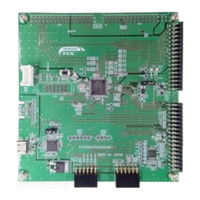
Table of Contents
Table of Contents
6
Overview
8
Purpose
8
Features
8
Board Specification
9
Power Supply
10
Requirements
10
Power-Up Behaviour
10
Board Layout
11
Component Layout
11
Board Dimensions
12
Component Placement
13
Connectivity
15
Internal RSK+ Connections
15
Debugger Connections
16
User Circuitry
17
Reset Circuit
17
Clock Circuit
17
Switches
17
Leds
17
Potentiometer
18
Pmod
18
USB Serial Port
19
Controller Area Network (CAN)
19
Ethernet
20
Universal Serial Bus (USB)
20
LCD Direct Drive Header (TFT)
21
External Bus
21
Renesas Serial Peripheral Interface (RSPI)
21
Quad Serial Peripheral Interface (QSPI)
21
I 2 C Bus (Inter-IC Bus)
21
SD Host Interface (SDHI)
21
SD Slave Interface (SDSI)
22
Parallel Data Capture Unit (PDC)
22
Configuration
23
Modifying the RSK
23
MCU Operating Modes
23
E1/E2 Lite Debugger Configuration
24
Power Supply Configuration
25
Clock Configuration
25
Analog Power & ADC & DAC Configuration
26
BUS & SDRAM Configuration
27
CAN Configuration
31
LCD Direct Drive (TFT) Configuration
31
Ethernet Configuration
35
General IO & LED Configuration
36
I2C & EEPROM Configuration
37
MTU & POE Configuration
38
IRQ & Switch Configuration
40
PDC Configuration
41
Renesas RX Series User Manual (55 pages)
Starter Kit+ For e2 studio
Brand:
Renesas
| Category:
Microcontrollers
| Size: 1 MB
Table of Contents
Table of Contents
6
Overview
8
Purpose
8
Features
8
Scope
8
Power Supply
9
Requirements
9
Power-Up Behaviour
9
Board Layout
10
Component Layout
10
Board Dimensions
11
Component Placement
12
Connectivity
14
Internal RSK+ Connections
14
Debugger Connections
15
User Circuitry
16
Reset Circuit
16
Clock Circuit
16
Switches
16
Leds
17
Potentiometer
17
Debug LCD Module
17
RS232 Serial Port
18
Controller-Area Network (CAN)
18
Ethernet
19
Universal Serial Bus (USB)
20
Generic LCD Header
21
External Bus
22
Renesas Serial Peripheral Interface (RSPI)
22
C Bus (Inter-IC Bus)
22
Configuration
23
Modifying the RSK
23
MCU Configuration
23
ADC Configuration
24
RS232 Serial Port Configuration
25
CAN Configuration
26
External Bus Configuration
27
USB Configuration
29
Ethernet Configuration
32
Multi-Function Timer Pulse Unit (MTU) Configuration
34
IRQ & General I/O Pin Configuration
35
Power Supply Configuration
37
Clock Configuration
39
External Memory Configuration
39
Headers
41
Application Headers
41
Generic Headers
46
Code Development
48
Overview
48
Compiler Restrictions
48
Mode Support
48
Debugging Support
48
Address Space
49
Additional Information
50
Renesas RX Series User Manual (64 pages)
RX23W Group. Solution Starter Kit for RX23W Smart Configurator
Brand:
Renesas
| Category:
Computer Hardware
| Size: 2 MB
Table of Contents
Table of Contents
7
Overview
8
Purpose
8
Features
8
Introduction
9
Project Creation with E Studio
10
Introduction
10
Creating the Project
10
Smart Configurator Using the E Studio
13
Introduction
13
Project Configuration Using Smart Configurator
14
The 'Board' Tabbed Page
15
Board Configuration Page
15
The 'Clocks' Tabbed Page
16
Clocks Configuration
16
The 'Components' Tabbed Page
17
Add a Software Component into the Project
17
Compare Match Timer
18
Interrupt Controller
21
Ports
23
SCI/SCIF Asynchronous Mode
27
SPI Clock Synchronous Mode
30
Single Scan Mode S12AD
33
The 'Pins' Tabbed Page
36
Change Pin Assignment of a Software Component
36
Building the Project
39
User Code Integration
40
Project Settings
40
LCD Code Integration
41
SPI Code
43
CMT Code
44
Additional Include Paths
45
Switch Code Integration
46
Interrupt Code
46
Bounce Timer Code
48
Main Switch and ADC Code
49
Debug Code Integration
52
UART Code Integration
53
SCI Code
53
Main UART Code
55
LED Code Integration
57
Debugging the Project
59
Additional Information
61
Renesas RX Series User Manual (53 pages)
Starter Kit
Brand:
Renesas
| Category:
Microcontrollers
| Size: 2 MB
Table of Contents
Table of Contents
9
1 Overview
11
Purpose
11
Features
11
Board Specification
12
2 Power Supply
13
Requirements
13
Power-Up Behaviour
13
3 Board Layout
14
Component Layout
14
Board Dimensions
15
Component Placement
16
4 Connectivity
18
Internal RSK Connections
18
Debugger Connections
19
5 User Circuitry
20
Reset Circuit
20
Clock Circuit
20
Switches
20
Leds
21
Potentiometer
21
Pmod™(Pmod1)
22
Pmod™(Pmod2)
23
USB Serial Port
24
Controller Area Network (CAN)
25
Universal Serial Bus (USB)
25
C Bus (Inter-IC Bus)
25
Touch Interface
26
6 Configuration
27
Modifying the RSK
27
MCU Operating Modes
27
Power Supply Configuration
28
Clock Configuration
28
Analog Power ADC & DAC Configuration
29
E1 Debugger Configuration
30
General I/O & LED Configuration
31
I 2 C & EEPROM Configuration
31
IRQ & Switch Configuration
32
External Bus Configuration
33
CAN Configuration
35
TPU & MTU & POE Configuration
35
PMOD1 Interface Configuration
37
PMOD2 Interface Configuration
37
Serial & USB to Serial Configuration
38
USB Configuration
39
Touch Interface Configuration
39
7 Headers
40
Application Headers
40
Microcontroller Pin Headers
46
8 Code Development
48
Renesas RX Series User Manual (45 pages)
32-Bit MCU; Renesas Starter Kit
Brand:
Renesas
| Category:
Computer Hardware
| Size: 0 MB
Table of Contents
Table of Contents
9
1 Overview
11
Purpose
11
Features
11
Board Specification
12
2 Power Supply
13
Requirements
13
Power-Up Behaviour
13
3 Board Layout
14
Component Layout
14
Board Dimensions
15
Component Placement
16
4 Connectivity
18
Internal RSK Connections
18
Debugger Connections
19
5 User Circuitry
20
Reset Circuit
20
Clock Circuit
20
Switches
20
Leds
21
Potentiometer
21
Pmod
22
USB Serial Port
23
Local-Interconnect Network (LIN)
23
C Bus (Inter-IC Bus)
24
Touch Interface
24
6 Configuration
25
Modifying the RSK
25
MCU Operating Modes
25
Power Supply Configuration
26
Clock Configuration
26
Analog Power & ADC & DAC Configuration
27
E1 / E2 Lite Debugger Configuration
27
General I/O & LED Configuration
28
I 2 C & EEPROM Configuration
28
IRQ & Switch Configuration
29
LIN Configuration
29
MTU & POE Configuration
30
PMOD1 Interface Configuration
31
PMOD2 Interface Configuration
31
Serial & USB to Serial Configuration
32
Touch Interface Configuration
33
7 Headers
34
Application Headers
34
Microcontroller Pin Headers
38
8 Code Development
40
Overview
40
Compiler Restrictions
40
Mode Support
40
Debugging Support
40
Renesas RX Series User Manual (43 pages)
Starter Kit For CubeSuite+. RX111 Group
Brand:
Renesas
| Category:
Computer Hardware
| Size: 1 MB
Table of Contents
Table of Contents
7
Overview
8
Purpose
8
Features
8
Power Supply
9
Requirements
9
Power-Up Behaviour
9
Board Layout
10
Component Layout
10
Board Dimensions
11
Component Placement
12
Connectivity
13
Internal RSK Connections
13
Debugger Connections
14
User Circuitry
15
Reset Circuit
15
Clock Circuit
15
Switches
15
Leds
16
Potentiometer
16
Pmod™ Debug LCD Module
16
USB Serial Port
17
Local Interconnect Network (LIN)
18
Universal Serial Bus (USB)
18
I 2 C Bus (Inter-IC Bus)
18
Configuration
19
Modifying the RSK
19
MCU Operating Modes
19
Power Supply Configuration
20
Clock Configuration
20
ADC & DAC Configuration
21
E1 Debugger Configuration
22
I2C EEPROM Configuration
22
I/O Port Configuration
23
IRQ & Switch Configuration
24
LIN Configuration
24
MTU & POE Configuration
25
PMOD1 Interface Configuration
27
PMOD2 Interface Configuration
28
SCI & RS232 Serial Port Configuration
29
USB Configuration
30
Headers
31
Application Headers
31
Microcontroller Pin Headers
35
Code Development
37
Overview
37
Compiler Restrictions
37
Mode Support
37
Debugging Support
37
Address Space
38
Additional Information
39
Renesas RX Series Application Note (58 pages)
Serial Communications Interface
Brand:
Renesas
| Category:
Network Hardware
| Size: 0 MB
Table of Contents
Table of Contents
2
Points of Difference between Serial Communications Interfaces
3
Points of Difference between Functions
3
Points of Difference between Registers
7
Peripheral Functions Used
18
Points of Difference in Clock-Synchronous Serial Communication
19
Points of Difference in Master Transmit/Receive Operation
19
Points of Difference in Master Transmit/Receive Operation Timing
19
Points of Difference in Setting Procedure for Master Transmit/Receive Operation
23
Points of Difference in Master Transmit Operation
26
Points of Difference in Master Transmit Operation Timing
26
Points of Difference in Setting Procedure for Master Transmit Operation
28
Points of Difference in Slave Receive Operation
30
Points of Difference in Slave Receive Operation Timing
30
Points of Difference in Setting Procedure for Slave Receive Operation
32
Points of Difference in Asynchronous Serial Communication
35
Points of Difference in Transmit Operation
36
Points of Difference in Transmit Operation Timing
36
Points of Difference in Transmit Operation Setting Procedure
38
Points of Difference in Receive Operation
40
Points of Difference in Receive Operation Timing
40
Points of Difference in Receive Operation Setting Procedure
42
Calculating the Bit Rate
45
Points of Difference between Interrupts
46
Module Stop Function
49
Register Write Protection Function
50
Key Points When Migrating from H8S to RX
51
I/O Ports
51
I/O Register Macros
52
Embedded Functions
53
Notes Regarding Transmit-Enable Bit
53
10. Reference Documents
54
Website and Support
55
Revision History
56
Renesas RX Series User Manual (53 pages)
Starter Kit+ Code Generator Tutorial Manual
Brand:
Renesas
| Category:
Portable Generator
| Size: 1 MB
Table of Contents
Table of Contents
6
1 Overview
7
Purpose
7
Features
7
2 Introduction
8
3 Project Creation with E Studio
9
Introduction
9
Creating the Project
9
4 Code Generation Using the E Studio Plug in
14
Introduction
14
Code Generator Tour
14
Code Generation
17
Building the Project
30
5 User Code Integration
31
LCD Code Integration
31
Additional Include Paths
34
Switch Code Integration
35
Debug Code Integration
41
UART Code Integration
41
LED Code Integration
45
6 Debugging the Project
47
7 Additional Information
49
Renesas RX Series User Manual (33 pages)
Target Board, 32-Bit MCU
Brand:
Renesas
| Category:
Motherboard
| Size: 1 MB
Table of Contents
Table of Contents
6
1 Overview
7
Package Components
7
Purpose
7
Features
7
Preparation
7
Target Board for RX23W: Table of Specifications
8
Block Diagram
9
2 Board Layout
10
3 Parts Layout
11
4 Operating Environment
12
5 User Circuits
13
Evaluation MCU
13
Bluetooth Low Energy
13
Emulator
14
USB-To-Serial Conversion
15
Act Led
15
Power LED
15
User Leds
15
External Power-Supply Header
16
Pmod Connector
17
Arduino uno Headers
18
Current Measurement Header
20
MCU Headers
20
Reset Switch
20
User Switch
20
Patterns for Cutting
20
6 Configurations
22
Modifying the Target Board for RX23W
22
Analog Power Supply
22
On-Chip Oscillator
23
7 Handling Precautions
24
Adding Load
24
Remodeling the Board
24
Limitation on the Number of Connected Target Boards for RX23W
24
8 Developing Code
25
Using the E 2 Studio
25
Using CS
26
9 Additional Information
27
10 Certification of Compliance
28
Radio-Related Laws
28
Renesas RX Series User Manual (28 pages)
32-Bit MCU Target Board for RX23W
Brand:
Renesas
| Category:
Motherboard
| Size: 1 MB
Table of Contents
Table of Contents
6
1 Overview
7
Contents
7
Purpose
7
Features
7
Preparation
7
Board Specification Table
8
Block Diagram
9
2 Board Layout
10
3 Parts Layout
11
4 Operating Environment
12
5 User Circuit
13
Evaluation MCU
13
Bluetooth Low Energy
13
Emulator
14
USB Serial Port
15
Act Led
16
Power LED
16
User LED
16
External Power Supply Header
17
Pmod™ Connector
18
Arduino™ヘッダ
19
Crrent Consumption Measurement Header
20
MCU Header
20
RESET Switch
20
User Switch
20
Cut Pattern
20
6 Configuration
21
Modifying the Target Board for RX23W
21
Analog Power Supply
21
On-Chip Oscillator
21
7 Handling Precautions
22
Board Thickness
22
Additional Load
22
Substrate Remodelling
22
Target Board Connection Limit
22
8 Code Development
23
9 Additional Information
24
Appendix A. Conformity Assessment
25
Renesas RX Series User Manual (24 pages)
Target Board, 32-Bit MCU
Brand:
Renesas
| Category:
Microcontrollers
| Size: 0 MB
Table of Contents
Table of Contents
6
1 Overview
7
Contents
7
Purpose
7
Features
7
Preparation
7
Board Specification Table
8
2 Board Layout
9
3 Parts Layout
10
4 Operating Environment
11
5 User Circuit
12
Evaluation MCU
12
USB Connector
12
Act Led
12
Power LED
12
User LED
12
Pmod™ Connector
13
External Power Supply Header
14
Current Consumption Measurement Header
15
MCU Header
15
RESET Switch
15
User Switch
15
Cut Pattern
15
Emulator Reset Header
16
Power Supply Selection Header
16
6 Configuration
17
Modifying the Target Board for RX130
17
Analog Power Supply
17
On-Chip Oscillator
17
7 Handling Precautions
18
Board Thickness
18
Additional Load
18
Substrate Remodelling
18
Communication with RFP
18
8 Code Development
19
9 Additional Information
20
Renesas RX Series User Manual (24 pages)
32-Bit MCU Target Board for RX65N
Brand:
Renesas
| Category:
Microcontrollers
| Size: 1 MB
Table of Contents
Table of Contents
6
1 Overview
7
Contents
7
Purpose
7
Features
7
Preparation
7
Board Specification Table
8
2 Board Layout
9
3 Parts Layout
10
4 Operating Environment
11
5 User Circuit
12
Evaluation MCU
12
USB Connector
12
Act Led
12
Power LED
12
User LED
12
Pmod™ Connector
13
External Power Supply Header
14
Current Consumption Measurement Header
15
MCU Header
15
RESET Switch
15
User Switch
15
Cut Pattern
15
Emulator Reset Header
16
6 Configuration
17
Modifying the Target Board for RX65N
17
Analog Power Supply
17
On-Chip Oscillator
17
7 Handling Precautions
18
Board Thickness
18
Additional Load
18
Substrate Remodelling
18
Communication with RFP
18
8 Code Development
19
9 Additional Information
20
Renesas RX Series User Manual (26 pages)
Brand:
Renesas
| Category:
Computer Hardware
| Size: 1 MB
Table of Contents
Table of Contents
4
Overview
6
Presupposition and Precautions of this Document
6
Product Contents
7
Product Order Information
7
Hardware Configuration and Default Setting
8
Hardware Configuration
8
Block Diagram
9
Board Layout
10
Standoffs and Screws
10
Jumper Pin Setting
11
Hardware Setup
14
CPU Board Specification
15
Functions
15
Power Supply
15
On-Board Debugger
15
Inverter Board Connector
16
Serial Communication
18
Reset Circuit
18
Led
19
CAN Communication
19
SPI Communication
19
Pmod
20
RX26T Pin Function List
21
Design and Manufacture Information
23
Website and Support
23
Revision History
24
Renesas RX Series User Manual (27 pages)
Brand:
Renesas
| Category:
Computer Hardware
| Size: 0 MB
Table of Contents
Table of Contents
6
Overview
7
Purpose
7
Features
7
Introduction
8
Tutorial Project Workspace
9
Project Workspace
10
Introduction
10
Starting HEW and Connecting the E1 Debugger
10
Build Configurations and Debug Sessions
11
Build Configuration
11
Debug Session
11
Building the Tutorial Program
12
Building Code
12
Connecting the Debugger
13
Connecting to the Target with the E1 Debugger
13
Downloading and Running the Tutorial
17
Downloading the Program Code
17
Running the Tutorial
17
Reviewing the Tutorial Program
18
Program Initialisation
18
Main Functions
20
Additional Information
23
Renesas RX Series User Manual (25 pages)
Brand:
Renesas
| Category:
Microcontrollers
| Size: 1 MB
Table of Contents
Table of Contents
6
Overview
7
Purpose
7
Features
7
Introduction
8
Code Generator Plug in
8
Tutorial Project Workspace
9
Introduction
9
Starting CS
9
Configuring the Debug Tool (E1)
12
Build Configuration
13
Building the Tutorial Program
14
Building the Code
14
Connecting the Debugger
15
Saving Project Settings
15
Downloading and Running the Tutorial
16
Downloading the Program Code
16
Running the Tutorial
16
Reviewing the Tutorial Program
17
Program Initialization
17
Main Functions
18
Additional Information
21
Advertisement
Related Products
Renesas RX23W Series
Renesas RX200 Series
Renesas RX23T Series
Renesas RAA226110
Renesas RTK5RX23W0C01000BJ
Renesas RTKA211803DE0000BU
Renesas RAA211630
Renesas RRH46410
Renesas RTK0EN0001D01001BZ
Renesas RTKA223011DE0000BU
Renesas Categories
Computer Hardware
Motherboard
Microcontrollers
Adapter
Switch
More Renesas Manuals
Login
Sign In
OR
Sign in with Facebook
Sign in with Google
Upload manual
Upload from disk
Upload from URL