Renesas RX130 Series User Manual
Target board, 32-bit mcu
Hide thumbs
Also See for RX130 Series:
- Application note (88 pages) ,
- User manual (45 pages) ,
- User manual (38 pages)
Table of Contents
Advertisement
Quick Links
RX130 Group
16
32
RENESAS 32-Bit MCU
RX Family / RX100 Series
All information contained in these materials, including products and product specifications, represents
information on the product at the time of publication and is subject to change by Renesas Electronics
Corporation without notice. Please review the latest information published by Renesas Electronics
Corporation through various means, including the Renesas Electronics Corporation website
(http://www.renesas.com).
Target Board for RX130 User's Manual
Rev.1.00 Oct 2017
Advertisement
Table of Contents

Related Manuals for Renesas RX130 Series


Summary of Contents for Renesas RX130 Series
- Page 1 All information contained in these materials, including products and product specifications, represents information on the product at the time of publication and is subject to change by Renesas Electronics Corporation without notice. Please review the latest information published by Renesas Electronics Corporation through various means, including the Renesas Electronics Corporation website (http://www.renesas.com).
- Page 2 Renesas Electronics disclaims any and all liability for any damages or losses incurred by you or third parties arising from the use of any Renesas Electronics product for which the product is not intended by Renesas Electronics.
- Page 3 Precautions The following precautions should be observed when operating any Target Board for RX130 product: The Target Board is only intended for use in a laboratory environment under ambient temperature and humidity conditions. A safe separation distance should be used between this product and any sensitive equipment. Its use outside the laboratory, classroom, and study area or in area not conform to the protection requirements of the Electromagnetic Compatibility Directive could lead to prosecution.
- Page 4 The revision history only shows the summary of revised or added parts, and does not include all revisions. Refer to the text in this manual for details. The following documents apply to the RX130 Group. Make sure to use the latest versions for reference, available on the Renesas Electronics Web site. Document Type Description Document Title Document No.
- Page 5 Digilent Pmod™ Compatible connector. Pmod™ is registered to Digilent Inc. Pmod™ Digilent-Pmod_Interface_Specification Random Access Memory Renesas Flash Programmer Read Only Memory Serial Peripheral Interface Universal Serial Bus All trademarks and registered trademarks are the property of their respective owners. R20UT4169EJ0100 Rev.1.00...
-
Page 6: Table Of Contents
Table of Contents Overview ......................... 7 Contents ..............................7 Purpose ..............................7 Features ..............................7 Preparation..............................7 Board Specification Table ........................... 8 2. Board Layout ........................9 3. Parts Layout........................10 4. Operating Environment ....................11 5. User Circuit ........................12 Evaluation MCU ............................ -
Page 7: Overview
Rev.1.00 Oct 13, 2017 1. Overview Contents Thank you for purchasing the Renesas evaluation tool "Target Board for RX130". This product consists of the following item. Target Board for RX130 Purpose The Target Board for RX130 is an evaluation tool for Renesas microcontrollers. This manual describes the technical details of the Target Board for RX130 hardware. -
Page 8: Board Specification Table
Target Board for RX130 1. Overview Board Specification Table Table 1-1 shows the Target Board for RX130 specifications. Table 1-1: Board Specification Table Item Specification Part No: R5F51308ADFP Evaluation MCU Package: 100-pin LFQFP On-chip memory: ROM 512KB+8KB, RAM 48KB Size: 53.34mm x 90.0mm Board Size Thickness: 0.8mm USB connector: 5V Input... -
Page 9: Board Layout
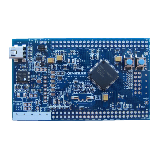
Target Board for RX130 2. Board Layout 2. Board Layout Figure 2-1 shows the external appearance of the top side of Target Board for RX130. MCU Header External Power Supply Header Evaluation Connector Reset Switch Power Indicator LED User Switch Current Consumption Measurement... -
Page 10: Parts Layout
Target Board for RX130 3. Parts Layout 3. Parts Layout Figure 3-1 shows the parts layout of Target Board for RX130. 2.54mm 2.54mm 5.08mm 90mm Figure 3-1: Parts Layout R20UT4169EJ0100 Rev.1.00 Page 10 of 24 Oct 13, 2017... -
Page 11: Operating Environment
Figure 4-1 shows the operating environment of the Target Board for RX130. Install the integrated development environment (IDE) from the following URL on the host PC. All the other required drivers are will be automatically installed with the IDE. https://www.renesas.com/rxtb USB Cable Targrt Board for RX130... -
Page 12: User Circuit
Target Board for RX130 5. User Circuit 5. User Circuit Evaluation MCU The MCU specification for the power supply, system clock, and reset at the time of shipment are as follows; Power supply: 3.3 V fixed (including analog power supply) System clock: Operated with on-chip oscillator Reset: Reset switch, IDE reset instruction USB Connector... -
Page 13: Pmod™ Connector
Target Board for RX130 5. User Circuit Pmod™ Connector The Pmod ™ connector (PMOD1) has a through hole at a pitch of 2.54 mm and is connected to the evaluation MCU according to Pmod™ Interface Type 2 A. Note that the Pmod ™ connector has the pin assignment different from other headers. -
Page 14: External Power Supply Header
Target Board for RX130 5. User Circuit External Power Supply Header When operating the evaluation MCU at an arbitrary voltage, or requiring current more than the USB current capacity, use the external power supply header (J4) for power supply. The available voltage depends on the evaluation MCU. -
Page 15: Current Consumption Measurement Header
Target Board for RX130 5. User Circuit Current Consumption Measurement Header The current consumption measurement header (JP2) is used for measuring current consumption of the evaluation MCU. The current consumption can be measured by connecting an ammeter to the evaluation MCU. -
Page 16: Emulator Reset Header
Target Board for RX130 5. User Circuit 5.13 Emulator Reset Header The emulator enters the forced reset state by short-circuiting the emulator reset header (EJ2). The evaluation MCU can be operated independently without controlling the IDE. Figure 5-7 shows the emulator reset header position. -
Page 17: Configuration
Target Board for RX130 6. Configuration Configuration Modifying the Target Board for RX130 This section describes how to change the Target Board for RX130 setting by using option link resistance. A option link resistor is a 0Ω surface mount resistor, which is used to short or isolate a part of circuits. See the 6.2 below for the list of option links by function. -
Page 18: Handling Precautions
Target Board for RX130 7. Handling Precautions Handling Precautions Board Thickness Please be extra careful when handling the Target Board for RX130 as the board is thin (0.8 mm). Additional Load When adding loads by USB power supply, the maximum operational current is 300 mA at 3.3 V, current is 100 mA at 5 V operation. -
Page 19: Code Development
Target Board for RX130 8. Code Development Code Development Figure 8-1 shows the setting of e2 studio when creating a new project for the Target Board for RX130. Debug hardware: Select [E2 Lite (RX)]. Power supply from the emulator: Select [No]. Figure 8-1: e2 studio settings (Note) Do not connect other emulators to your PC while connecting the Target Board for RX130. -
Page 20: Additional Information
Copyright This document may be, wholly or partially, subject to change without notice. All rights reserved. Duplication of this document, either in whole or part is prohibited without the written permission of Renesas Electronics Europe Limited. © 2017 Renesas Electronics Corporation. All rights reserved. - Page 21 REVISION HISTORY Target Board for RX130 User’s Manual Description Rev. Date Summary Page 1.00 Oct 13, 2017 First Edition issued...
- Page 22 Target Board for RX130 User’s Manual Oct 13, 2017 Publication Date: Rev. 1.00 Published by: Renesas Electronics Corporation...
- Page 24 RX130 Group R20UT4169EJ0100...
Need help?
Do you have a question about the RX130 Series and is the answer not in the manual?
Questions and answers