Sign In
Upload
Manuals
Brands
R&S Manuals
Control Unit
OSP
R&S OSP Manuals
Manuals and User Guides for R&S OSP. We have
1
R&S OSP manual available for free PDF download: Operating Manual
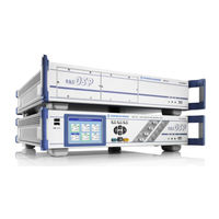
R&S OSP Operating Manual (234 pages)
Open Switch and Control Unit
Brand:
R&S
| Category:
Control Unit
| Size: 6.34 MB
Table of Contents
Basic Safety Instructions
3
Table of Contents
18
1 Documentation Overview
26
Front Panel Tour R&S OSP120
28
2 Preparing for Use
28
Front Panel Connectors
29
Status Leds and Standby Key
29
Front Panel Tour R&S OSP1
30
Navigation Keys
31
Status Keys
31
Status Indicators
31
Front Panel USB Connectors
32
Front Panel Tour R&S OSP150
32
Rear Panel Tour
32
LAN Connector
33
CAN Bus Connector
34
Mains Switch and Connector
34
Putting the Instrument into Operation
35
Unpacking the Instrument and Checking the Shipment
35
Instrument Setup
36
Bench Top Operation
36
Mounting in a 19" Rack
36
EMI Protective Measures
36
Connecting the Instrument to the AC Supply
37
Power on and off
37
Replacing Fuses
37
Standby and Ready State
38
Maintenance
38
Storing and Packing
39
Connecting External Accessories
39
Connecting a USB Flash Drive
39
Connecting a Keyboard
39
Connecting a Monitor
40
Connecting a LAN Cable
40
Starting the R&S OSP and Shutting down
41
Remote Operation in a LAN
41
Assigning an IP Address
41
R&S OSP Panel
44
Linux Operating System
44
Keyboard Properties
45
Firmware Update
45
Read the Actual the Firmware Version
47
Get Firmware Version Using R&S OSP Panel
47
Get Firmware Version Via SCPI Command
48
Figure 3-1: Manual Operation of R&S OSP120 Using GUI
49
Figure 3-2: Manual Operation of R&S OSP130 Using the GUI
49
Connecting R&S OSP and PC
50
Figure 3-3: Operation of R&S OSP120/130 by OSP Panel Software or Web-GUI
50
Installing the R&S OSP Panel
51
R&S OSP Panel Functions
51
Configuring/Connecting R&S OSP Panel
52
Addressing R&S OSP Device
54
Changing the IP Address with R&S OSP Panel
56
General Actions of R&S OSP Panel
57
Addressing R&S OSP Modules
58
Controlling the R&S OSP-B101/-B106/-B107/-B111/-B127/-B132
59
Controlling the R&S OSP-B102/-B112/-B128
60
Controlling the R&S OSP-B103/-B158
62
Controlling the R&S OSP-B104/-B114
64
Figure 3-4: AU600 Panel Design
64
Controlling the R&S OSP-B108
68
Controlling the R&S OSP-B116/-B136
69
Controlling the R&S OSP-B131
69
Controlling the R&S OSP-B142
70
Getting Started
49
Save a Path
72
Delete a Path
74
Switch a Path
74
Export a Path
75
Import a Path
77
Path Configuration
71
Sample Session
78
Example Path Configuration
78
Manual Setting of the Paths
82
Remote Control Setting of the Path Configuration
83
Path Configuration in Virtual Mode
84
Simulated Module Configuration
84
Path Configuration
85
Import of Path Configuration
86
GUI Info Line
86
Configuring the GUI Info Line
87
Manual Operation
89
Manual Operation of the Modules
89
R&S OSP Setups
89
5 Instrument Functions
90
R&S OSP Instrument Frame
90
Figure 5-1: Block Diagram R&S OSP120
91
R&S OSP Block Diagram
91
Figure 5-2: Block Diagram R&S OSP130
92
Figure 5-3: Block Diagram R&S OSP150
92
Figure 5-4: R&S OSP Module Slots
93
Figure 5-5: R&S OSP120 Version12 Module Slots at Front Side
93
R&S OSP Module Slots
93
R&S OSP120 Version12 and Module Slots
93
Figure 5-6: Block Diagram R&S OSP120 Var. 12
94
R&S OSP120 Version12 and Modules R&S OSP-B011/-B012
94
Figure 5-7: Block Diagram R&S OSP120 Var. 12
95
Figure 5-8: R&S OSP-B011 Module Panel
95
Figure 5-9: R&S OSP-B011 Module Panel
96
R&S OSP150 Version15 and Module Slots
96
Figure 5-10: R&S OSP150 Version15 Module Slots at Front Side
97
Figure 5-11: Block Diagram R&S OSP150 Var. 15
97
R&S OSP150 Version15 and Modules R&S OSP-B011/-B012
98
Module Functions
98
RF Switch Module R&S OSP-B101/-B107/-B111/-B127
98
Figure 5-12: Module R&S OSP-B101
98
RF Switch Module R&S OSP-B102/-B112/-B128
99
Figure 5-13: Block Diagram Module R&S OSP-B101
99
Figure 5-14: Module R&S OSP-B102
100
Figure 5-15: Block Diagram Module R&S OSP-B102
100
I/O Module R&S OSP-B103
101
Figure 5-16: Module R&S OSP-B128
101
Figure 5-17: Module R&S OSP-B103
102
Figure 5-18: Block Diagram Module R&S OSP-B103
102
I/O Module R&S OSP-B104
103
Figure 5-19: Module R&S OSP-B104
103
Figure 5-20: Block Diagram Module R&S OSP-B104
104
RF Switch Module R&S OSP-B106/-B132
105
Figure 5-21: Module R&S OSP-B106
105
DC MUX Module R&S OSP-B108
106
Figure 5-22: Block Diagram Module R&S OSP-B106
106
Figure 5-23: Module R&S OSP-B108
106
RF Switch Module R&S OSP-B121 and R&S OSP-B121H
107
Figure 5-24: Module R&S OSP-B121
107
Figure 5-25: Block Diagram Module R&S OSP-B121
107
RF Switch Module R&S OSP-B122
108
Figure 5-26: Module R&S OSP-B122
108
RF Switch Module R&S OSP-B123 and R&S OSP-B124
109
Figure 5-27: Block Diagram Module R&S OSP-B122
109
Figure 5-28: Module R&S OSP-B123
110
Figure 5-29: Module R&S OSP-B124
110
Figure 5-30: Block Diagram Module R&S OSP-B123
111
Figure 5-31: Block Diagram Module R&S OSP-B124
111
RF Switch Module R&S OSP-B125 and R&S OSP-B126
112
Figure 5-32: Module R&S OSP-B125
112
Figure 5-33: Module R&S OSP-B126
113
Figure 5-34: Block Diagram Module R&S OSP-B125
113
Module R&S OSP-B114 for EMS Application
114
Figure 5-35: Block Diagram Module R&S OSP-B126
114
Figure 5-36: Module R&S OSP-B114
115
Figure 5-37: Block Diagram Module R&S OSP-B114
115
RF Switch Module R&S OSP-B131
116
Figure 5-38: Module R&S OSP-B131
116
Figure 5-39: Block Diagram Module R&S OSP-B131
116
RF Switch Module R&S OSP-B129 and R&S OSP-B119
117
Figure 5-40: Module R&S OSP-B119 and R&S OSP-B129
117
Power Sensor Module R&S OSP-PM-I
118
Figure 5-41: Block Diagram Module R&S OSP-B129
118
RF Switch Module R&S OSP-B116 and R&S OSP-B136
119
Figure 5-42: Module R&S OSP-PM-I
119
Figure 5-43: Block Diagram Module R&S OSP-PM-I
119
RF Switch Module R&S OSP-B101L and R&S OSP-B102L
120
Figure 5-46: Module R&S OSP-B101L and R&S OSP-B102L
121
I/O and Supply Module R&S OSP-B158
122
RF Switch Module R&S OSP-B142
123
Graphical User Interface
124
Starting the R&S OSP120
124
Starting the R&S OSP130
127
General Navigation Operations
128
Using the R&S OSP-B101/-B106/-B107/-B111
131
Using the R&S OSP-B102/-B112
132
Using the R&S OSP-B103
133
Using the R&S OSP-B104
134
Using the R&S OSP-B121
136
Using the R&S OSP-B122
136
Using the R&S OSP-B123 to R&S OSP-B126 and R&S OSP-B129
137
Path Configuration
138
R&S OSP Switch Cycle Counter
142
R&S OSP Selftest
144
Selftest Via R&S OSP Panel
144
R&S OSP Configuration Check
144
System Info Via R&S OSP Panel
144
SCPI Read/Write
145
R&S OSP Temperature Read Command
146
Remote Control
148
Remote Control Operation
148
Establishing and Testing a LAN Connection
149
Switchover to Remote Control
150
Return to Manual Operation
150
Messages
150
Interface Messages
150
Device Messages (Commands and Device Responses)
151
SCPI Command Structure and Syntax
151
The R&S OSP Command Processing
155
Input Unit
155
Command Recognition
156
Data Base and Instrument Hardware
156
Status Reporting System
156
Output Unit
157
Status Reporting System
157
Overview of Status Registers
158
Contents of the Status Registers
158
Application of the Status Reporting System
160
Reset Values of the Status Reporting System
162
Remote Command Reference
163
Special Terms and Notation
163
Naming Conventions
164
Common Commands
166
Instrument-Control Commands
168
Route Commands
168
READ Commands
173
CONFIGURE Commands
177
Mmemory Commands
178
Diagnostic Commands
180
System Commands
181
Alphabetical List of Commands (System)
187
8 Applications
188
Configuration of the R&S EMC32 for R&S OSP
188
R&S OSP and R&S EMC32 Software
188
Defining the R&S OSP Properties in the R&S EMC32
190
Interlock Functionality with R&S EMC32
191
Setting the R&S OSP with the R&S EMC32
191
R&S OSP Drivers
194
Extending the R&S OSP System
195
R&S OSP150 Extension Unit
195
Connecting the R&S OSP150
196
How to Register the R&S OSP150
197
Application of Module R&S OSP-B103
198
Controlling External Relays with R&S OSP-B103
198
Input Ports of R&S OSP-B103
201
Output Ports of R&S OSP-B103
202
Application of Module R&S OSP-B104
202
Controlling External Power Relays with R&S OSP-B104
202
Interlock Monitoring with the R&S OSP-B104
203
Input Ports of R&S OSP-B104
204
Output Ports of R&S OSP-B104
205
Application of Module R&S OSP-B114
205
Switching a Signal Generator Via the R&S OSP-B114 Module
206
Interlock Circuitry with the R&S OSP-B114 Module
207
I/O Ports on the R&S OSP-B114 Module
208
Application of Module R&S OSP-B158
209
Controlling Active Antennas with R&S OSP-B158
209
Appendix
210
Interfaces and Connectors
210
Front Panel Connectors
210
Rear Panel Connectors
210
Figure 9-1: Pin Assignment CAN Bus Connector
211
LAN Interface
212
Figure 9-3: VXI–11 Channels between Instrument and Controller
213
R&S OSP Module Interfaces
214
R&S OSP-B101/-B107/-B111/-B127 Interface
214
R&S OSP-B102/-B112 Interface
215
R&S OSP-B103 Interface
215
R&S OSP-B104 Interface
216
Figure 9-9: Pin Assignment R&S OSP-B104 Relay Control
217
R&S OSP-B108 Interface
218
R&S OSP-B106 Interface
219
R&S OSP-B121 Interface
219
R&S OSP-B122 Interface
220
R&S OSP-B123 Interface
220
R&S OSP-B124 Interface
221
R&S OSP-B125 Interface
222
R&S OSP-B126 Interface
222
R&S OSP-B114 Interface
222
Figure 9-20: Layout the Connectors of R&S OSP-B114
223
R&S OSP-B128 Interface
224
R&S OSP-B131 Interface
225
R&S OSP-B132 Interface
225
R&S OSP-B101L Interface
226
R&S OSP-B129/-B119 Interface
226
R&S OSP-B142 Interface
227
R&S OSP-PM-I Interface
228
R&S OSP-B116/-B136 Interface
229
R&S OSP-B158 Interface
229
Figure 9-31: Pin Assignment R&S OSP-B158 SUPPLY
230
Index
232
Advertisement
Advertisement
Related Products
R&S OSP Series
R&S OSP220
R&S OSP320
R&S OSP-B200S2
R&S OSP230
R&S 1169.3206.02
R&S 1169.4102.02
R&S NRP-Z27
R&S NRP-Z37
R&S SMCVB-K167
R&S Categories
Measuring Instruments
Test Equipment
Portable Generator
Power Supply
Accessories
More R&S Manuals
Login
Sign In
OR
Sign in with Facebook
Sign in with Google
Upload manual
Upload from disk
Upload from URL