Sign In
Upload
Manuals
Brands
Omron Manuals
Machine Vision Systems
SYSMAC FH-L Series
Omron SYSMAC FH-L Series Vision System Manuals
Manuals and User Guides for Omron SYSMAC FH-L Series Vision System. We have
3
Omron SYSMAC FH-L Series Vision System manuals available for free PDF download: User Manual, Hardware Setup Manual
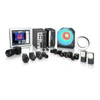
Omron SYSMAC FH-L Series User Manual (582 pages)
Vision Sensor
Brand:
Omron
| Category:
Machine Vision Systems
| Size: 26 MB
Table of Contents
Fh-1£££/Fh
3
Intended Audience
3
Applicable Products
3
Relevant Manuals
4
Manual Structure
6
Page Structure
6
Special Information
7
Z365-E1
8
Table of Contents
9
Terms and Conditions Agreement
17
Warranty, Limitations of Liability
17
Application Considerations
18
Disclaimers
18
Safety Precautions
20
Symbols and the Meanings for Safety Precautions Described in this Manual
20
Meanings of Alert Symbols
20
Warning
21
Precautions for Safe Use
22
Condition of the Fitness of OMRON Products
22
Installation Environment (FH Series)
22
Installation Environment (FHV Series)
23
Power Supply and Wiring (FH Series)
23
Power Supply and Wiring (FHV Series)
23
Grounding (FH Series)
24
Mounting (FHV Series)
25
Others (FH Series)
25
Others (FHV Series)
26
Precautions for Correct Use
27
Installation and Storage Sites (FH-1000/2000/3000/5000 Series)
27
Installation and Storage Sites (FH-L Series)
27
Installation and Storage Sites (FHV Series)
27
Orientation of Product
28
Ambient Temperature
28
Noise Resistance
28
Component Installation and Handling (FH Series)
28
Component Installation and Handling (FHV Series)
29
Maintenance (FH Series)
29
Maintenance (FHV Series)
29
Communications with Upper Device
30
Failsafe Measures
30
Connecting the Sensor Controller and Monitor with a Switcher and Splitter (FH Series)
30
Warm-Up (FHV Series)
30
Camera Installation (FHV Series)
30
Beam (FHV Series)
31
Others (FHV Series)
31
LED Safety (FHV Series)
31
Regulations and Standards
33
All Series
33
FH-1000/2000/3000/5000 Series
33
FH-L Series
34
FHV Series
35
Related Manuals
36
Terminology
39
Revision History
44
Sections in this Manual
45
Section 1 Overview
48
Checking the System Configuration
48
System Configuration
48
Functional Comparison between the FH-Series and FHV-Series Controllers
49
Functional Comparison between the FH-Series and FHV-Series Con- Trollers
49
Flow of Application
52
Features
55
Section 2 Features
56
Basic Mechanism for Measurements
56
Support for a Variety of Scenes and Measurement Lines
58
Basic Operations
61
Section 3 Basic Operations
62
Preparing the Controller and Cameras
62
Camera Setup
62
Preparing the Controller
64
Adjusting the Camera
64
Basic Knowledge about Operations
66
Inputting Values
66
Inputting Text
66
Selecting Files and Folders
69
Available Operations in Select File Window
71
Using the Zoom Function
73
Setting Figures
73
Changing the Image Mode and Other Display Contents
81
Changing the Display Ratio
82
Checking System Information [System Information]
84
Checking the Memory Consumption and Percentage of Memory Used
88
Capturing Screen Images
89
Setting the Destination for Captured Images
89
Saving Captured Images
89
Saving Settings before Turning off the Power and Restarting
91
Saving the Setting to the Controller [Data Save]
91
Device Information Storage Tool
91
Restarting the Controller [System Restart]
93
Initializing the Controller [System Initialization]
96
Initializing with Sensor Controller
96
Initializing with Remote Operation
96
Updating Measurement Application [Version-Up]
98
By the Sensor Controller (FH Series)
98
By the Sensor Controller (FHV Series)
103
By the Remote Operation
105
Section 4 Setting the Controller
110
Setting the Controller
110
Selecting Language [Startup Settings]
110
Setting the Status at Startup [Startup Settings]
111
Setting Communication [Startup Settings]
114
Setting Operation Mode [Startup Settings]
119
Setting the Operation Mode
119
Parallel Processing
135
Checking the Camera Connections [Camera Connection]
146
Setting the Trigger Delay [Inter-Camera Setting]
147
Trigger Delay Setting
147
Setting the SHTOUT Signal [Output Signal Settings]
150
Setting the Conditions Related to Communications
153
Setting Date/Time [Date/Time Settings]
154
Setting Fan Control [Fan Control Setting]
156
Setting the Pulse Width for the STEP Input Detection [STEP Signal Filter Setting]
157
Setting the Pulse Width for the STEP Input Detection [STEP Sig- Nal Filter Setting]
157
Setting Encoder Trigger [Encoder Trigger Setting]
158
Setting Network Drive [Network Drive Setting]
160
Setting Screen Capture [Screen Capture Setting]
163
Setting the Conditions that Are Related to Operation During Measurement [Measurement Conditions]
164
Setting Logging Conditions [Logging Setting]
166
Setting Operation Log [Operation Log Setting]
167
Setting the Operation at Error [Error Setting]
168
Setting Character Code Using Macro/Variable Function [Macro/Variable Function Setting]
170
Changing Display Settings for Screen Keyboard [Screen Keyboard Settings]
171
Changing Display Settings for Screen Keyboard [Screen Key- Board Settings]
171
Creating Measurement Scenes
173
Section 5 Creating Measurement Scenes
174
What Is a Scene
174
Example of a Scene
175
Creating a Scene
177
Editing Processing Units in Scenes
179
Displaying and Checking Processing Branches in a Scene
182
Overview [Flow Viewer]
182
Window Configuration [Flow Viewer]
182
Flow Editing Functions [Flow Viewer]
183
Examples of Branch and Folder Views [Flow Viewer]
185
Using Variables to Edit the Flow [TDM Editor]
186
Edit Flow Screen
186
Editing Processing Units in a Scene [TDM Editor]
196
Editing Scenes [TDM Editor]
205
Using Variables
215
Performing Measurement and Adjustment
241
Section 6 Performing Measurement and Adjustment
242
Executing Test Measurements
242
Key Points for Adjustment
244
Stabilizing Measurements
244
Shortening Processing Time
245
Useful Functions for Operation
247
Logging Measurement Values and Measurement Images [Data Logging/Image Logging]
247
Logging Measurement Values and Measurement Images [Data Log- Ging/Image Logging]
247
Saving Data to an External Device [Ftp/Network Drive]
260
Remeasuring Saved Images [Remeasurement]
263
Improving Adjustment Efficiency [Judgement Result Monitor]
264
Analyzing Inspection and Measurement Results [NG Analyzer]
266
Layout of NG Analyzer Window
266
Using Method of NG Analyzer
268
Saving Measurement Values
270
Changing Judgement Conditions Without Stopping Measurement [Simplified Non-Stop Adjustment]
271
Changing Regions as a Batch [Shift Area]
272
Updating the Reference Position Data for a Unit in the Measurement Flow [Update Standard Position Tool]
274
Monitoring Measurement Value Trends [Trend Monitor]
275
Clearing Measurement Results [Clear Measurement]
276
Clearing Saved Images [Clear Logging Image]
276
Managing Images Used for Model Registration and Reference [Registered IM- Age Manager]
278
Managing Images Used for Model Registration and Reference [Registered Image Manager]
278
Specifying the Destination to Save
278
Registering Images
280
Renaming Image Names
281
Deleting Images
281
Loading Images
282
Verifying Calibration Results [Calibration Support Tool]
283
Checking the Calibration Results
283
Data Setting
283
Increasing/Switching Measurement Scenes
285
Section 7 Increasing/Switching Measurement Scenes
286
What Is a Scene Group
286
Switching the Scene or Scene Group
287
Switching the Scene
287
Switching Scene Groups
287
Editing Scenes [Scene Maintenance]
290
Copying Scenes
290
Deleting Scenes
290
Renaming a Scene and Adding a Description
291
Editing Scene Groups [Scene Maintenance]
292
Copying Scene Groups
292
Deleting Scene Groups
292
Renaming the Scene Group Name
293
Saving Scene Groups in External Storage [Scene Group Saving Destination Settings]
295
Increasing the Number of Scenes in a Group to more than 128 Scenes [Con- Version Scene Group Data Tool]
298
Increasing the Number of Scenes in a Group to more than 128 Scenes [Conversion Scene Group Data Tool]
298
Overview
298
Operating Procedure for the Conversion Scene Group Data Tool
298
Section 8 Setting Windows
303
Setting Windows
303
Windows
303
Types of Windows
303
Overview of Window Navigation
303
Main Window (Layout 0): Adjustment Window (Default)
304
Main Window (Layout 1): Run Window (Default)
308
Adjustment Windows and Run Windows
309
Main Window (Layout 0): Adjustment Window (Default)
309
Main Window (Layout 1): Run Window (Default)
310
Main Window (Layout 1): Switching to the Run Window
310
Main Window (Layout 1): Switching to the Adjustment Window
310
Arranging Windows [Layout Functions]
312
Arranging Window Elements [Layout Modification]
312
Setting the Behavior of Output Signals for each Layout [Layout Setup]
322
Switching Layout Numbers in the Main Window [Switch Layout]
324
Judgement Pane
324
Information Pane
324
Toolbox Pane
325
Measurement Pane
327
Flow Display Pane
327
Detail Result Pane
328
Image Container Pane
329
Error Pane
333
Image File Display Pane
334
Label Pane
336
Extended Window Parts
337
Data Grid Window (Mdi_Datagrid.dll)
338
Login Account Display Window (Mdi_Disploginuser.dll)
344
Setting Dialog Box Display Button Window (Mdi_Dispsetupbtn.dll)
345
Text Display Window (Mdi_Disptext.dll)
347
Custom Dialog Display Button Window (Mdi_Executebtn.dll)
349
Macro Trigger Window (Mdi_Mcrtrigger.dll)
352
Message Box Display Window (Mdi_Msgbox. Dll)
353
Value Input Window (Mdi_Numbox.dll)
354
Data Settings Button Window (Mdi_Setdatabtn.dll)
355
Simple Data Grid Window (Mdi_Simpledatagrid.dll)
358
Troubleshooting
363
Editing Contents Are Not Reflected When You Confirm the Sensor Controller Af- Ter Edit a Layout by Remote Control [Custom Dialog Tool]
364
Flow of Use
364
Custom Dialog Tool
364
Launching Your Custom Dialog Box
383
Saving/Loading Data
385
Section 9 Saving/Loading Data
387
Saving Data to the FH Series/Fhv Series
387
About Saving Areas
387
External Drive Names
389
Using External Storage Devices
389
Shared Folder on a Computer Connected to the Network
390
Saving Settings Data to the Flash Memory
391
Saving Setting Data to the Controller Ramdisk or an External Storage Device
392
Saving Logged Images in the Controller Memory (RAM) to a Ramdisk or an Ex- Ternal Storage Device
394
Saving Logged Images in the Controller Memory (RAM) to a Ramdisk or an External Storage Device
394
Copying or Moving Files between the Controller Ramdisk and an External Storage Device
396
Loading Settings Data from the Controller Ramdisk or an External Storage De- Vice to the Sensor Controller
397
Loading Settings Data from the Controller Ramdisk or an Exter- Nal Storage Device to the Sensor Controller
397
Backing up Sensor Controller Setting Data [Configuration Copy]
399
Before Backing up
399
Backing up Sensor Controller Settings
401
Restoring Saved Settings
411
Troubleshooting
414
Copying Settings for each Line in Multi-Line Random-Trigger Mode [Line Maintenance]
416
Before Use of Line Maintenance
416
Line Maintenance Tool Operations
420
Operating with Functional Limitations
425
Troubleshooting
429
Saving Image Files to a Ramdisk or an External Storage Device [Image File Save]
430
Saving Logging Images
430
Saving Image Files
431
Outputting a List of Scene Data Setting Values [Setting Values Download/Upload Tools]
433
Downloading Setting Values
433
About Downloaded CSV Files
434
Uploading Setting Values
435
Saving/Loading Layout Settings [Layout Upload, Download Tool]
437
Advanced Usage
439
Remotely Operating the Controller [Remote Operation]
441
Environment Settings
442
Connection Method for Remote Operation
447
Terminating Remote Operation
450
Differences from Local Operation and Limitations
451
Multi-Trigger Imaging Processing with any Timing [Multi-Trigger Imaging]
453
Settings for Multi-Trigger Imaging
453
Restrictions
455
Setting Methods
456
About Multi-Input Function (Multi-Trigger Imaging)
460
Troubleshooting
466
Limiting User Operations [Security Settings]
467
Setting Accounts (Account List)
467
Setting Layout Restrictions
471
Setting User Group Operation Restrictions
472
Saving/Loading/Deleting the Security Settings
474
Recording the Operation History [Operation Log]
480
Using the Operation Log
480
Operation Log Format
483
Setting the Keyboard Layout for the Controller [Keyboard Layout Selection Tool]
484
10-6 Switching User Accounts
486
Logging in
486
Logging out
487
Customizing Communication Commands [Communication Command Macro]
488
Customizing Communication Commands [Communication Com- Mand Macro]
488
Extending the Functions in a Measurement Flow or Scene [Scene Control Mac- Ro Tool]
489
Extending the Functions in a Measurement Flow or Scene [Scene Control Macro Tool]
489
Positioning Workpieces for Stage and Robot Applications [Alignment Function]
490
Positioning Workpieces for Stage and Robot Applications [Align- Ment Function]
490
Overview
490
Execution of Calibration
492
Troubleshooting
498
Alignment
499
Alignment Processing Items
505
What to Do
507
11-1 Error Messages and Troubleshooting
508
11-2 Faq
515
During Start-Up
515
During Operation
516
For Measurement
517
About Parallel Interface
518
Serial Interface (RS-232C/422 Connection)
519
Camera with Lighting Controller
520
Appendices
521
A-1 Menu List
523
A-2 External Tool List
526
A-3 FHV Series Tools
527
A-4 FHV Series Processing Items
528
A-4-1 Measurement
528
A-4-2 Input Image
528
Measurement
528
Input Image
528
A-4-3 Compensate Image
529
A-4-4 Support Measurement
529
A-4-5 Branch
529
A-4-6 Output Result
530
A-4-7 Display Result
530
A-5 Measurement Mechanism
531
A-5-1 Color Processing Mechanism
531
Color Processing Mechanism
531
A-5-2 Search Processing Mechanism
532
Edge Detection Measurement
535
A-5-4 Defect Detection Measurement
538
A-5-5 Handling Coordinates
539
A-6 Image File
541
A-6-1 IFZ File Type
541
A-6-2 BMP(BFZ) File Type
541
A-6-3 JPG(JFZ) File Type
541
A-6-4 Differences Among IFZ/BMP(BFZ)/JFZ(JFZ) File Types
542
IFZ File Type
542
BMP(BFZ) File Type
543
A-7 about Number of Logging Images
544
A-7-1 Calculation Method
544
Calculation Method
544
A-7-2 Color Camera
545
A-7-3 Monochrome Camera
545
A-7-4 FHV Series
546
About Max. Number of Loading Images During Multi-Input
547
A-8-1 FH Series
547
A-8-2 FHV Series
547
FH Series
547
About Memories Usable with FH Series/Fhv Series
549
Memory Usage Guidance for Processing Items
550
A-11 Memory Display Image on PLC I/O
556
Sharing Data Within the Controller [User Data Tool]
557
A-12-1 Setting Procedure for User Data
557
A-13 Operation Log Input Information List
559
A-14 Character Code Table
570
Advertisement
Omron SYSMAC FH-L Series User Manual (647 pages)
for Communication Settings
Brand:
Omron
| Category:
Machine Vision Systems
| Size: 14 MB
Table of Contents
Fh-3£££/Fh
3
Intended Audience
3
Applicable Products
3
Relevant Manuals
4
Manual Structure
6
Page Structure
6
Special Information
7
Conventions Used in this Manual
7
Table of Contents
9
Z342-E1
12
Terms and Conditions Agreement
13
Safety Precautions
15
Precautions for Safe Use
16
Precautions for Correct Use
17
Regulations and Standards
18
Related Manuals
19
Revision History
21
Sections in this Manual
23
Overview
25
Introduction
26
Confirming the System Configuration
27
System Configuration
27
Communicating with an External Device
28
Basic Control Operations of the Sensor Controller
28
Communications between the Sensor Controller and an External Device
29
Control Methods for the Sensor Controller
31
Communication Protocols for Communicating with the Sensor Controller
33
Saving Sensor Controller Data to an External Device
35
Control Methods Using an External Device
37
Control with Control Signals and Status Signals
37
Command/Response Method
40
Data Output after Measurements
41
Setting Procedures for Communications
52
Communications Setup Procedures
52
Communications Protocols and Communications Modules
53
Differences in Specifications Based on the Communications Protocol
55
Differences in Specifications Based on the Communications Pro- Tocol
55
List of Supported Signals by Communications Protocol
55
Restrictions When Using Different Communication Protocols Simultaneously
57
Restrictions When Using Different Communication Protocols Simulta- Neously
57
Restrictions in Communication Protocols by Operation Mode
57
Models Being Compatible with Communication Protocol
58
Ethercat Connections
66
Introduction to Ethercat
66
Structure of CAN Application Protocol over Ethercat (Coe)
69
Ethercat Slave Information Files (ESI Files)
70
Transitions of Communications States
71
Process Data Objects (Pdos)
72
Service Data Objects (Sdos)
75
Communications between Master and Slaves for Ethercat
76
Communication Method of FH Sensor Controller Connected by Ethercat
77
Communications Settings
82
Communications Module Settings (Startup Settings)
84
Communication Specifications Settings
85
Output Data Settings (Processing Item Registration)
90
Setting Output Data (Numerical Values/Character Strings)
93
Ethercat Network Configuration Settings
100
Communication Test
101
I/O Ports by Area (PDO Mapping) and Memory Allocation
102
I/O Signals
108
Measurement Results for Which Output Is Possible (Fieldbus Data Output)
112
Command List
114
Measurement Trigger Input
117
Command Response Processing
118
Data Output
120
Timing Chart
123
Ethercat Troubleshooting
127
Sysmac Error Status
129
Sysmac Device Features
147
Object Dictionary
150
Communicating by PLC Link
189
Communications Processing Flow
189
Communications Settings
191
Communications Module Settings (Startup Settings)
192
Communication Specifications Settings
194
Output Data Settings (Processing Item Registration)
215
Setting Output Data (Numerical Values and Character Strings)
220
Testing Communications
227
Memory Allocation
231
I/O Signals
235
Output Items
238
Command List
239
Command Response Processing
243
Data Output
246
Timing Chart
248
PLC Link Troubleshooting
251
Communicating by Ethernet/Ip
254
Introduction to Ethernet/Ip
254
Data Exchange with Ethernet/Ip
255
Ethernet/Ip Communications
258
Communications Processing Flow
259
Communications Settings
261
Communications Module Settings (Startup Settings)
262
Communication Specifications Settings
263
Setting Tag Data Link
270
Output Data Settings (Processing Item Registration)
275
Setting Output Data (Numerical Values and Character Strings)
280
Testing Communications
287
Memory Allocation
289
I/O Signals
299
Output Items
303
Command List
304
Command Response Processing
308
Data Output
312
Timing Chart
314
Communicating with the Sensor Controller Using Ethernet/Ip Message Communications
317
Communicating with the Sensor Controller Using Ethernet/Ip Mes- Sage Communications
317
Example for Command Settings
320
Ethernet/Ip Troubleshooting
321
Communicating by PROFINET
324
Overview of PROFINET
324
PROFINET Communications
327
Communications Processing Flow
328
Communications Settings
330
Communications Module Settings (Startup Settings)
331
Communication Specifications Settings
332
IO Data Communication Settings
338
Output Data Settings (Processing Item Registration)
340
Setting Output Data (Numerical Values and Character Strings)
344
Testing Communications
351
Memory Allocation
354
I/O Signals
360
Output Items
364
Command List
365
Command Response Processing
368
Data Output
371
Timing Chart
373
PROFINET Troubleshooting
376
Non-Procedure Communications
378
Communications Processing Flow
378
Communications Setup Procedures
379
Communications Module Settings (Startup Settings)
379
Communications Specifications Settings
381
Output Data Settings (Processing Item Registration)
386
Output Data Settings (Numerical Values/Character Strings)
392
Testing Communications
400
Output Items
403
Command Formats
405
Command List
407
Output Format
411
Non-Procedure Communications Troubleshooting
413
Parallel Communications
416
Communications Processing Flow
416
Communications Setup Procedures
418
Communications Module Settings (Startup Settings)
419
Communications Specifications Settings
425
Output Data Settings (Processing Item Registration)
428
Output Data Settings (Numerical Value/Judgment)
434
Testing Communications
440
I/O Signals
442
Output Items
453
Command Formats
455
Time Charts
459
Parallel Troubleshooting
472
Appendices
473
A-1 Command Control
474
A-1-1 Parameter Notation Examples for Command Control
474
Parameter Notation Examples for Command Control
474
A-1-2 Details of Commands Used in Ethercat Communications
478
A-1-3 Command List
479
Command List
479
A-1-4 Command Details for PLC Link, Ethernet/Ip, Ethercat, and PROFINET
487
A-1-5 Non-Procedure Command Details
556
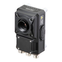
Omron SYSMAC FH-L Series Hardware Setup Manual (244 pages)
Vision System
Brand:
Omron
| Category:
Accessories
| Size: 14 MB
Table of Contents
Intended Audience
3
Applicable Products
3
Relevant Manuals
4
Manual Structure
6
Page Structure
6
Special Information
7
Table of Contents
9
Terms and Conditions Agreement
13
Warranty, Limitations of Liability
13
Application Considerations
14
Disclaimers
14
Safety Precautions
16
Symbols and the Meanings for Safety Precautions Described in this Manual
16
Meanings of Alert Symbols
16
Warning
17
Precautions for Safe Use
18
Condition of the Fitness of OMRON Products
18
Installation Environment
18
Power Supply and Wiring
19
Grounding
19
Others
19
Precautions for Correct Use
21
Installation and Storage Sites (FH-1000/2000/3000/5000 Series)
21
Installation and Storage Sites (FH-L Series)
21
Orientation of Product
21
Ambient Temperature
21
Noise Resistance
22
Component Installation and Handling
22
Maintenance
22
Communications with Upper Device
22
Failsafe Measures
23
Connecting the Sensor Controller and Monitor with a Switcher and Splitter
23
Regulations and Standards
24
All Series
24
FH-1000/2000/3000/5000 Series
24
FH-L Series
25
Related Manuals
27
Terminology
28
Sensor Controller
28
Revision History
33
Sections in this Manual
35
Sensor Controller
38
FH-2£££/FH-3£££/FH-5£££ Series
38
10/FH-2£££-10/FH-3£££-10/FH-5£££-10 Series
38
FH-1£££-20/FH-2£££-20/FH-3£££-20/FH-5£££-20 Series
39
FH-L£££ Series
39
FH-L£££-10 Series
39
Sold Separately
41
Cameras and Related
41
Monitor
43
Lighting and Lighting Controller
44
Accessories
45
Cable
46
Software
48
Overview of System
52
Basic System of Measurement
52
FH-1000/FH-2000/FH-3000/FH-5000 Series
54
FH-L Series
55
System Configuration
56
FH-1000/2000/3000/5000 Series
56
FH-L Series
57
Flow of Use Procedure
58
Configuration
61
Sensor Controller
63
FH-1000/2000/3000/5000 Series
63
FH-L Series
74
Camera
79
High-Speed Digital CMOS Camera (FH-S Camera Series)
79
Digital CMOS Camera
84
Digital CCD Camera: FZ-S Camera Series
87
High-Speed Digital CCD Camera: FZ-SH Camera Series
89
Small Digital CCD Cameras: FZ-S Camera Series
90
Intelligent Compact Digital CMOS Camera: FZ-S Camera Series
93
Camera Cable
96
Camera Cable and Right-Angle Camera Cable
96
Bend Resistant Camera Cable and Bend Resistant Right-Angle Camera Cable
97
Bend Resistant Camera Cable and Bend Resistant Right-Angle Cam- Era Cable
97
Long-Distance Camera Cable and Long-Distance Right-Angle Camera Cable
98
Long-Distance Camera Cable and Long-Distance Right-Angle Cam- Era Cable
98
Cable Connection Table
99
Cable Extension Units
103
Lens
107
C-Mount Lens for 1/3-Inch Image Sensor (SV-V Series)
107
C-Mount Lens for 2/3-Inch Image Sensor (SV-H Series)
108
C-Mount Lens for 1-Inch Image Sensor (VS-H1 Series)
109
C-Mount Lens for 4/3-Inch Image Sensor (VS-LLD Series)
110
M42-Mount Lens for Large Image Sensor (VS-L/M42-10 Series)
111
Lenses for Small Camera (FZ-LES Series)
111
Vibration and Shock Resistant C-Mount Lens for 2/3-Inch Image Sensor (VS-MCA Series)
112
Vibration and Shock Resistant C-Mount Lens for 1-Inch Image Sensor (VS-MCH Series)
114
Vibration and Shock Resistant C-Mount Lens for 1-Inch Image Sen- Sor (VS-MCH Series)
114
Vibration and Shock Resistant C-Mount Lens for 1-Inch Image Sensor (VS-MCH1 Series)
117
Vibration and Shock Resistant C-Mount Lens for 1-Inch Image Sen- Sor (VS-MCH1 Series)
117
Vibration and Shock Resistant M42-Mount Lens for 1.8-Inch Image Sensor (VS-MCL/ M42-10 Series)
120
Vibration and Shock Resistant M42-Mount Lens for 1.8-Inch Image Sensor (VS-MCL/M42-10 Series)
120
High-Resolution Telecentric Lens for C-Mount Lens for 2/3-Inch Image Sensor (VS-TCH Series)
122
High-Resolution Telecentric Lens for C-Mount Lens for 1.1-Inch Image Sensor (VS-TEV Series)
124
High-Resolution Telecentric Lens for C-Mount Lens for 1.1-Inch IM- Age Sensor (VS-TEV Series)
124
Extension Tubes
125
Meaning of Optical Chart
126
Touch Panel Monitor and Cable
142
LCD and Cable
148
Sysmac Studio
151
Handling and Installation Environment
153
All Series
154
FH-1000/2000/3000 Series
156
FH-L Series
157
Setup and Wiring
159
When Turning on and off
160
All Series
160
FH-1000/2000/3000/5000 Series
161
FH-L Series
161
Fail-Safe Measures
162
Sensor Controller Installation
163
All Series
163
FH-1000/2000/3000/5000 Series
163
FH-L Series
169
Setup Touch Panel Monitor or Monitor
178
All Series
178
FH-1000/2000/3000/5000 Series
178
FH-L Series
178
Camera Installation
180
All Series
180
FH-1000/2000/3000/5000 Series
181
FH-L Series
182
Insert/Remove SD Memory Card or USB Memory
183
Common in All Series
183
Use by Connecting Software
184
Sysmac Studio FH Tool
184
FZ_FH Remote Operation Tool
184
Simulation Software
184
Installation in a Control Panel
185
All Series
185
FH-1000/2000/3000/5000 Series
187
FH-L Series
189
I/O Interface
197
Parallel Interface
198
All Series
198
FH-1000/2000/3000/5000 Series
199
FH-L Series
208
Other (Parallel Converter Cable)
214
Encoder Interface
225
FH-1000/2000/3000/5000 Series
225
Ethercat Interface
228
FH-1000/2000/3000/5000 Series
228
Ethernet Interface
230
FH-1000/2000/3000/5000 Series
230
FH-L Series
232
Serial Interface
234
All Series
234
Advertisement
Advertisement
Related Products
Omron SYSMAC FH Series
Omron SYSMAC FHV Series
Omron STC-APB503PCL
Omron STC-APC503PCL
Omron STC-HD203 Series
Omron STC-HD203DV
Omron STC-HD203DV-CS
Omron STC-HD203SDI
Omron STC-HD203SDI-CS
Omron CoaXPress STC-MCS510CXP6
Omron Categories
Blood Pressure Monitor
Controller
Accessories
Switch
Inverter
More Omron Manuals
Login
Sign In
OR
Sign in with Facebook
Sign in with Google
Upload manual
Upload from disk
Upload from URL