Sign In
Upload
Manuals
Brands
Nortel Manuals
Network Router
5000
Nortel 5000 Manuals
Manuals and User Guides for Nortel 5000. We have
6
Nortel 5000 manuals available for free PDF download: Install Manual, Installing, User Manual, Installation Manual, Release Notes
Nortel 5000 Install Manual (218 pages)
VPN Router
Brand:
Nortel
| Category:
Network Router
| Size: 2 MB
Table of Contents
Statement of Conditions
2
Table of Contents
7
Features
17
1000BASE-T (1000 GT) Ethernet Interface Card
17
New in this Release
17
Finding the Latest Updates on the Nortel Web Site
19
Getting Help from the Nortel Web Site
19
How to Get Help
19
Getting Help from a Specialist by Using an Express Routing Code
20
Getting Help over the Phone from a Nortel Solutions Center
20
Getting Help through a Nortel Distributor or Reseller
21
Preface
23
Acronyms
24
Before You Begin
24
Text Conventions
24
Related Publications
25
Printed Technical Manuals
27
Chapter 1 Nortel VPN Router 600 Option Installation
29
Shutting down the System to Add or Replace Hardware
30
Opening the Nortel VPN Router 600
30
Figure 1 Removing the Screws from the Bottom of the VPN Router 600
31
Figure 2 Removing the Chassis from the Steel Enclosure
32
Figure 3 Nortel VPN Router 600 System Board
33
Installing or Replacing an Option Card
34
Table 1 Supported Option Cards for the Nortel VPN Router 600
34
Figure 4 Removing the Blank Bracket from the Option Card Slot
36
Figure 5 Inserting the Option Card
37
Figure 6 Securing the Option Card in the Slot
38
Figure 7 Replacing the Chassis in the Steel Enclosure
38
Replacing a DIMM
39
Figure 8 Installing a DIMM
41
Chapter 2 Nortel VPN Router 1100 Option Installation
43
Table 2 Supported Option Cards for the Nortel VPN Router 1100
43
Installing or Replacing Option Cards
44
Figure 9 Nortel VPN Router 1100 System Board
45
Chapter 3 Nortel VPN Router 1700 and 1600 Option Installation
49
Shutting down the System to Add or Replace Hardware
50
Removing the Front Bezel and Top Cover
51
Figure 10 Removing the Front Bezel
51
Figure 11 Removing the Top Cover
53
Figure 12 Location of Option Card Slots and Dimms on the System Board
54
Attaching the Antistatic Wrist Strap
55
Figure 13 Location of the Grounding Jack for the Antistatic Wrist Strap
55
Installing or Replacing Option Cards
56
Table 3 Supported Option Cards for the Nortel VPN Router 1600 and 1700
56
Table 4 Supported Option Cards for the Nortel VPN Router 1600
58
Figure 14 Removing an Option Card or a Filler Panel
59
Figure 15 Installing an Option Card
60
Installing or Replacing Dimms
61
Figure 16 Replacing the Front Bezel
61
Figure 17 Installing or Removing a DIMM in a Nortel VPN Router 1700 or 1600
63
Chapter 4 Nortel VPN Router 1740 Option Installation
65
Shutting down the System to Add or Replace Hardware
66
Removing the Front Bezel and Top Cover
67
Figure 18 Removing the Front Bezel
67
Figure 19 Removing the Top Cover
68
Figure 20 Location of Option Card and DIMM Slots on the System Board
69
Attaching the Antistatic Wrist Strap
70
Figure 21 Location of the Grounding Jack for the Antistatic Wrist Strap
70
Installing or Replacing Option Cards
71
Table 5 Supported Option Cards for the Nortel VPN Router 1740
71
Installing or Replacing an Option Card
72
Installing the SSL VPN Module 1000 with Other Option Cards
72
Figure 22 Installing or Removing an Option Card
74
Figure 23 Replacing the Front Bezel
75
Installing or Replacing Dimms
76
Figure 24 Installing or Removing a DIMM
78
Chapter 5 Nortel VPN Router 1750 Option Installation
81
Shutting down the System to Add or Replace Hardware
82
Removing the Front Bezel and Top Cover
83
Figure 25 Removing the Front Bezel
83
Figure 26 Removing the Top Cover
85
Figure 27 Location of Option Card and DIMM Slots on the System Board
86
Attaching the Antistatic Wrist Strap
87
Figure 28 Location of the Grounding Jack for the Antistatic Wrist Strap
87
Installing or Replacing Option Cards
88
Table 6 Supported Option Cards for the Nortel VPN Router 1750
88
Installing the SSL VPN Module 1000 with Other Option Cards
89
Installing or Replacing an Option Card
90
Figure 29 Installing or Removing an Option Card
91
Installing or Replacing Dimms
92
Figure 30 Replacing the Front Bezel
92
Figure 31 Installing or Removing a DIMM
94
Chapter 6 Nortel VPN Router 2700 and 2600 Option Installation
97
Shutting down the System to Add or Replace Hardware
98
Removing the Front Bezel and Top Cover
99
Figure 32 Removing the Front Bezel
99
Figure 33 Removing the Top Cover
100
Figure 34 Location of Option Card Slots and Dimms on the System Board
101
Attaching the Antistatic Wrist Strap
102
Figure 35 Location of the Grounding Jack for the Antistatic Wrist Strap
102
Installing or Replacing Option Cards
103
Table 7 Supported Option Cards for the Nortel VPN Router 2600 and 2700
103
Table 8 Installing Other Option Cards with the SSL VPN Module 1000
104
Table 9 Supported Option Cards for the Nortel VPN Router 2600
105
Figure 36 Installing or Removing an Option Card
107
Figure 37 Replacing the Front Bezel
108
Installing or Replacing Dimms
109
Table 10 Base and Maximum Memory for the Nortel VPN Router 2600 and 2700
109
Figure 38 Installing or Removing a DIMM
111
Chapter 7 Nortel VPN Router 2750 Option Installation
113
Shutting down the System to Add or Replace Hardware
114
Removing the Front Bezel and Top Cover
115
Figure 39 Removing the Front Bezel
115
Figure 40 Removing the Top Cover
117
Figure 41 Location of Option Card and DIMM Slots on the System Board
118
Attaching the Antistatic Wrist Strap
119
Figure 42 Location of the Grounding Jack for the Antistatic Wrist Strap
119
Installing or Replacing Option Cards
120
Table 11 Supported Option Cards for the Nortel VPN Router 2750
120
Table 12 Installing Other Option Cards with the SSL VPN Module 1000
121
Installing or Replacing an Option Card
122
Figure 43 Installing or Removing an Option Card
123
Installing or Replacing Dimms
124
Figure 44 Replacing the Front Bezel
124
Figure 45 Installing or Removing a DIMM
126
Chapter 8 Nortel VPN Router 4600 Option Installation
129
Opening the VPN Router 4600
130
Figure 46 Removing the Nortel VPN Router 4600 Front Bezel
131
Figure 47 Nortel VPN Router 4600 Front Components
132
Nortel VPN Router 4600 System Board Layout
133
Figure 48 Sample Nortel VPN Router 4600 System Board
133
Installing or Replacing Option Cards
134
Table 13 Supported Option Cards for the Nortel VPN Router 4600
134
Figure 49 Installing Nortel VPN Router 4600 Option Cards
136
Installing or Replacing Dimms
137
Replacing a Power Supply
138
Figure 50 Installing Nortel VPN Router 4600 Dimms
138
Figure 51 Removing a Nortel VPN Router 4600 Power Supply
139
Replacing a Hard Disk Drive
140
Figure 52 Removing a Nortel VPN Router 4600 Hard Disk Drive
141
Chapter 9 Nortel VPN Router 5000 Option Installation
143
Preparing to Install Hardware Options
145
Option Cards, Dimms, and Fan Trays
145
Power Supplies
145
Hard Disk Drives
145
Shutting down the System to Add or Replace Hardware
146
Removing the Front Bezel and Top Cover
147
Figure 53 Removing the Front Bezel
148
Figure 54 Removing the Top Cover
149
Figure 55 Location of Option Cards, Dimms, and Fan Trays on the System Board
150
Attaching the Antistatic Wrist Strap
151
Figure 56 Location of the Grounding Jack for the Antistatic Wrist Strap
151
Figure 57 Nortel VPN Router 5000 Option Card Slots and Buses
152
Table 14 Supported Option Cards for the Nortel VPN Router 5000
153
Table 15 Optimal Placement of Option Cards in the Nortel VPN Router 5000
154
Figure 58 Flowchart for Option Card Installation in the Nortel VPN Router 5000
156
Installing or Replacing Option Cards
157
Support for 16 I/O Ports
157
Installing or Replacing an Option Card
157
Figure 59 Installing or Removing an Option Card
158
Figure 60 Replacing the Front Bezel
159
Installing or Replacing Dimms
160
Considerations for Installing Dimms
160
Figure 61 DIMM Memory Banks on the Nortel VPN Router 5000 Motherboard
160
Figure 62 DIMM Label: Example 1
161
Figure 63 DIMM Label: Example 2
161
Installing Dimms
162
Figure 64 Installing or Removing a DIMM
163
Replacing a Power Supply
164
Table 16 Model Number for each Chassis that Supports Either the 350-Watt or 500-Watt Power Supply
165
Figure 65 Location of the Nortel VPN Router 5000 and Nortel VPN Router 5000E Power Supplies (Rear of the Chassis)
166
Figure 66 Removing a Power Supply
167
Replacing a Hard Disk Drive
168
Figure 67 Inserting a Power Supply
168
Figure 68 Location of the Nortel VPN Router 5000 Hard Disk Drives
169
Figure 69 Removing a Hard Disk Drive
171
Figure 70 Inserting a Hard Disk Drive
172
Replacing a Fan Tray
173
Figure 71 Location of the Nortel VPN Router 5000 Fan Trays
173
Figure 72 Removing a Fan Tray
175
Figure 73 Installing a Fan Tray
176
Appendix A Technical Specifications
179
VPN Router Security Accelerator
181
Figure 74 VPN Router Security Accelerator Card
181
SSL VPN Module 1000
182
Figure 75 SSL VPN Module 1000
182
10/100BASE-TX Ethernet Interface Card
183
Figure 76 10/100BASE-TX Ethernet Interface Card (All Models Except VPN Router 1100)
183
Figure 77 10/100BASE-TX Ethernet Interface Card (for the VPN Router 1100 Only)
183
Table 17 10/100BASE-TX Ethernet Port Pinouts (All Models Except VPN Router 1100)
184
Table 18 10/100BASE-TX Ethernet Port Pinouts (VPN Router 1100 Only)
184
1000BASE-T (1000 GT) Ethernet Interface Card
185
Figure 78 1000BASE-T (1000 GT) Ethernet Interface Card (All Models Except VPN Router 1100)
186
Figure 79 VPN Router 1100 Full-Height 1000BASE-T (1000 GT)
186
Figure 80 VPN Router 1100 Half-Height 1000BASE-T (1000 GT)
187
Table 19 1000BASE-T (1000 GT) Ethernet Pinouts
187
1000BASE-T (1000 MT) Ethernet Interface Card
188
Figure 81 1000BASE-T (1000 MT) Ethernet Interface Card
188
1000BASE-SX Ethernet Interface Card
189
Figure 82 1000BASE-SX Ethernet Interface Card
189
Table 20 1000BASE-T Ethernet Port Pinouts
189
56/64K CSU/DSU WAN Interface Card
190
Figure 83 56/64K CSU/DSU WAN Interface Card
190
Figure 84 56/64K CSU/DSU WAN Interface Card (for the VPN Router 1100 Only)
190
Table 21 56/64K CSU/DSU Cable Pinouts for Crossover Connection
191
ADSL WAN Interface Card
192
Figure 85 ADSL WAN Interface Card
192
Table 22 56/64K CSU/DSU Cable Pinouts for Straight-Through Connection
192
Figure 86 ADSL WAN Interface Card (for the VPN Router 1100 Only)
193
Table 23 ADSL Annex a Cable Pinouts
193
Table 24 ADSL Annex B Cable Pinouts
193
ISDN BRI Interface Card
194
Figure 87 ISDN BRI S/T Interface Card or ISDN BRI U Interface Card
194
Figure 88 ISDN BRI S/T Interface Card (for the VPN Router 1100 Only)
194
Figure 89 ISDN BRI U Interface Card (for the VPN Router 1100 Only)
194
Table 25 ISDN BRI S/T Cable Pinouts
195
Table 26 ISDN BRI U Cable Pinouts
195
T1/E1 CSU/DSU WAN Interface Card
196
Figure 90 T1/E1 CSU/DSU WAN Interface Card (Half-Height Card)
196
Figure 91 T1/E1 CSU/DSU WAN Interface Card (Full-Height Card)
196
Figure 92 T1/E1 CSU/DSU WAN Interface Card (for the VPN Router 1100)
196
Table 27 T1/E1 CSU/DSU Cable Pinouts for Crossover Connection
197
Quad T1/E1 CSU/DSU WAN Interface Card
198
Figure 93 Quad T1/E1 CSU/DSU WAN Interface Card
198
Table 28 T1/E1 CSU/DSU Cable Pinouts for Straight-Through Connection
198
V.90 Modem Interface Card
199
Single V.35/X.21 WAN Interface Card
200
Figure 94 V.90 Modem Interface Card
200
Figure 95 V.90 Modem Interface Card (for the VPN Router 1100 Only)
200
Table 29 V.90 Modem Cable Pinouts
200
Figure 96 Single V.35/X.21 WAN Interface Card (Full-Height Card)
201
Figure 97 Single V.35/X.21 WAN Interface Card (Half-Height Card)
201
Figure 98 Single V.35/X.21 WAN Interface Card
201
Table 30 V.35 Cable Pinouts
202
Table 31 X.21 Cable Pinouts
203
Table 32 RS-232 DTE Cable Pinout
204
Table 33 RS-232 SDLC Cable Pinouts
205
Table 34 V.35 SDLC Cable Pinouts
207
HSSI WAN Interface Card
208
Figure 99 HSSI WAN Interface Card
208
Table 35 T3 Cable Pinouts
208
External Modem Adapter for the Nortel VPN Router 1010/1050/1100
210
Figure 100 Serial Cable Adapter for Connection to Modem (DB9-To-DB25)
210
Table 36 Null Modem Adapter Cable Pinouts
211
Index
213
Advertisement
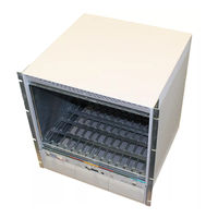
Nortel 5000 Installing (124 pages)
Brand:
Nortel
| Category:
Network Hardware
| Size: 3 MB
Table of Contents
Table of Contents
7
Preface
15
Before You Begin
15
Text Conventions
16
Acronyms
16
Related Publications
17
How to Get Help
18
Installing the Contivity 5000 Chassis
21
Description of the Contivity 5000
21
Figure 1 Front View of the Contivity 5000
22
Preparing to Install the Contivity 5000
23
Shipment Contents
23
Table 1 Items Shipped with the Contivity 5000
23
Additional Equipment
24
Cables
24
Hardware for Mounting the Chassis in an Equipment Rack
25
Site Requirements
25
Installing the Chassis
25
Installing the Chassis on a Flat Surface
25
Installing the Chassis in an Equipment Rack
26
Figure 2 Placement of Rubber Feet on the Bottom of the Chassis
26
Rack-Mount Recommendations
27
Attaching the Shelf in the Equipment Rack
27
Figure 3 Attaching the Cage Nuts to the Rack
27
Figure 4 Installing the Shelf in the Equipment Rack
28
Figure 5 Attaching the Rack-Mount Brackets to the Rear of the Equipment Rack
29
Mounting the Chassis in the Equipment Rack
30
Figure 6 Removing the Front Bezel
30
Figure 7 Replacing the Front Bezel
31
Cabling the Gateway and Turning the Power on
33
Connecting Communications Cables
34
Table 2 Interfaces and Cables for the Contivity 5000
34
Figure 8 Rear View of the Contivity 5000
35
Connecting the Power Cords
36
Table 3 Power Cord Requirements
36
Verifying a Successful Installation
37
Understanding the Leds
38
Front Panel Leds
38
Figure 9 Front Panel Leds
38
Power Supply LED
39
Figure 10 Power Supply LED
39
Table 4 Front Panel LED Indicators
39
Leds on the System 1000BASE-T Ethernet Port
40
Figure 11 Leds on the System 1000BASE-T Ethernet Port
40
Table 5 Power Supply LED
40
Table 6 LED Indicators on the System 1000BASE-T Ethernet Port
40
Leds on the System 10/100BASE Ethernet Port
41
Figure 12 Leds on the System 10/100BASE Ethernet Port
41
Table 7 LED Indicators on the System 10/100BASE Ethernet Port
41
10/100BASE Ethernet Interface Card Leds
42
Figure 13 Leds on the 10/100BASE Ethernet Interface Card
42
Table 8 LED Indicators on the 10/100BASE Ethernet Interface Card
42
1000BASE-T Ethernet Interface Card Leds
43
Figure 14 Leds on the 1000BASE-T Ethernet Interface Card
43
Table 9 LED Indicators on the 1000BASE-T Ethernet Interface Card
43
1000BASE-SX Ethernet Interface Card LED
44
Figure 15 LED on the 1000BASE-SX Ethernet Interface Card
44
Table 10 LED Indicator on the 1000BASE-SX Ethernet Interface Card
44
56/64K CSU/DSU WAN Interface Card Leds
45
Figure 16 Leds on the 56/64K CSU/DSU WAN Interface Card
45
Table 11 LED Indicators on the 56/64K CSU/DSU WAN Interface Card
45
ADSL WAN Interface Card Leds
46
Figure 17 Leds on the ADSL WAN Interface Card
46
Table 12 LED Indicators on the ADSL WAN Interface Card
46
T1/E1 CSU/DSU WAN Interface Card Leds
47
Figure 18 Leds on the T1/E1 CSU/DSU WAN Interface Card
47
Table 13 LED Indicators on the T1/E1 CSU/DSU WAN Interface Card
47
Quad T1/E1 CSU/DSU WAN Interface Card Leds
48
Figure 19 Leds on the Quad T1/E1 CSU/DSU WAN Interface Card
48
Table 14 LED Indicators on the Quad T1/E1 CSU/DSU WAN Interface Card
48
Single V.35/X.21 WAN Interface Card Leds
49
Figure 20 Leds on the Single V.35/X.21 WAN Interface Card
49
Table 15 LED Indicators on the Single V.35/X.21 WAN Interface Card
49
SSL VPN Module 1000 Leds
50
Figure 21 Leds on the SSL VPN Module 1000
50
Table 16 LED Indicators on the SSL VPN Module 1000
50
Configuring the Management IP Interface
51
Required Information
52
Configuring the Management IP Address
53
Testing the Configuration
57
Figure 22 Welcome Screen
58
Troubleshooting
59
Installing Option Cards and Field Replaceable Units
61
Preparing to Install Hardware Options
62
Option Cards, Dimms, and Fan Trays
62
Power Supplies
62
Hard Disk Drives
62
Shutting down the System to Add or Replace Hardware
63
Removing the Front Bezel and Top Cover
64
Figure 23 Removing the Front Bezel
64
Figure 24 Removing the Top Cover
66
Figure 25 Location of Option Cards, Dimms, and Fan Trays on the System Board
67
Attaching the Antistatic Wrist Strap
68
Figure 26 Location of the Grounding Jack for the Antistatic Wrist Strap
68
Installing and Replacing Option Cards
69
Considerations for Installing Option Cards
69
Figure 27 Contivity 5000 Option Card Slots and Buses
69
Table 17 Supported Option Cards for the Contivity 5000
70
Table 18 Optimal Placement of Option Cards in the Contivity 5000
71
Figure 28 Flowchart for Option Card Installation in the Contivity 5000
72
Support for 16 I/O Ports
73
Installing and Replacing an Option Card
73
Figure 29 Installing and Removing an Option Card
74
Figure 30 Replacing the Front Bezel
75
Installing and Replacing Dimms
76
Considerations for Installing Dimms
76
Figure 31 DIMM Memory Banks on the Contivity 5000 Motherboard
76
Figure 32 DIMM Label: Example 1
77
Figure 33 DIMM Label: Example 2
77
Installing Dimms
78
Figure 34 Installing and Removing a DIMM
79
Replacing a Power Supply
80
Figure 35 Location of the Contivity 5000 Power Supplies
80
Figure 36 Removing a Power Supply
82
Figure 37 Inserting a Power Supply
82
Replacing a Hard Disk Drive
83
Figure 38 Location of the Contivity 5000 Hard Disk Drives
83
Figure 39 Removing a Hard Disk Drive
85
Figure 40 Inserting a Hard Disk Drive
86
Replacing a Fan Tray
87
Figure 41 Location of the Contivity 5000 Fan Trays
87
Figure 42 Removing a Fan Tray
88
Figure 43 Installing a Fan Tray
90
Technical Specifications
93
Chassis Specifications
93
Table 19 Physical, Electrical, and Environmental Specifications
93
System Ports
94
1000BASE-T Ethernet LAN Port
94
10/100BASE Ethernet LAN Port
95
Table 20 1000BASE-T Ethernet Port Pinouts
95
Serial Port
96
Table 21 10/100BASE Ethernet Port Pinouts
96
Modem Cable Specifications
97
Figure 44 Modem Cable (9-Pin D-Sub Plug to RS-232-C Modem Plug)
97
Table 22 Multiple DB9 and DB25 Connector Pinouts
97
Hardware Option Cards
98
Table 23 Modem Cable Pinouts
98
Contivity Security Accelerator (CSA) and Hardware Accelerator Cards
99
SSL VPN Module 1000
100
Figure 45 SSL VPN Module 1000
100
10/100BASE Ethernet Interface Card
101
1000BASE-T Ethernet Interface Card
101
Figure 46 10/100BASE Ethernet Interface Card
101
Figure 47 1000BASE-T Ethernet Interface Card
101
1000BASE-SX Ethernet Interface Card
102
Figure 48 1000BASE-SX Ethernet Interface Card
102
56/64K CSU/DSU WAN Interface Card
103
Figure 49 56/64K CSU/DSU WAN Interface Card
103
Table 24 56/64K CSU/DSU Cable Pinouts for Crossover Connection
104
Table 25 56/64K CSU/DSU Cable Pinouts for Straight-Through Connection
104
ADSL WAN Interface Card
105
Figure 50 ADSL WAN Interface Card
105
Table 26 ADSL Cable Pinouts
105
ISDN BRI Interface Card
106
Figure 51 ISDN BRI S/T Interface Card
106
Figure 52 ISDN BRI U Interface Card
106
Table 27 ISDN BRI S/T Cable Pinouts
107
Table 28 ISDN BRI U Cable Pinouts
107
T1/E1 CSU/DSU WAN Interface Card
108
Figure 53 T1/E1 CSU/DSU WAN Interface Card
108
Table 29 T1/E1 CSU/DSU Cable Pinouts for Crossover Connection
109
Table 30 T1/E1 CSU/DSU Cable Pinouts for Straight-Through Connection
109
Quad T1/E1 CSU/DSU WAN Interface Card
110
Figure 54 Quad T1/E1 CSU/DSU WAN Interface Card
110
V.90 Modem Interface Card
111
Single V.35/X.21 WAN Interface Card
111
Figure 55 V.90 Modem Interface Card
111
Figure 56 Single V.35/X.21 WAN Interface Card
111
Table 31 V.90 Modem Cable Pinouts
111
Table 32 V.35 Cable Pinouts
112
Table 33 X.21 Cable Pinouts
113
Dual V.35 WAN Interface Card
115
Figure 57 Dual V.35 WAN Interface Card
115
Table 34 DB26-To-V.35 Cable Pinouts
116
HSSI WAN Interface Card
117
Figure 58 HSSI WAN Interface Card
117
Table 35 T3 Cable Pinouts
117
Index
119
Nortel 5000 Installing (158 pages)
Hardware Options for the Contivity Secure IP Services Gateway
Brand:
Nortel
| Category:
Switch
| Size: 2 MB
Table of Contents
Table of Contents
7
Preface
17
Before You Begin
17
Text Conventions
18
Acronyms
18
Related Publications
19
How to Get Help
21
Contivity 600 Option Installation
23
Shutting down the System to Add or Replace Hardware
24
Opening the Contivity 600
24
Figure 1 Removing the Screws from the Bottom of the Contivity 600
25
Figure 2 Removing the Chassis from the Steel Enclosure
26
Figure 3 Contivity 600 System Board
27
Installing and Replacing an Option Card
28
Figure 4 Removing the Blank Bracket from the Option Card Slot
29
Figure 5 Inserting the Option Card
30
Figure 6 Securing the Option Card in the Slot
31
Figure 7 Replacing the Chassis in the Steel Enclosure
31
Replacing a DIMM
32
Figure 8 Installing a DIMM
33
Contivity 1100 Option Installation
35
Table 1 Supported Option Cards for the Contivity 1100
35
Figure 9 Contivity 1100 System Board
37
Contivity 1700 and 1600 Option Installation
39
Shutting down the System to Add or Replace Hardware
40
Removing the Front Bezel and Top Cover
41
Figure 10 Removing the Front Bezel
41
Figure 11 Removing the Top Cover
42
Figure 12 Location of Option Card Slots and Dimms on the System Board
43
Attaching the Antistatic Wrist Strap
44
Figure 13 Location of the Grounding Jack for the Antistatic Wrist Strap
44
Installing and Replacing Option Cards
45
Table 2 Supported Option Cards for the Contivity 1700
45
Table 3 Supported Option Cards for the Contivity 1600
45
Figure 14 Removing an Option Card or a Filler Panel
47
Figure 15 Installing an Option Card
48
Installing and Replacing Dimms
49
Figure 16 Replacing the Front Bezel
49
Figure 17 Installing and Removing a DIMM in a Contivity 1700 or 1600
51
Figure
51
Contivity 1740 Option Installation
53
Shutting down the System to Add or Replace Hardware
54
Removing the Front Bezel and Top Cover
55
Figure 18 Removing the Front Bezel
55
Figure 19 Removing the Top Cover
56
Figure 20 Location of Option Card and DIMM Slots on the System Board
57
Attaching the Antistatic Wrist Strap
58
Figure 21 Location of the Grounding Jack for the Antistatic Wrist Strap
58
Installing and Replacing Option Cards
59
Table 4 Supported Option Cards for the Contivity 1740
59
Figure 22 Installing and Removing an Option Card
61
Figure 23 Replacing the Front Bezel
62
Installing and Replacing Dimms
63
Figure 24 Installing and Removing a DIMM
64
Contivity 2700 and 2600 Option Installation
67
Shutting down the System to Add or Replace Hardware
68
Removing the Front Bezel and Top Cover
69
Figure 25 Removing the Front Bezel
69
Figure 26 Removing the Top Cover
70
Figure 27 Location of Option Card Slots and Dimms on the System Board
71
Attaching the Antistatic Wrist Strap
72
Figure 28 Location of the Grounding Jack for the Antistatic Wrist Strap
72
Installing and Replacing Option Cards
73
Table 5 Supported Option Cards for the Contivity 2700
73
Table 6 Supported Option Cards for the Contivity 2600
74
Figure 29 Installing and Removing an Option Card
75
Installing and Replacing Dimms
77
Table 7 Base and Maximum Memory for the Contivity 2600 and 2700
77
Contivity 4500 Option Installation
81
Opening the Contivity 4500
81
Figure 33
83
Contivity 4500 System Board Layout
84
Installing and Replacing Option Cards
86
Table 8 Supported Option Cards for the Contivity 4500
86
Installing and Replacing Dimms
88
Replacing a Power Supply
90
Figure 37
90
Replacing a Hard Disk Drive
91
Figure
91
Contivity 4600 Option Installation
93
Opening the Contivity 4600
93
Contivity 4600 System Board Layout
96
Installing and Replacing Option Cards
97
Table 9 Supported Option Cards for the Contivity 4600
97
Installing and Replacing Dimms
99
Figure
99
Replacing a Power Supply
100
Figure
100
Replacing a Hard Disk Drive
102
Contivity 5000 Option Installation
105
Preparing to Install Hardware Options
106
Option Cards, Dimms, and Fan Trays
106
Power Supplies
106
Removing the Front Bezel
108
Removing the Top Cover
110
Table 10 Supported Option Cards for the Contivity 5000
113
Replacing the Front Bezel
116
Removing a Power Supply
121
Removing a Hard Disk Drive
124
Removing a Fan Tray
127
10/100BASE Ethernet Interface Card
133
Table 11 10/100BASE Ethernet Port Pinouts (All Models Except Contivity 1100)
134
Table 12 10/100BASE Ethernet Port Pinouts (Contivity 1100 Only)
134
1000BASE-T Ethernet Interface Card
135
1000BASE-SX Ethernet Interface Card
136
Table 13 1000BASE-T Ethernet Port Pinouts
136
Figures
137
Figure 65 ADSL WAN Interface Card
137
Figure 66 ISDN BRI S/T Interface Card
138
Figure 67 ISDN BRI U Interface Card
138
Table 14 ADSL Cable Pinouts
138
Table 15 ISDN BRI S/T Cable Pinouts
139
Table 16 ISDN BRI U Cable Pinouts
139
Figure 68 T1/E1 CSU/DSU WAN Interface Card
140
Table 17 T1/E1 CSU/DSU Cable Pinouts for Crossover Connection
141
Table 18 T1/E1 CSU/DSU Cable Pinouts for Straight-Through Connection
141
Figure 69 Quad T1/E1 CSU/DSU WAN Interface Card
142
Figure 70 V.90 Modem Interface Card
143
Figure 71 Single V.35/X.21 WAN Interface Card
143
Table 19 V.90 Modem Cable Pinouts
143
Table 20 V.35 Cable Pinouts
144
Table 21 X.21 Cable Pinouts
145
Figure 72 Dual V.35 WAN Interface Card
147
Table 22 DB26-To-V.35 Cable Pinouts
148
Figure 73 HSSI WAN Interface Card
149
Table 23 T3 Cable Pinouts
149
Figure 74 Serial Cable Adapter for Connection to Modem (DB9-To-DB25)
151
Table 24 Null Modem Adapter Cable Pinouts
152
Advertisement
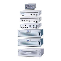
Nortel 5000 User Manual (67 pages)
VPN Router v7.05; Client Workstation v7.11 Security Target, Version 3.9
Brand:
Nortel
| Category:
Network Router
| Size: 1 MB
Table of Contents
Revision History
2
Table of Contents
3
Table of Figures
4
Table of Tables
4
1 Security Target Introduction
5
Purpose
5
Security Target, TOE and CC Identification and Conformance
5
Able 1 - St, Toe, and CC Identification and Onformance
5
Conventions, Acronyms, and Terminology
6
Conventions
6
Terminology
6
Table 2 - Terminology
6
2 Toe Description
8
Product Type
8
Product Description
8
Vpn Client Deployment Configuration of the Toe
8
Figure 2 - Branch Office Deployment Configuration of the Toe
9
Toe Boundaries and Scope
10
Physical Boundary
10
Figure 3 - Physical Toe Boundary
10
Figure 4 - Physical Toe Boundary in Branch Office Tunnel Mode
10
Logical Boundary
11
Toe Logical Boundary
12
Toe Logical Boundary in Branch Office Tunnel Mode
12
Excluded TOE Functionality
15
3 Toe Security Environment
16
Assumptions
16
Threats to Security
16
Threats Addressed by the TOE
17
Threats Addressed by the TOE Environment
17
4 Security Objectives
18
Security Objectives for the Toe
18
Security Objectives for the Environment
19
IT Security Objectives
19
Non-IT Security Objectives
19
5 It Security Requirements
20
Toe Security Functional Requirements
20
Able 3 - Toe Security Functional Requirements
20
Class FAU: Security Audit
22
Table 4 - Auditable Events
22
Class FCS: Cryptographic Support
24
Class FDP: User Data Protection
27
Class FIA: Identification and Authentication
31
Class FMT: Security Management
33
Class FPT: Protection of the TSF
37
Class FTP: Trusted Path/Channels
38
Security Functional Requirements on the It Environment
39
Able 5 - It Environment Security Functional Requirements
39
Assurance Requirements
41
Table 6 - Assurance Components
41
6 Toe Summary Specification
42
Toe Security Functions
42
Table 7 - Mapping of Toe Security Functions to Security Functional Requirements
42
Security Audit
43
Cryptographic Support
45
Table 8 - Fips-V
45
User Data Protection
46
Identification and Authentication
47
Security Management
47
Protection of the TOE Security Functions
48
Trusted Path/Channels
49
Toe Security Assurance Measures
49
Table 9 - Assurance Measures Mapping to Toe Security Assurance Requirements (Sar S )
49
7 Protection Profile Claims
51
Protection Profile Reference
51
8 Rationale
52
Security Objectives Rationale
52
Table 10 - Relationship of Security Threats to Objectives
52
Security Functional Requirements Rationale
55
Table 11 - Relationship of Security Requirements to Objectives
56
Security Assurance Requirements Rationale
60
Rationale for Strength of Function
60
Dependency Rationale
60
Table 12 - Functional Requirements Dependencies
60
Toe Summary Specification Rationale
62
TOE Summary Specification Rationale for the Security Functional Requirements
62
Table 13 - Mapping of Security Functional Requirements to Toe Security Functions
62
TOE Summary Specification Rationale for the Security Assurance Requirements
63
Strength of Function
65
9 Acronyms
66
Table 14 - Acronyms
66
Nortel 5000 Installation Manual (66 pages)
Ethernet Routing Switch SFPs and XFPs
Brand:
Nortel
| Category:
Switch
| Size: 0 MB
Table of Contents
Table of Contents
3
New in this Release
5
Features
5
Support for Additional Sfps
5
Introduction
7
Safety and Equipment Care Information
9
Handling, Safety, and Environmental Guidelines
9
Electrostatic Discharge Prevention
9
Care of Fiber Optic Equipment
10
Fiber Optic Cable Care
10
Fiber Optic Connector Care
11
Cleaning Single Connectors
12
Procedure Steps
13
Cleaning Duplex Connectors
13
Cleaning Receptacles
14
Product Safety Warnings and Information
16
ESD and Installation Caution Messages
16
Laser Safety Warnings
17
Small Form Factor Pluggable Transceivers
21
Selecting an SFP
21
Job Aid
22
Job Aid
23
Installing an SFP
24
Job Aid
26
Removing an SFP
27
SFP Specifications
29
SFP Labels
30
General SFP Specifications
30
100BASE-FX SFP Specifications
31
T1 SFP Specifications
31
T1 SFP-Default Settings
34
1000BASE-T SFP Specifications
35
1000BASE-SX (LC) SFP Specifications
35
1000BASE-SX (MT-RJ) SFP Specifications
36
1000BASE-LX SFP Specifications
37
1000BASE-XD CWDM SFP Specifications
37
1000BASE-ZX CWDM SFP Specifications
38
1000BASE-SX DDI SFP Specifications
39
1000BASE-LX DDI SFP Specifications
39
Aa1419048-E6
39
Aa1419049-E6
39
1000BASE-XD DDI 1310 Nm SFP Specifications
40
1000BASE-XD DDI 1550 Nm SFP Specifications
40
Aa1419050-E6
40
Aa1419051-E6
40
1000BASE-ZX DDI SFP Specifications
41
Aa1419052-E6
41
1000BASE-XD DDI CWDM SFP Specifications
42
1000BASE-ZX DDI CWDM SFP Specifications
42
AA1419053-E6 to AA1419060-E6
42
AA1419061-E6 to AA1419068-E6
42
Specifications
42
1000BASE-BX10 DDI SFP Specifications
43
1000BASE-BX40 DDI SFP Specifications
44
1000BASE-EX DDI SFP Specifications
45
Gigabit Small Form Factor Pluggable Transceivers
47
Selecting an XFP
47
Job Aid
48
Installing an XFP
49
Procedure Steps
50
Removing an XFP
51
XFP Specifications
53
XFP Labels
53
General XFP Specifications
54
10GBASE-SR XFP Specifications
54
10GBASE-LRM XFP Specifications
56
10GBASE-LR/LW XFP Specifications
58
10GBASE-ER/EW XFP Specifications
60
10GBASE-ZR/ZW XFP Specifications
61
Index
63
Nortel 5000 Release Notes (54 pages)
Ethernet Routing Switch
Brand:
Nortel
| Category:
Network Router
| Size: 0 MB
Table of Contents
Restricted Rights Legend
2
Table of Contents
5
New in this Release
7
Features
7
Other Changes
7
New Hardware
7
File Names for Upgrade
8
Windows Vista
8
Hardware and Software Compatibility
8
Complete Integration of All Release 5.1 Features
8
Document Changes
8
Introduction
9
Important Notices and New Features
11
New Features in Release 6.0
11
New Hardware in Release 6.0
11
Software Features in Release 6.0
12
File Names for this Release
14
Supported Software and Hardware Capabilities
16
Nortel Ethernet Routing Switch 5520 Phone Dongle
17
Ensuring Device Manager Online Help Displays Correctly
17
Additional Information for the Feature Software License File
18
Upgrading Software
18
Supported Standards, Mibs, and Rfcs
21
Standards
21
Rfcs
21
Resolved Issues
25
Issues Resolved in Release 6.0
25
Known Issues and Limitations
29
Known Issues
29
VLACP Issue
44
Port or Ifindex Offset Issue
45
Filter Resource Consumption
45
Masks and Filters Inventory Check
47
Qos Interface Security Application
51
Nortel Ethernet Routing Switch 5000 Series
52
Release Notes — Release 6.0 NN47200-400 04.01 Standard 6.0 12 December
52
Release Notes - Release 6.0
54
Copyright © 2008, Nortel Networks
54
Advertisement
Related Products
Nortel 5500 series
Nortel 50 Series
Nortel BayStack 5000-SRC
Nortel BayStack 5000-SSC
Nortel 5100 Series Release 2.3.3
Nortel 553-3901-200
Nortel ERS 5698-TFD
Nortel Application Server 53r 53
Nortel BayStack 5510-48T
Nortel 5114
Nortel Categories
IP Phone
Telephone
Switch
Software
Server
More Nortel Manuals
Login
Sign In
OR
Sign in with Facebook
Sign in with Google
Upload manual
Upload from disk
Upload from URL