Nortel Contivity 5000 Installing
Hide thumbs
Also See for Contivity 5000:
- Installing (158 pages) ,
- Installation manual (66 pages) ,
- Release notes (54 pages)

Related Manuals for Nortel Contivity 5000


Summary of Contents for Nortel Contivity 5000
- Page 1 Part No. 315990-D Rev 00 June 2004 600 Technology Park Drive Billerica, MA 01821-4130 Installing the Contivity 5000 *315990-D_Rev_00*...
- Page 2 In the interest of improving internal design, operational function, and/or reliability, Nortel Networks Inc. reserves the right to make changes to the products described in this document without notice. Nortel Networks Inc. does not assume any liability that may occur due to the use or application of the product(s) or circuit layout(s) described herein.
- Page 3 Canada requirements only Canadian Department of Communications Radio Interference Regulations This digital apparatus (Contivity 5000) does not exceed the Class A limits for radio-noise emissions from digital apparatus as set out in the Radio Interference Regulations of the Canadian Department of Communications.
- Page 4 30 days of purchase to obtain a credit for the full purchase price. “Software” is owned or licensed by Nortel Networks, its parent or one of its subsidiaries or affiliates, and is copyrighted and licensed, not sold. Software consists of machine-readable instructions, its components, data, audio-visual content (such as images, text, recordings or pictures) and related licensed materials including all whole or partial copies.
- Page 5 12.212 (for non-DoD entities) and 48 C.F.R. 227.7202 (for DoD entities). Customer may terminate the license at any time. Nortel Networks may terminate the license if Customer fails to comply with the terms and conditions of this license. In either event, upon termination, Customer must either return the Software to Nortel Networks or certify its destruction.
- Page 6 315990-D Rev 00...
-
Page 7: Table Of Contents
Chapter 1 Installing the Contivity 5000 chassis ......21 Description of the Contivity 5000 ......... 21 Preparing to install the Contivity 5000 . - Page 8 8 Contents Understanding the LEDs ..........38 Front panel LEDs .
- Page 9 Index ............119 Installing the Contivity 5000...
- Page 10 10 Contents 315990-D Rev 00...
- Page 11 Figure 1 Front view of the Contivity 5000 ....... . 22 Figure 2 Placement of rubber feet on the bottom of the chassis .
- Page 12 Inserting a hard disk drive ........86 Figure 41 Location of the Contivity 5000 fan trays ......87 Figure 42 Removing a fan tray .
- Page 13 Tables Table 1 Items shipped with the Contivity 5000 ......23 Table 2 Interfaces and cables for the Contivity 5000 ..... . . 34 Table 3 Power cord requirements .
- Page 14 14 Tables Table 30 T1/E1 CSU/DSU cable pinouts for straight-through connection ..109 Table 31 V.90 modem cable pinouts ........111 Table 32 V.35 cable pinouts .
-
Page 15: Preface
17.) Before you begin This guide is intended for qualified service personnel who are installing the Contivity 5000 for the first time or who need to install or replace any of the following field replaceable units (FRUs): • LAN, WAN, and serial interface cards •... -
Page 16: Text Conventions
Preface Text conventions This guide uses the following text conventions: Indicates command names and options and text that bold Courier text you need to enter. Example: Use the command. show health Example: Enter terminal paging {off | on} italic text Indicates new terms and book titles. -
Page 17: Related Publications
Related publications For complete information about configuring, monitoring, and managing the Contivity 5000, refer to the following publications (included on the software CD): • Release notes provide the latest information, including brief descriptions of the new features, problems fixed in this release, and known problems and workarounds. -
Page 18: How To Get Help
URL to download a free copy of the Adobe Acrobat Reader. How to get help If you purchased a service contract for your Nortel Networks product from a distributor or authorized reseller, contact the technical support staff for that distributor or reseller for assistance. - Page 19 Preface An Express Routing Code (ERC) is available for many Nortel Networks products and services. When you use an ERC, your call is routed to a technical support person who specializes in supporting that product or service. To locate an ERC for your product or service, go to the http://www.nortelnetworks.com/help/contact/...
- Page 20 Preface 315990-D Rev 00...
-
Page 21: Installing The Contivity 5000 Chassis
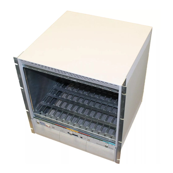
The Contivity 5000 is a high-performance, business-class IP services gateway that enables scalable, secure, and robust IP VPNs across the public data network. The Contivity 5000 uses the infrastructure of the Internet to replace traditional remote access gear. The Contivity 5000 provides routing, firewall, bandwidth management, encryption, authentication, and data integrity services to ensure secure tunneling across IP networks and the Internet. -
Page 22: Figure 1 Front View Of The Contivity 5000
LAN port on the base system • One 10/100BASE Ethernet LAN port on the base system • One serial port for out-of-band management of the Contivity 5000 • Dual redundant 350-watt hot-swappable power supplies with dual AC input connections •... -
Page 23: Preparing To Install The Contivity 5000
Chapter 1 Installing the Contivity 5000 chassis 23 Preparing to install the Contivity 5000 Before you begin the installation, verify that: • Your shipment is complete and undamaged. • You have the cables, tools, and other equipment that you need. -
Page 24: Additional Equipment
“How to get help” on page 18). Additional equipment You may need items that are not included in the Contivity 5000 shipping container. Before you begin the installation, make sure that you have all the cables, tools, and other equipment that you need. -
Page 25: Hardware For Mounting The Chassis In An Equipment Rack
26). Installing the chassis on a flat surface If you decide to place the Contivity 5000 on a flat surface, make sure that the surface is large enough for the gateway and sturdy enough to support the combined weight of the Contivity 5000 and the cables that you attach to it. -
Page 26: Installing The Chassis In An Equipment Rack
26 Chapter 1 Installing the Contivity 5000 chassis The Contivity 5000 accessory kit includes four rubber feet that can be attached to the bottom of the chassis. Figure 2 shows the placement of these rubber feet. Figure 2 Placement of rubber feet on the bottom of the chassis... -
Page 27: Rack-Mount Recommendations
Attaching the shelf in the equipment rack The Contivity 5000 ships with a rack-mount shelf to support the chassis in the equipment rack. To attach the shelf to the equipment rack: If the holes in the rack’s vertical supports are not threaded, attach a cage nut in... -
Page 28: Figure 4 Installing The Shelf In The Equipment Rack
28 Chapter 1 Installing the Contivity 5000 chassis Position the rack-mount shelf inside the rack as shown in Figure To ease the shelf into the rack, tilt it slightly or squeeze its sides together gently before moving it into the rack. -
Page 29: Figure 5 Attaching The Rack-Mount Brackets To The Rear Of The Equipment Rack
Chapter 1 Installing the Contivity 5000 chassis 29 b Align each bracket with the rear of the rack-mount shelf (Figure Position the bracket between the shelf and the equipment rack. Figure 5 Attaching the rack-mount brackets to the rear of the equipment rack 11046FA Insert two of the supplied 3/8 in. -
Page 30: Mounting The Chassis In The Equipment Rack
For this reason, two people should install the system in the equipment rack. To install the Contivity 5000 in the equipment rack: With two people facing the front of the equipment rack, set the Contivity 5000 on the rack-mount shelf (Figure Remove the front bezel from the Contivity 5000. -
Page 31: Figure 7 Replacing The Front Bezel
Chapter 1 Installing the Contivity 5000 chassis 31 Insert one of the supplied 1/2-in. truss screws through the bottom hole on each side of the shelf into the hole in the rack and tighten the screws (see Figure 4 on page 28). - Page 32 32 Chapter 1 Installing the Contivity 5000 chassis 315990-D Rev 00...
-
Page 33: Cabling The Gateway And Turning The Power On
Contivity 5000. Caution: Connect the cables to the built-in Ethernet ports and to the ports on the interface cards installed in the Contivity 5000 before you plug the power cords into the outlets. -
Page 34: Connecting Communications Cables
Table 2 lists the system ports and the ports provided on the optional interface cards that you can install in the Contivity 5000. The table also indicates whether you can obtain cables for the ports from Nortel Networks. Table 2 Interfaces and cables for the Contivity 5000... -
Page 35: Figure 8 Rear View Of The Contivity 5000
Chapter 2 Cabling the gateway and turning the power on 35 Figure 8 shows the back of the Contivity 5000. All interface cables and the power cords attach to the rear of the gateway. Figure 8 Rear view of the Contivity 5000... -
Page 36: Connecting The Power Cords
Connect each power cord to an AC receptacle on the back of the gateway (see Figure 8 on page 35). Connect each power cord to a power outlet. Caution: You should protect the Contivity 5000 by plugging it into a surge suppressor. 315990-D Rev 00... -
Page 37: Verifying A Successful Installation
Chapter 2 Cabling the gateway and turning the power on 37 Press and release the power switch on the rear of the Contivity 5000 (see Figure 8 on page 35) and wait for the gateway to boot. Note: When you press the power switch, 3 or 4 seconds may elapse before the system power turns on. -
Page 38: Understanding The Leds
LEDs. You can confirm that the LAN and WAN interfaces are cabled properly by examining the LEDs. Front panel LEDs The front panel of the Contivity 5000 has four system LEDs (Figure 9). These LEDs indicate the status of the Contivity 5000. -
Page 39: Power Supply Led
Chapter 2 Cabling the gateway and turning the power on 39 Table 4 describes the LEDs on the Contivity 5000 front panel. Table 4 Front panel LED indicators Indicator Description Alert Yellow A non-fatal alarm condition exists. The yellow alert condition is described in the health check display. -
Page 40: Leds On The System 1000Base-T Ethernet Port
LEDs on the system 1000BASE-T Ethernet port Figure 11 shows the LEDs for the 1000BASE-T Ethernet port located on the rear of the Contivity 5000. Figure 11 LEDs on the system 1000BASE-T Ethernet port 10/100/1000 Activity/... -
Page 41: Leds On The System 10/100Base Ethernet Port
Chapter 2 Cabling the gateway and turning the power on 41 LEDs on the system 10/100BASE Ethernet port Figure 12 shows the LEDs for the 10/100BASE Ethernet port located on the rear of the Contivity 5000. Figure 12 LEDs on the system 10/100BASE Ethernet port Activity/Link 10/100... -
Page 42: 10/100Base Ethernet Interface Card Leds
42 Chapter 2 Cabling the gateway and turning the power on 10/100BASE Ethernet interface card LEDs Figure 13 shows the LEDs on the 10/100BASE Ethernet interface card. Figure 13 LEDs on the 10/100BASE Ethernet interface card Activity/Link 10/100 Mb/s CS260009A Table 8 describes the LEDs on the 10/100BASE Ethernet interface card. -
Page 43: 1000Base-T Ethernet Interface Card Leds
The port is not linked to a valid partner. 10/100/1000 The LAN port is operating at 10 Mb/s. Green The LAN port is operating at 100 Mb/s. Orange The LAN port is operating at 1000 Mb/s. Installing the Contivity 5000... -
Page 44: 1000Base-Sx Ethernet Interface Card Led
44 Chapter 2 Cabling the gateway and turning the power on 1000BASE-SX Ethernet interface card LED Figure 15 shows the LED on the 1000BASE-SX Ethernet interface card. Figure 15 LED on the 1000BASE-SX Ethernet interface card ACT/LNK 11288EA Table 10 describes the LED on the 1000BASE-SX Ethernet interface card. -
Page 45: 56/64K Csu/Dsu Wan Interface Card Leds
Red alarm LED is lit when a loss-of-signal (LOS) or out-of-frame (OOF) condition is detected on the receive signal. Yellow Yellow alarm LED is lit when the far-end equipment is in the red alarm condition. Green Normal operation. Installing the Contivity 5000... -
Page 46: Adsl Wan Interface Card Leds
46 Chapter 2 Cabling the gateway and turning the power on ADSL WAN interface card LEDs Figure 17 shows the LEDs on the ADSL WAN interface card. Figure 17 LEDs on the ADSL WAN interface card Tx/Rx LED Tx/Rx ADSL CONN CONN LED 10972EA... -
Page 47: T1/E1 Csu/Dsu Wan Interface Card Leds
Blue alarm LED is lit when receiving an upstream failure denoted by an alarm indication signal (AIS). LED 3 Yellow Yellow alarm LED is lit when the far-end equipment is in the red alarm condition. LED 4 Green Normal operation. Installing the Contivity 5000... -
Page 48: Quad T1/E1 Csu/Dsu Wan Interface Card Leds
48 Chapter 2 Cabling the gateway and turning the power on Quad T1/E1 CSU/DSU WAN interface card LEDs Figure 19 shows the LEDs on the quad T1/E1 CSU/DSU WAN interface card. Figure 19 LEDs on the quad T1/E1 CSU/DSU WAN interface card LED 1 LED 2 LED 3... -
Page 49: Single V.35/X.21 Wan Interface Card Leds
The signals CDC and DSR are on between the DSU and the adapter. LED 2 detects receive link status. LED 3 Green Power to the adapter is on and the onboard microcode is loaded. LED 4 Green Cable is detected. Installing the Contivity 5000... -
Page 50: Ssl Vpn Module 1000 Leds
50 Chapter 2 Cabling the gateway and turning the power on SSL VPN Module 1000 LEDs Figure 21 shows the LEDs on the SSL VPN Module 1000. Figure 21 LEDs on the SSL VPN Module 1000 Online Utilization Activity 11356EA Table 16 describes the LEDs on the SSL VPN Module 1000. -
Page 51: Configuring The Management Ip Interface
Configuring the management IP interface This chapter describes how to configure a management IP address, subnet mask, and default gateway address on a newly installed Contivity 5000. After you complete the procedures in this chapter, you will be able to configure and manage the gateway using a Web browser from a PC. -
Page 52: Required Information
IP address for the management interface The management IP address must be accessible from one of the private physical interfaces on the Contivity 5000. For example, if you plan to assign IP address 10.2.3.3 with subnet mask 255.255.0.0 to the private physical interface, the management IP address must reside in the 10.2 network. -
Page 53: Configuring The Management Ip Address
Chapter 3 Configuring the management IP interface 53 Configuring the management IP address You use the serial interface to assign the Contivity 5000 a management IP address and subnet mask so that you can then use a Web browser for management. - Page 54 54 Chapter 3 Configuring the management IP interface The serial main menu appears. Main Menu: System is currently in NORMAL mode. 1) Interfaces 2) Administrator 3) Default Private Route Menu 4) Default Public Route Menu 5) Create A User Control Tunnel (IPsec) Profile 6) Restricted Management Mode FALSE 7) Allow HTTP Management...
- Page 55 The subnet mask prompt appears. Old Subnet Mask = 0.0.0.0 New Subnet Mask = At the New Subnet Mask prompt, type the subnet mask for the management IP address and press Enter. The Speed/Duplex prompt appears. Installing the Contivity 5000...
- Page 56 13 Go to the next section, “Testing the configuration,” to verify that you can access the Contivity 5000 from a Web browser. For detailed information about configuring and managing the Contivity 5000, refer to the documentation on the software CD. 315990-D Rev 00...
-
Page 57: Testing The Configuration
After you assign a management IP address to the Contivity 5000, start your Web browser to verify that you can access the gateway from the browser. To manage the Contivity 5000 using the GUI, your PC must be running one of the following browsers: •... -
Page 58: Figure 22 Welcome Screen
58 Chapter 3 Configuring the management IP interface Figure 22 Welcome screen 315990-D Rev 00... -
Page 59: Troubleshooting
Check the physical connections on the Contivity 5000, especially the LAN cable and both power cords. If you still cannot connect to the Contivity 5000 using a browser, connect a terminal or PC to the gateway with the serial cable and check the management IP address listed in the serial menu (see “Configuring the management IP address”... - Page 60 60 Chapter 3 Configuring the management IP interface 315990-D Rev 00...
-
Page 61: Installing Option Cards And Field Replaceable Units
Chapter 4 Installing option cards and field replaceable units This chapter provides instructions on how to install and replace the following field replaceable units (FRUs) in the Contivity 5000: • LAN, WAN, and serial interface cards • SSL VPN Module 1000 •... -
Page 62: Preparing To Install Hardware Options
If you need to add or replace an option card, pair of DIMMs, or fan tray, see “Shutting down the system to add or replace hardware” on page Power supplies The Contivity 5000 power supplies are hot-swappable. You do not need to shut down the system to replace a power supply. For instructions, see “Replacing a power supply”... -
Page 63: Shutting Down The System To Add Or Replace Hardware
Chapter 4 Installing option cards and field replaceable units 63 Shutting down the system to add or replace hardware Shut down the Contivity 5000 and unplug it to install or replace any of these field replaceable units: • Option card •... -
Page 64: Removing The Front Bezel And Top Cover
Contivity 5000. To remove the front bezel: Shut down the Contivity 5000 using the Web GUI or the command line interface and then unplug it as described in “Shutting down the system to add or replace hardware”... - Page 65 “Replacing a hard disk drive” on page If the Contivity 5000 is installed in an equipment rack, you must remove it from the rack to add or replace DIMMs, option cards, or fan trays. To remove the chassis from the rack: At the front of the chassis, remove the two 1/2-in.
-
Page 66: Figure 24 Removing The Top Cover
Figure 24 Removing the top cover 10966FA Lift the lid 2 or 3 inches and pull it toward you to remove it from the chassis. The Contivity 5000 system board is now exposed. Figure 25 shows the location of the option card slots, the DIMM slots, and the fan trays on the system board. -
Page 67: Figure 25 Location Of Option Cards, Dimms, And Fan Trays On The System Board
Danger: In spite of the above warning, which is mandated for regulatory approval, you should not change the battery. If you suspect a dead battery, contact Nortel Networks Customer Support. Installing the Contivity 5000... -
Page 68: Attaching The Antistatic Wrist Strap
68 Chapter 4 Installing option cards and field replaceable units Attaching the antistatic wrist strap Nortel Networks ships the Contivity 5000 with an antistatic wrist strap. The antistatic wrist strap directs the discharge of static electricity from your body to the chassis of the gateway to avoid damage to sensitive electronic components. -
Page 69: Installing And Replacing Option Cards
This section provides information about the optimal placement of option cards in the Contivity 5000 and instructions for installing option cards. Considerations for installing option cards The Contivity 5000 has six slots for option cards (see Figure 25 on page 67). -
Page 70: Table 17 Supported Option Cards For The Contivity 5000
1, a 1000BASE-T card installed in slot 2 runs at 32-bit/33-MHz, not at the bus speed of 64-bit/100-MHz. Table 17 lists all option cards that you can install in the Contivity 5000. Table 18 provides guidelines for the placement of the cards in the chassis. -
Page 71: Table 18 Optimal Placement Of Option Cards In The Contivity 5000
Table Figure 28 is a flowchart that illustrates the placement of option cards in the Contivity 5000. The typical order for installing option cards is as follows: Hardware accelerator cards, from highest speed to lowest speed: SSL VPN Module 1000... -
Page 72: Figure 28 Flowchart For Option Card Installation In The Contivity 5000
72 Chapter 4 Installing option cards and field replaceable units Figure 28 Flowchart for option card installation in the Contivity 5000 Begin SSL VPN Install in Module 1000 slot 1. required? Install in slot 6 CSA or H/W choice); slot... -
Page 73: Support For 16 I/O Ports
The Contivity 5000 supports a maximum of 16 I/O ports. This number includes the two built-in LAN ports on the gateway. When you provision a Contivity 5000 with I/O cards, do not exceed the 16-port maximum. For example, the following configuration results in 17 I/O ports: •... -
Page 74: Figure 29 Installing And Removing An Option Card
Using a screwdriver, insert and tighten the 4 screws that secure the cover to the chassis. Warning: The Contivity 5000 weighs approximately 50 pounds (23 kg). Two people are needed to install the gateway in the equipment rack. 315990-D Rev 00... -
Page 75: Figure 30 Replacing The Front Bezel
Chapter 4 Installing option cards and field replaceable units 75 10 With two people facing the front of the equipment rack, set the Contivity 5000 on the rack-mount shelf. 11 Insert one of the 1/2-in. truss screws through the bottom hole on each side of... -
Page 76: Installing And Replacing Dimms
This section provides information about the placement of dual inline memory modules (DIMMs) in the Contivity 5000 and instructions for installing them. Considerations for installing DIMMs The Contivity 5000 has six slots for DIMMs. These six slots are divided into three memory banks (Figure 31). -
Page 77: Figure 32 Dimm Label: Example 1
Figure 32 DIMM label: Example 1 AVM7232R37C2266K0-A Nortel 315774-A 11358EA Figure 33 illustrates a second type of DIMM that you could receive. Figure 33 DIMM label: Example 2 MT9VDDT3272G 265C3 xxxxxx Xxxxxxxxxxxxxx x x xx xxxx 256MB, DDR, 266, CL2.5 11359EA Installing the Contivity 5000... -
Page 78: Installing Dimms
78 Chapter 4 Installing option cards and field replaceable units Installing DIMMs To install or replace a DIMM: Shut down the Contivity 5000 using the Web GUI or the command line interface and then unplug it as described in “Shutting down the system to add or replace hardware”... -
Page 79: Figure 34 Installing And Removing A Dimm
Using a screwdriver, insert and tighten the 4 screws to secure the cover to the chassis. Warning: The Contivity 5000 weighs approximately 50 pounds (23 kg). Two people are needed to install the gateway in the equipment rack. Installing the Contivity 5000... -
Page 80: Replacing A Power Supply
80 Chapter 4 Installing option cards and field replaceable units 11 With two people facing the front of the equipment rack, set the Contivity 5000 on the rack-mount shelf. 12 Insert one of the 1/2-in. truss screws through the bottom hole on each side of... - Page 81 “Shutting down the system to add or replace hardware” on page 63.) To replace a power supply: Attach the antistatic wrist strap that was shipped with the Contivity 5000 (see “Attaching the antistatic wrist strap” on page 68). Remove the failed power supply from the chassis.
-
Page 82: Figure 36 Removing A Power Supply
82 Chapter 4 Installing option cards and field replaceable units Figure 36 Removing a power supply 11008FA Insert the replacement power supply into the chassis. Guide the power supply into the slot (Figure 37). Figure 37 Inserting a power supply 11009FA b Push the power supply all the way into the slot. -
Page 83: Replacing A Hard Disk Drive
5000 automatically redistributes the power load between the two power supplies. Replacing a hard disk drive The Contivity 5000 ships with dual hard disk drives installed in the chassis. The hard disk drives are accessible from the front of the chassis (Figure 38). - Page 84 You can hot-swap the backup disk drive only. To replace the primary disk drive, you must first shut down the system. Note: If you do not want to shut down the Contivity 5000 to replace the primary disk drive, you can reboot the system from the backup disk. For example, if disk 0 is the primary disk, reboot the gateway from disk 1.
-
Page 85: Figure 39 Removing A Hard Disk Drive
“Removing the front bezel and top cover” on page 64). Attach the antistatic wrist strap that was shipped with the Contivity 5000 (see “Attaching the antistatic wrist strap” on page 68). Insert the hard disk drive key into the lock and turn it to the right (Figure 39). -
Page 86: Figure 40 Inserting A Hard Disk Drive
Using the screwdriver, tighten the 2 screws to secure the bezel to the chassis. 10 If you shut down the gateway before you replaced the hard disk drive, press and release the power switch on the rear of the Contivity 5000 (see Figure 8 on page 35) and wait for the gateway to boot. -
Page 87: Replacing A Fan Tray
Chapter 4 Installing option cards and field replaceable units 87 Replacing a fan tray The Contivity 5000 ships with two fan trays installed in the chassis: one tray in the front of the chassis and the other in the rear of the chassis (Figure 41). -
Page 88: Figure 42 Removing A Fan Tray
88 Chapter 4 Installing option cards and field replaceable units To replace a fan tray: Shut down the Contivity 5000 using the Web GUI or the command line interface and then unplug it as described in “Shutting down the system to add or replace hardware”... - Page 89 Note: There is only one type of fan tray for the Contivity 5000. You install the same fan tray in the front or the rear of the chassis.
-
Page 90: Figure 43 Installing A Fan Tray
Warning: The Contivity 5000 weighs approximately 50 pounds (23 kg). Two people are needed to install the gateway in the equipment rack. 15 With two people facing the front of the equipment rack, set the Contivity 5000 on the rack-mount shelf. - Page 91 17 Replace the front bezel (see Figure 30 on page 75). Hold the bezel by its two handles and push it onto the chassis. b Using the screwdriver, tighten the 2 screws to secure the bezel to the chassis. Installing the Contivity 5000...
- Page 92 92 Chapter 4 Installing option cards and field replaceable units 315990-D Rev 00...
-
Page 93: Technical Specifications
Appendix A Technical specifications This appendix provides technical specifications for the Contivity 5000 chassis and its interfaces. Chassis specifications Table 19 lists physical, electrical, and environmental specifications for the chassis. Table 19 Physical, electrical, and environmental specifications Specification Description Physical Height 5.25 in. -
Page 94: System Ports
94 Appendix A Technical specifications System ports The Contivity 5000 system board provides the following built-in interfaces: • 1000BASE-T Ethernet LAN port • 10/100BASE Ethernet LAN port • Serial port This section provides information about the two Ethernet LAN ports and the serial port on the system board. -
Page 95: 10/100Base Ethernet Lan Port
The maximum recommended cable segment length is 100 meters between a 100BASE-TX repeater and a workstation (due to signal timing requirements). This wiring scheme complies with the EIA 568 wiring standard. • 10BASE-T connections can use Category 3, 4 or 5 twisted-pair wiring. Installing the Contivity 5000... -
Page 96: Serial Port
96 Appendix A Technical specifications Table 21 provides the 10/100BASE Ethernet port pinouts. Table 21 10/100BASE Ethernet port pinouts Description RD + RD+RD- 12345678 RD - TD + TD - CS260010A Serial port The system board provides a serial port on the rear of the chassis to enable out-of-band management. -
Page 97: Modem Cable Specifications
> Modem cable specifications If you need to connect a modem to a Contivity 5000, you must obtain an appropriate modem cable. The modem cable must have a 9-pin D-sub plug that connects to the Contivity 5000 serial port and a 25-pin D-sub plug that connects to... -
Page 98: Hardware Option Cards
Clear to Send Clear to Send Request to Send Request to Send Hardware option cards The Contivity 5000 provides six PCI slots that support a combination of the following option cards: • Contivity Security Accelerator and Hardware Accelerator cards •... -
Page 99: Contivity Security Accelerator (Csa) And Hardware Accelerator Cards
Contivity Security Accelerator (CSA) and Hardware Accelerator cards Nortel Networks supports two option cards that perform bulk encryption and compression algorithms for IPsec tunnel traffic: • Contivity Security Accelerator (CSA) card... -
Page 100: Ssl Vpn Module 1000
The SSL VPN Module 1000 has no external access: all traffic to and from the SSL VPN Module 1000 card occurs over an internal high-speed link. The SSL VPN Module 1000 is supported on Contivity 5000, 2700, and 1740 gateways running Contivity Version 5.0 software. You must install the SSL VPN Module 1000 in slot 1 of the Contivity 5000, 2700, or 1740. -
Page 101: 10/100Base Ethernet Interface Card
1000BASE-T Ethernet interface card. Figure 47 1000BASE-T Ethernet interface card 11287EA For information about the cables that you can connect to this interface and the cable pinouts, see “1000BASE-T Ethernet LAN port” on page Installing the Contivity 5000... -
Page 102: 1000Base-Sx Ethernet Interface Card
50-micron MMF cable: provides a distance range of 500—550 meters (m) • 62.5-micron MMF cable: provides a distance range of 220—275 m You can order a 10-foot MMF cable from Nortel Networks: • Order no. DM0011117 provides an LC-to-LC connector •... -
Page 103: 56/64K Csu/Dsu Wan Interface Card
8-pin RJ-48 modular patch cord. These cables are commonly sold as Category 5, or Ethernet, cables. Note: Nortel Networks does not supply an interface cable with the 56/64K CSU/DSU WAN interface card. The cable you use should be wired in accordance with EIA-568-A wiring style. -
Page 104: Table 24 56/64K Csu/Dsu Cable Pinouts For Crossover Connection
104 Appendix A Technical specifications Table 24 56/64K CSU/DSU cable pinouts for crossover connection Nortel Networks termination Remote termination Signal Pin # to Pin # Signal Transmit tip Receive tip Transmit ring Receive ring not used not used not used... -
Page 105: Adsl Wan Interface Card
Figure 50 ADSL WAN interface card Tx/Rx ADSL CONN 10972EA Included in the accessory box is a 7-foot RJ-11 cable to attach to the DSLAM. Table 26 provides the ADSL port pinouts. Table 26 ADSL cable pinouts Function Ring Installing the Contivity 5000... -
Page 106: Isdn Bri Interface Card
The connector on the ISDN BRI S/T and ISDN BRI U interface cards accommodates an 8-pin RJ-45 modular patch cord. These cables are commonly sold as Category 5, or Ethernet, cables. Note: Nortel Networks does not supply a cable with the ISDN BRI interface cards. 315990-D Rev 00... -
Page 107: Table 27 Isdn Bri S/T Cable Pinouts
Function Receive + Transmit + Transmit - Receive - Table 28 provides the ISDN BRI U cable pinouts. Table 28 ISDN BRI U cable pinouts Function U interface network connection (tip) U interface network connection (ring) Installing the Contivity 5000... -
Page 108: T1/E1 Csu/Dsu Wan Interface Card
RJ-48 modular patch cord. These cables are commonly sold as Category 5, or Ethernet, cables. Note: Nortel Networks does not supply the T1/E1 CSU/DSU WAN interface cable with the WAN interface card. The cable you use should be wired in accordance with EIA-568-A wiring style. -
Page 109: Table 29 T1/E1 Csu/Dsu Cable Pinouts For Crossover Connection
Receive A (RXDA) Receive B (RXDB) Receive B (RXDB) not used not used Transmit B (TXDB) Transmit B (TXDB) Transmit A (TXDA) Transmit A (TXDA) not used not used not used not used not used not used Installing the Contivity 5000... -
Page 110: Quad T1/E1 Csu/Dsu Wan Interface Card
8-pin RJ-48 modular patch cord. These cables are commonly sold as Category 5, or Ethernet, cables. Note: Nortel Networks does not supply cables with the quad T1/E1 CSU/DSU interface card. The cables you use should be wired in accordance with EIA-568-A wiring style. -
Page 111: V.90 Modem Interface Card
The single V.35/X.21 WAN interface card has a single DB28S connector that provides the signals needed to interface to V.35 and X.21 equipment. Figure 56 shows the single V.35/X.21 WAN interface card. Figure 56 Single V.35/X.21 WAN interface card CS160011A Installing the Contivity 5000... -
Page 112: Table 32 V.35 Cable Pinouts
112 Appendix A Technical specifications You need a DSU/CSU (digital service unit/channel service unit) between the WAN connection and the gateway. You can order a V.35 or X.21 cable to attach to the connector. This cable enables the WAN adapter to function as DTE (data terminal equipment). -
Page 113: Table 33 X.21 Cable Pinouts
3B RXCA pair 4A pair 5A Note 1 RXCB pair 4B pair 5B Note 1 SCTEA pair 5A pair 4A Note 1 SCTEB pair 5B pair 4B Note 1 RTSA pair 6A RTSB pair 6B Installing the Contivity 5000... - Page 114 114 Appendix A Technical specifications Table 33 X.21 cable pinouts (continued) Standard-wired Pair number Standard-wired end 28-pin male Signal name and conductor end 15-pin male Notes CTSA pair 7A CTSB pair 7B DSRA pair 8A no conn Note 2 DSRB pair 8B no conn Note 2...
-
Page 115: Dual V.35 Wan Interface Card
Braid must enter and make contact inside the metal connector hood. • V.35 conn strain relief must be conductive. Included in the accessory box are two cables to attach to the V.35 connectors. These cables enable the WAN adapter to function as DTE (data terminal equipment). Installing the Contivity 5000... -
Page 116: Table 34 Db26-To-V.35 Cable Pinouts
116 Appendix A Technical specifications Table 34 provides the DB26-to-V.35 cable pinouts. Table 34 DB26-to-V.35 cable pinouts Standard-wired end Pair number Special-wired end 26-pin male Signal name and conductor 34-pin male pair 1A pair 1B pair 2A pair 2B pair 3A pair 3B pair 4A pair 4B... -
Page 117: Hssi Wan Interface Card
Included in the accessory box is a cable that maps the T3 signals out to a 50-pin SCSI II male connector. Table 35 provides the T3 cable pinouts. Table 35 T3 cable pinouts 50-pin SCSI male Signal name 50-pin SCSI male TESTB Installing the Contivity 5000... - Page 118 118 Appendix A Technical specifications Table 35 T3 cable pinouts (continued) 50-pin SCSI male Signal name 50-pin SCSI male TESTA 315990-D Rev 00...
-
Page 119: Index
95 replacing 31, 75 LEDs 40 browsers, supported 57 56/64K CSU/DSU WAN interface card cable pinouts 104 connector 103 described 103 cables installing 69 available from Nortel Networks 34 LEDs 45 connecting to the gateway 35 Installing the Contivity 5000... - Page 120 ADSL WAN interface 105 T1/E1 CSU/DSU WAN interface 108 dual V.35 WAN interface 115 V.90 modem interface 111 HSSI WAN interface 117 Contivity 5000 ISDN BRI interface 106 configuring management IP address for 51 modem 97 connecting cables to 33...
- Page 121 ISDN BRI S/T interface card 1000BASE-SX 102 cable pinouts 107 1000BASE-T 101 connector 106 GUI, Web-based 57 installing 69 ISDN BRI U interface card cable pinouts 107 connector 106 hard disk drives, replacing 83 installing 69 Installing the Contivity 5000...
- Page 122 122 Index mask, subnet, defined 52 memory modules, adding and replacing 76 LAN interface cards modem cable pinouts 98 installing 69 LEDs 10/100BASE Ethernet 42 1000BASE-SX Ethernet 44 Netscape Navigator, supported versions 57 1000BASE-T Ethernet 43 NT-1 device, required for ISDN BRI S/T specifications 101 interface 106 10/100BASE 101...
- Page 123 53 cable specifications 94 serial interface connector 94 cable pinouts 97 LEDs 40 described 96 system LEDs 38 using to configure the management IP system ports, specifications 94 address 53 Installing the Contivity 5000...
- Page 124 124 Index T1/E1 CSU/DSU WAN interface card WAN interface cards cable pinouts 109 installing 69 connector 108 LEDs installing 69 56/64K CSU/DSU 45 LEDs 47 ADSL 46 quad T1/E1 CSU/DSU 48 T3 HSSI WAN interface card. See HSSI WAN single V.35/X.21 49 interface card T1/E1 CSU/DSU 47 technical publications 18...
Need help?
Do you have a question about the Contivity 5000 and is the answer not in the manual?
Questions and answers