Kessel Staufix FKA Comfort Manuals
Manuals and User Guides for Kessel Staufix FKA Comfort. We have 5 Kessel Staufix FKA Comfort manuals available for free PDF download: Installation And Operating Manual
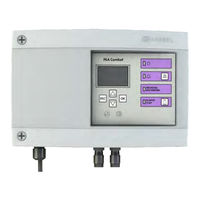
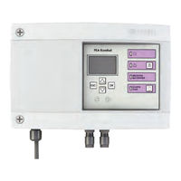
Kessel Staufix FKA Comfort Installation And Operating Manual (144 pages)
Control unit/electric components for automatic backwater valve for wastewater containing sewage
Brand: Kessel
|
Category: Control Unit
|
Size: 6 MB
Table of Contents
Advertisement
Kessel Staufix FKA Comfort Installation And Operating Manual (82 pages)
Brand: Kessel
|
Category: Control Unit
|
Size: 5 MB
Table of Contents
Kessel Staufix FKA Comfort Installation And Operating Manual (72 pages)
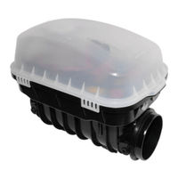
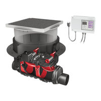
Backwater Valve for wastewater with or without raw sewage
Brand: Kessel
|
Category: Control Unit
|
Size: 15 MB
Advertisement
Kessel Staufix FKA Comfort Installation And Operating Manual (48 pages)
Backwater Valve for wastewater with or without raw sewage
Brand: Kessel
|
Category: Control Unit
|
Size: 9 MB
Table of Contents

Kessel Staufix FKA Comfort Installation And Operating Manual (16 pages)
Backwater Valve for wastewater with or without raw sewage
Brand: Kessel
|
Category: Control Unit
|
Size: 9 MB
Table of Contents
Advertisement