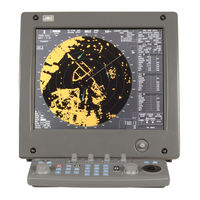
Sign In
Upload
Manuals
Brands
JRC Manuals
Marine Radar
JMA-5212-4HS/6HS
JRC JMA-5212-4HS/6HS Manuals
Manuals and User Guides for JRC JMA-5212-4HS/6HS. We have
3
JRC JMA-5212-4HS/6HS manuals available for free PDF download: User Manual, Service Manual, Installation Manual
JRC JMA-5212-4HS/6HS User Manual (494 pages)
Brand:
JRC
| Category:
Marine Radar
| Size: 5.72 MB
Table of Contents
Preface
7
Before Operation
8
Precautions
9
The Mounting Point of the Warning Label
17
Equipment Appearance
20
Table of Contents
22
Glossary
31
1 General and Equipment Composition
39
Functions
40
1.1.1 Function of this System
40
Features
41
Configuration
43
1.4 Exterior Drawings
44
1.4 Exterior Drawings
47
General System Diagrams
53
2 Screen Display and Operation Panel
57
Example of Display
58
Names and Functions of Control Panel Keys
59
Functions of Software Buttons
64
2.2 Functions of Software Buttons
65
Software Buttons for Area 1 (Top-Left Corner of the Radar Display)
65
Software Buttons for Area 2 (Bottom-Left Corner of the Radar Display)
67
Software Buttons for Area 3 (Top-Right Corner of the Radar Display)
69
Software Buttons for Area 4 (Bottom-Right Corner of the Radar Display)
71
Software Buttons for Area 5 (Own Ship Information Area) (Right Side of the Radar Display)
72
Software Buttons for Area 6 (Other Ship Information Area) (Right Side of the Radar Display)
73
Software Buttons for Area 7 (Panel Display Area) (Right Side of the Radar Display)
75
Software Buttons for Area 7 (Panel Display Area) (Right Side of the Radar Display)
76
Software Buttons for Area 8 (Operation and Message Area) (Right Side of the Radar Display)
77
3 Basic Operation
79
Flow Operation
80
Power on and Start the System
81
Observe and Adjust Video
82
Acquire and Measure Data
83
Display and Measure with Reference to CCRP
83
End the Operation and Stop the System
84
Menu Composition
85
Overview of Menu Structure
85
Basic Menu Operation
86
Preparation
88
Adjust Display Brilliance [BRILL]
88
Adjust Contrast
88
Adjust Operation Panel Brilliance [PANEL]
89
Switch Day/Night Mode [DAY/NIGHT]
89
Adjust Brilliance of Information on Radar Display (Brilliance Setting)
90
Adjust Sound Volume (Buzzer Volume)
91
Reset Alarm Buzzer [ALARM ACK]
91
Set Display Color
92
Basic Operations
94
Start Transmission [TX/PRF]
94
Stop Transmission [STBY]
94
Change Range (Observation Range Scale) [RANGE+/-]
94
Tune
95
Control Sensitivity [GAIN/PL]
96
Suppress Sea Clutter [AUTO-SEA]
97
Suppress Rain/Snow Clutter [AUTO-RAIN]
99
Reject Radar Interference [IR]
101
Hide/Display Range Rings (RINGS)
102
Hide Ship's Heading Line (HL OFF)
102
Hide Graphics Information on Radar Display (Graphic Display)
103
General Operations
104
Move Cross Cursor Mark by Trackball
104
Use Ebls (Electronic Bearing Lines) [EBL1/2]
105
Set EBL Operation (EBL1 /2 Setting)
108
Display Variable Range Markers [VRM1/VRM2]
111
Display Parallel Cursors (Parallel Cursor)
114
Display Parallel Index Lines (Parallel Index Line)
121
Switch Bearing Display Mode [AZI MODE]
128
Switch True/Relative Motion Display Mode [TM/RM]
129
Move Own Ship's Display Position [OFF CENT]
130
Display Radar Trails (Other Ships' Trails) [TRAILS]
131
Switch Pulse Length (GAIN/PL)
134
Expand Targets (Target Enhance)
135
Use Video Process (Process)
136
Zoom
137
Use Marker [MOB]
138
Marking [MARK]
139
Operate EBL Maneuver Function (EBL Maneuver)
140
Operate Multi-Function Control [MULTI]
142
Operate User Key Switches [User Key 1/2]
144
Automatic Acquisition
146
Radar Alarm (Radar Alarm)
149
Use Own Ship's Track Data (Own Track)
154
Display Own Ship's Track (Display Own Track)
154
Set Own Ship's Track Data Storage Interval (Own Track Interval)
156
Cancel Storing of Own Ship's Track Data (Own Track Memory)
157
Clear Own Ship's Track Data (Clear Own Track)
158
Display Charts
159
Insert/Remove a Card
159
Display Coastline ROM Card Produced by JRC
161
Display ERC Card
162
Fill Charts (Fill Land Area)
163
Display Navigation Information (Nav Information Display)
164
Display Waypoint Marks (Waypoint Display)
164
Display Navigation Information (NAV Display Setting)
165
Create/Edit Navigation Information (Edit User Map)
166
Set Navigation Information (User Map Setting)
172
Set and Display Geodetic System
179
Applied Operations
181
Set Radar Signal Processing (Process Setting)
181
Set Radar Trails (RADAR Trails Setting)
184
Set Cursor (Cursor Setting)
189
Set Screen(Screen Setting)
191
Screen Capture Setting
197
Set Scanner (TXRX Setting)
201
Set Chart Display (Map Setting)
203
Set LORAN C (LORAN C Correction)
215
Use Function Switch [Func]
216
Operation Procedure
216
Function Setting Menu Items
217
Overview of Function Operations
218
Overview of Stored Function Setting Data
222
Personal Information (PIN Setting)
223
Using Card
226
Save in and Transfer to Card (MEM Capa/Copy)
227
Erase/Initialize Card Memory (CLR MEM/INIT Card)
232
4 Measurement of Range and Bearing
235
Measurement Using the Cursor with the Trackball
236
Measurement by Range Rings
237
Measurement by Ebls and Vrms
238
Measurement between Two Optional Points
239
5 Operation of Tt and Ais
241
Usage of Target Tracking Function
242
Preparation
243
Collision Avoidance
244
Basic Concept of Collision Avoidance
245
Relative Vector and True Vector
246
Radar and Collision Avoidance
246
Definitions of Symbols
247
TT Data Display
252
Cursor Modes (Cursor)
254
Setting Collision Decision Criteria (CPA/TCPA Limit)
255
Setting CPA Ring (CPA Ring)
256
Setting Vectors (Vector Time)
257
Setting the GPS Antenna Location
258
Tt Operation
259
Acquiring Target [ACQ]
260
Canceling Unwanted Targets
263
Tracking Target Data Display [TGT DATA]
264
Displaying Target ID No. (Target Number Display)
266
Input of Target Information (TT Individual Setting)
267
Reference Target (Reference)
270
TT Test Menu
272
Ais Operation
278
Restrictions
278
Initial Setting
279
Setting AIS Display Function (AIS Function)
281
Activating AIS Targets (Activate AIS)
282
Deactivating AIS Targets (Deactivate AIS)
283
Displaying Numeric Data of AIS Targets (TGT DATA)
284
Displaying Target ID No. (Target Number Display)
289
Setting AIS Filter (AIS Filter Setting)
290
Conditions for Deciding AIS Target to be Lost
294
Setting AIS Alarm (AIS Alarm Setting)
295
Target Association Assessment (Association Setting)
296
Target Association Assessment
296
Priority
297
Azimuth
297
Distance
298
Course
298
Speed
299
Hysteresis
300
Non-Hysteresis
301
AIS Target to be Assessed
302
Alarm Display
303
Ais Alarm Display
308
Gyro Set Alarm
308
Track Display
309
Display Past Tracks (Past Position)
309
Other Ship's Tracks (Target Track Setting)
310
6 True and False Echoes on Display
317
Radar Wave with the Horizon
319
Strength of Reflection from the Target
321
Sea Clutter and Rain and Snow Clutter
323
False Echoes
327
Display of Radar Transponder (Sart)
330
7 Settings for System Operation
333
Settings at Installation
334
How to Open the Adjust Menu
335
Tuning Adjustment
336
Bearing Adjustment
339
Range Adjustment
340
Antenna Height Setting (Antenna Hight)
341
Setting of Ccrp/Antenna/Gps Antenna Position (CCRP Setting)
342
Navigator Setting
344
Ship Heading Equipment Setting (Heading Equipment)
347
NSK Unit Setting
348
True Bearing Value Setting (Set GYRO)
350
MAG Compass Setting
351
Ship Speed Equipment Setting (Speed Equipment)
352
Manual Speed Setting (Manual Speed)
353
Current Correction (SET/DRIFT) Setting
354
Settings
356
Communication Port Setting (COM Port Setting)
356
Baud Rate Setting
357
Reception Port Setting (RX Port)
359
Reception Sentence Setting (RX Sentence)
360
Transmission Port Setting (TX Port)
362
Sector Blank Setting (Sector Blank)
364
TNI Blank Setting (TNI Blank)
366
Bearing Pulse Output Adjustment (Output Pulse)
368
Language Setting (Language)
369
Date/Time Display Setting (Date/Time Setting)
370
Adjustment
371
Noise Level Adjustment (Noise Level)
372
Adjustment of Target Tracking Function (TT)
374
Main Bang Suppression Adjustment (MBS Level)
379
Adjustment of Performance Monitor (NJU-85)
381
Maintenance Menu
383
Scanner Safety Switch Setting (Safety Switch)
384
Initialization of Memory Area (Area Initial)
385
Save of Internal Memory Data (Card2)
387
Update of Character String Data (String Data Update)
389
Clear of Antenna Operation Time (TXRX Time CLR)
390
Update of AIS Processor Program (AIS PROC Program Update)
394
8 Maintenance and Inspection
395
Routine Maintenance
396
Maintenance on each Unit
397
8.2.1 Scanner Unit NKE-2103/2254
397
Display Unit NCD-4380
400
Performance Check
401
8.3.1 Test Menu
402
8.3.1.1 Self-Diagnosis Function
403
8.3.1.2 Monitor Test
405
8.3.1.3 Operation Panel Test
406
8.3.1.4 MON Display
408
8.3.1.5 Alarm Logging
409
8.3.1.6 System INFO
412
8.3.1.7 Magi
413
8.3.2 Line Monitor
414
GPS Reception Status Display (GPS Status)
416
Replacement of Major Parts
418
8.4.1 Parts Required for Periodic Replacement
420
8.4.2 Replacement of Magnetron
420
8.4.3 Motor Replacement
426
Replacement of Diode Limiter (A303) (JMA-5212-4/6, 5222-7/9)
432
8.4.5 Replacement of Backup Battery
433
9 Troubleshooting and After-Sales Service
435
Fault Finding
436
List of Alarms and Other Indications
436
Operation Checking
439
Fuse Checking
439
Trouble Shooting
440
Spares
441
Special Parts
443
Circuit Block to be Repaired
443
After-Sales Service
445
Keeping Period of Maintenance Parts
445
When You Request for Repair
445
Recommended Maintenance
445
Radar Failure Check List
446
10 Disposal
447
Disposal of the Unit
448
Disposal of Used Batteries
449
Disposal of Used Magnetron
450
About the China Rohs
451
11 Specifications
453
Jma-5212-4/6 Type Radar
454
Jma-5222-7/9 Type Radar
455
Scanner (Nke-2103-4/6)
456
Scanner (Nke-2254-7/9)
457
Display Unit (Ncd-4380)
458
Processor Unit (Ndc-1460)
459
Target Tracking Unit (Nca-877A)
461
Ais Unit (Nqa-2155)
462
Plotter Unit
463
Keyboard Unit (Nce-7699A)
465
Performance Monitor (Nju-85)
466
Input Enable Signal
466
Output Enable Signal
467
Standard Configuration
467
Equipment Distance between Other Instruments
468
Others (Option)
468
Advertisement
JRC JMA-5212-4HS/6HS Service Manual (172 pages)
Brand:
JRC
| Category:
Marine Radar
| Size: 4.24 MB
Table of Contents
Table of Contents
3
Chapter 1_Equipment Overview
7
Overview
9
Scanner Unit
9
Display System
10
Principal Functions
10
Chapter 2_Equipment Overview
11
Configuration
13
Scanners and Transmitted Output Powers
13
Radar Configuration and Ship's Mains
14
Power System Diagram
16
Functional System Diagram
18
Scanner Unit
18
Display System
19
Input/Output Specifications
24
Scanner (J2)
24
Gps (J3)
25
Gyro/Compass (J5)
25
Ais/Nmea (J6)
26
DIP-Sw/Jumper Setting
27
Power Circuit CBD-1702A
27
GYRO I/F Circuit CMJ-304E
29
Radar Processing Circuit CDC-1350
32
AIS Processing Circuit CDC-1353
32
T/R Control Circuit CMC-1205R
33
Chapter 3 _Service Parts
37
Service Parts Lists for the Units
37
Spare Parts
37
Special Parts
38
Nke-2103 (Jma-5212-4/6/4Hs/6Hs)
38
Nke-2254 (Jma-5222-7/9)
38
Ncd-4380
39
Exploded Diagrams
40
Nke-2103
40
Nke-2254
44
Ndc-1460
48
Nce-7699A
52
Chapter 4 _Replacement of Major Units
57
Scanner Unit
57
Precautions for Replacing Parts in the Scanner Unit
57
Parts Replacement for the Scanner Unit NKE-2254
58
Magnetron Replacement / NKE-2254
59
Motor Replacement / NKE-2254
61
Motor Drive Circuit Board Replacement / NKE-2254
63
Modulator Circuit (CPA-264) Replacement / NKE-2254
64
Power Supply Circuit Board (CBD-1682A) Replacement / NKE-2254
66
T/R Control Circuit (CMC-1205R) Replacement / NKE-2254
67
Receiver (NRG-162A) Replacement / NKE-2254
69
Encoder Replacement / NKE-2254
71
Magnetron Fan Replacement / NKE-2254
73
Modulator Fan Replacement / NKE-2254
74
NKE-2103 Scanner Unit Parts Replacement
77
Magnetron Replacement for the NKE-2103
78
Motor Replacement for the NKE-2103
80
Motor Control Power Circuit Replacement for the NKE-2103
81
Modulation Circuit (CME-363) Replacement for the NKE-2103
82
Power Circuit (CBD-1783) Replacement for the NKE-2103
83
Receiver (NRG-610) Replacement for the NKE-2103
84
Encoder Replacement for the NKE-2103
86
Display System
88
Brilliance Control Circuit CCK-970
88
Power Supply Unit NBD-866A
90
Radar Processing Circuit CDC-1350
92
Battery
94
Target Tracking (TT) Unit NCA-877A
96
AIS Processing Circuit NQA-2155
97
GYRO I/F Circuit CMJ-304E
99
GYRO I/F Circuit Fuses
101
Operation Circuit CCK-979 for the Standard Operation Unit
103
PS2 Connector Circuit CQC-1204 for the Standard Operation Unit
105
Trackball TRD-101S(BK)N1 for the Standard Operation Unit
107
Chapter 5_Program Update
109
Main Program Update Procedure
111
Items to be Provided
111
Update Procedure
111
AIS Processing Circuit Update Procedure
112
Items to be Provided
112
Update Procedure
112
How to Check the Version
113
Chapter 6_Troubleshooting
115
Operation Check
117
Self-Diagnostic Function (Self Test)
118
Display Unit Check (Monitor Test)
119
Operation Unit Check (Keyboard Test)
120
Performance Monitor (MON Display)
121
System Alarm Log Display (Alarm List/Log)
121
System Information Display (System INFO)
122
Error Message Lists
123
Error Messages for the Scanner Unit
123
Error Messages for the Display System
130
Error Messages for the External Input-Output Equipment
135
Examples of Trouble
147
Internal Circuits
147
External Equipment
149
Chapter 7_Drawings
151
Outline Drawings
153
Outline Drawing of the Scanner Unit NKE-2254-7
154
Outline Drawing of the Scanner Unit NKE-2254-9
155
Outline Drawing of the Scanner Unit NKE-2103-4/4HS
156
Outline Drawing of the Scanner Unit NKE-2103-6/6HS
157
Outline Drawing of the Display System NDC-1460
158
Outline Drawing of the Display Unit NWZ-164
159
Outline Drawing of the Operation Unit NCE-7699A
160
Outline Drawing of the Multi-Function Operation Unit NCE-7729A
161
Outline Drawing of the Rectifier NBA-5111 (Option)
162
System Diagrams
163
Overall System Diagram of the Radar JMA-5222-7/9
163
Overall System Diagram of the Radar JMA-5212-4/6/4HS/6HS
164
Inter-Unit Connection Diagram
165
Inter-Unit Connection Diagram of the JMA-5222-7/9
165
Inter-Unit Connection Diagram of the JMA-5212-4/6/4HS/6HS
166
Unit Internal Connection Diagrams
167
Internal Connection Diagram of the Scanner Unit NKE-2254
167
Internal Connection Diagram of the Scanner Unit NKE-2103
168
Internal Connection Diagram of the Processor Unit NDC-1460
169
JRC JMA-5212-4HS/6HS Installation Manual (156 pages)
MARINE RADAR EQUIPMENT
Brand:
JRC
| Category:
Marine Radar
| Size: 3.32 MB
Table of Contents
Table of Contents
3
1 Overview
11
2 Installation of the Scanner
11
Selecting the Installation Position
12
Installation Procedure
16
Connecting the Installation Cable (Nke-2103)
20
Connecting the Installation Cable (Nke-2254)
22
3 Installation of the Display Unit
25
Selecting the Installation Position
26
Installation of the Lcd Monitor
27
Installation of the Operation Unit
29
Installation of the Power Cable (Cfq-5436)
30
Installation of the Cable (Cfq-6912) between the Radar Process Unit and the Scanner
33
Connecting to the Gps Receiver
35
Connecting to the Gps Compass
40
Connecting to Nmea Heading Output Device
48
Connecting to the Gyro and Electromagnetic Log (Nsk Unit Setting) (Option)
50
Connecting to the Pc Plotter
56
Connecting to Other Nmea Devices
57
Connection with Other Devices (Sub Indicator Output and Slave Input)
59
Connection with Other Devices
59
Power Supply (Nba-5111) (Option)
63
Target Tracking (Nca-877A) (Option)
64
Plotter Circuit (Ndb-44) (Option)
66
Connecting to Ais (Nqa-2155) (Option)
68
Coastline Rom Card/Memory Card
72
Connect Slave Monitor / Vdr
75
Simplified Inter-Switch Installation
77
Sub Key-Board Installation
79
Connecting to External Buzzers
81
Connecting Contact Signals to External Devices
83
4 Initial Setting
85
How to Open the Equipment Setup Menu
86
Tune Adjustment
87
Bearing Adjustment
90
Range Adjustment
91
Setting of True Bearing Value
92
Antenna Height Setting (Antenna Height)
93
Setting of Ccrp/Antenna/Gps Antenna Position (Ccrp Setting)
94
Communication Port Setting (Com Port Setting)
96
Sector Blank Setting (Sector Blank)
102
Tni Blank Setting (Tni Blank)
104
Setting of Pulse Output Selection (Bearing Pulses from Antenna)
105
Setting of Pulse Output Selection
105
(Bearing Pulses from Antenna)
105
Language Setting (Language)
106
Date Time Setting
107
Main Bang Suppression Adjustment (Mbs)
108
Adjustment of Performance Monitor (Mon)
110
Magnet Compass Setting
112
Gps Receiver Setting
113
Dgps Receiver Setting
122
Sbas Receiver Setting
126
Displaying Gps Reception Status
131
Simplifedinter-Switch Settings
133
5 Measures against Noise Interference in the Radio Equipment
135
Shield of Devices
136
Inter-Unit Cables
136
Installation Location
136
Grounding
136
Advertisement
Advertisement
Related Products
JRC JMA-5212-4/6
JRC JMA-5210-4
JRC JMA-5210-6
JRC JMA-5212-4
JRC JMA-5212-6
JRC JMA-5212-4HS
JRC JMA-5212-8HS
JRC JMA-5212-6HS
JRC JMA-5206
JRC JMA-5222-7
JRC Categories
Water Filtration Systems
Marine Radar
Marine Equipment
Radio Parts
Receiver
More JRC Manuals
Login
Sign In
OR
Sign in with Facebook
Sign in with Google
Upload manual
Upload from disk
Upload from URL