Sign In
Upload
Manuals
Brands
IEI Technology Manuals
Single board computers
SPCIE-3600AM2
IEI Technology SPCIE-3600AM2 Manuals
Manuals and User Guides for IEI Technology SPCIE-3600AM2. We have
1
IEI Technology SPCIE-3600AM2 manual available for free PDF download: User Manual
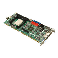
IEI Technology SPCIE-3600AM2 User Manual (215 pages)
Full-size AMD Socket AM2 PICMG 1.3 CPU Card supports Opteron, Athlon 64 x2, Athlon 64 and Sempron processors, 28 PCIe Expansion Lanes, Dual GbE, Six SATA 2.0, Ten USB 2.0 and CRT Output
Brand:
IEI Technology
| Category:
Single board computers
| Size: 4.73 MB
Table of Contents
Table of Contents
7
1 Introduction
21
Figure 1-1: SPCIE-3600AM2 PICMG 1.3 CPU Card
22
Figure 1-2: SPCIE-3600AM2 Overview [Front View]
24
Technical Specifications
25
Overview
22
SPCIE-3600AM2 Expansion Options
22
PCI Express (Pcie) Expansion
22
SPCIE-3600AM2 Features
23
PCI Expansion
23
USB 2.0 Expansion
23
Spcie-3600Am2 Overview
24
SPCIE-3600AM2 Overview Photo
24
SPCIE-3600AM2 Peripheral Connectors and Jumpers
24
Table 1-1: Technical Specifications
26
2 Detailed Specifications
27
Dimensions
28
Board Dimensions
28
Figure 2-1: SPCIE-3600AM2 Dimensions (MM)
28
Figure 2-2: External Interface Panel Dimensions (MM)
29
Figure 2-3: Data Flow Block Diagram
30
L1 and L2 Cache
31
Processor Features
31
Table 2-1: Technical Specifications
31
DDR2 Memory Controller
32
Figure 2-4: DIMM Sockets
32
Processor Power Management
32
Figure 2-5: Hypertransport™ Technology Link
33
Hypertransport™ Link
33
Hypertransport™ Technology
33
NVIDIA Mcp55Pro
33
PCI Express Interface
34
Pcie Express Overview
34
Pcie X16 Expansion
34
Pcie X1 Edge Connector
35
Pcie X8 Expansion Connector
35
Compatible Processors
30
Supported Processors
30
Data Flow
29
External Interface Panel Dimensions
29
Figure 2-6: Pcie X16 Edge Connector
35
Figure 2-8: Pcie X8 Expansion Connector
36
Figure 2-9: Graphics Controller and VGA Connector
37
Figure 2-10: 40-Pin IDE Connector
39
PCI Host Bus Controller
39
Figure 2-11: PCI Bus Edge Connector
40
SATA Controllers
40
Figure 2-12: SATA II Connectors
41
USB Controllers
41
Figure 2-13: USB Connectors and USB Edge Connector
42
Gigabit Ethernet Connector
42
Figure 2-14: LAN Connectivity
43
LPC Bus
43
Smbus Controller
43
DMA Controller
44
HD Audio
44
Interrupt Controller
44
Figure 2-15: LPC BUS Components
45
Lpc Bus Components
45
LPC Bus Overview
45
Timer and RTC (Real Time Clock)
45
BIOS Chipset
46
Super I/O LPC Interface
46
Winbond W83627EHG Super I/O Chipset
46
Super I/O Hardware Monitor Functions
47
Super I/O Keyboard and Mouse Controller
47
Super I/O UART Controller
47
Environmental and Power Specifications
48
Super I/O Fan Speed and Fan Control
48
System Monitoring
48
Operating Temperature and Temperature Control
49
Power Consumption
49
Table 2-2: Power Consumption
49
Expansion Options
50
Expansion Options Overview
50
IEI Expansion PICMG 1.3 Backplanes
50
IEI Chassis
51
Figure 2-7: Pcie X1 Edge Connector
35
High Performance 2D Accelerator
37
Resolution, Color and Frame Rate
37
IDE Interface Controller
38
XGI Volari™ Z9S Graphics Chipset
36
Graphics Chipset Overview
36
Table 2-3: Compatible IEI PICMG 1.3 Backplanes
51
Figure 2-15: Pcie X8 Board-To-Board Connector
51
Table 2-4: Compatible IEI Chassis
52
3 Unpacking
53
Anti-Static Precautions
54
Unpacking
54
Unpacking Precautions
54
Unpacking Checklist
55
Package Contents
55
Table 3-1: Package List Contents
56
Optional Items
57
Table 3-2: Package List Contents
57
4 Connector Pinouts
59
Figure 4-1: Connector and Jumper Locations
60
Peripheral Interface Connectors
60
SPCIE-3600AM2 Layout
60
External Interface Panel Connectors
61
Table 4-2: Rear Panel Connectors
61
Table 4-1: Peripheral Interface Connectors
61
Internal Peripheral Connectors
62
ATX Power Supply Enable Connector
62
Audio Connector
63
Figure 4-2: ATX Power Supply Enable Connector Location
63
Figure 4-3: Audio Connector Location (9-Pin)
64
Figure 4-4: +12V Fan Connector Location
65
Fan Connector (+12V, 3-Pin)
66
Table 4-3: ATX Power Supply Enable Connector Pinouts
63
Table 4-4: Audio Connector Pinouts
64
Cooling Fan Connector (+12V, 4-Pin)
65
Table 4-5: +12V Fan Connector Pinouts
66
Figure 4-5: +12V Fan Connector Location
67
Table 4-6: +12V Fan Connector Pinouts
67
Table 4-7: Front Panel Connector Pinouts (14-Pin)
69
Figure 4-7: IDE Device Connector Locations
70
Keyboard Connector
71
Table 4-8: IDE Connector Pinouts
71
Figure 4-9: Mouse Connector Location
73
Table 4-10: Mouse Connector Pinouts
73
Figure 4-10: SATA Drive Connector Locations
74
SATA Drive Connectors
74
Serial Port Connector (COM1, COM 2)
75
Table 4-11: SATA Drive Connector Pinouts
75
Figure 4-11: Serial Connector Pinout Locations
76
Table 4-12: Serial Connector Pinouts
76
Trusted Platform Module (TPM) Connector
76
Figure 4-12: TPM Connector Pinout Locations
77
Table 4-13: TPM Connector Pinouts
78
USB Connectors (Internal)
78
Figure 4-13: USB Connector Pinout Locations
79
Table 4-14: USB Port Connector Pinouts
79
External Peripheral Interface Connector Panel
80
Figure 4-14: SPCIE-3600AM2 External Peripheral Interface Connector
80
LAN Connectors
80
Figure 4-15: RJ-45 Ethernet Connector
81
Table 4-15: LAN Pinouts
81
Table 4-16: RJ-45 Ethernet Connector Leds
81
USB Connector
81
VGA Connector
82
Figure 4-8: Keyboard Connector Location
72
Mouse Connector
72
Table 4-9: Keyboard Connector Pinouts
72
Figure 4-6: Front Panel Connector Pinout Locations (14-Pin)
68
Front Panel Connector (14-Pin)
68
IDE Connector (40-Pin)
69
Figure 4-16: VGA Connector
82
Table 4-17: USB Port Pinouts
82
Table 4-18: VGA Connector Pinouts
83
5 Installation
85
Anti-Static Precautions
86
Installation Considerations
87
Installation Notices
87
Installation Checklist
88
Unpacking
89
Unpacking Precautions
89
Cpu, Cpu Cooling Kit and DIMM Installation
90
Socket AM2 CPU Installation
90
Figure 5-1: Install the CPU
91
Figure 5-3: Install the CPU Cooler
93
Table 5-1: Jumpers
95
Table 5-2: Clear CMOS Jumper Settings
96
Airflow
97
Chassis Installation
97
Backplane Installation
98
CPU Card Installation
98
ATA Flat Cable Connection
99
Internal Peripheral Device Connections
99
Peripheral Device Cables
99
Table 5-3: IEI Provided Cables
99
Audio Kit Installation
100
Keyboard and Mouse PS/2 Cable with Bracket
101
Figure 5-8: Keyboard and Mouse PS/2 Cable with Bracket
102
Dual RS-232 Cable Connection
103
Figure 5-9: PS/2 Connector
103
Figure 5-10: Dual RS-232 Cable Installation
104
SATA Drive Connection
104
Figure 5-4: Installing a DIMM
94
Jumper Settings
95
Clear CMOS Jumper
95
Figure 5-2: IEI Cooling Kit
92
Socket AM2 Cooling Kit Installation
92
DIMM Installation
93
Figure 5-12: SATA Power Drive Connection
105
Figure 5-14: LAN Connection
108
Figure 5-15: USB Device Connection
109
Figure 5-16: VGA Connector
110
Connecting the Pcie X8 Connector to the Backplane
111
VGA Monitor Connection
109
Connecting the Spcie-3600Am2 to the Backplane
110
Installing the SPCIE-3600AM2 Onto the Backplane
110
Figure 5-11: SATA Drive Cable Connection
105
Figure 5-13: Dual USB Cable Connection
106
USB Cable (Dual Port)
106
External Peripheral Interface Connection
107
LAN Connection (Single Connector)
107
USB Device Connection (Single Connector)
108
Figure 5-17: SPCIE-3600AM2 Installation
111
Figure 5-18: Pcie X8 Board-To-Board Connector Installation
112
6 Bios Screens
113
Introduction
114
Starting Setup
114
Using Setup
114
Getting Help
115
Unable to Reboot after Configuration Changes
115
BIOS Menu Bar
115
Main
116
Advanced
117
CPU Configuration
118
IDE Configuration
120
IDE Master, IDE Slave and Serial-ATA Primary/Secondary Channel
124
Super IO Configuration
129
Hardware Health Configuration
131
SMART FAN Control Configuration
133
ACPI Configuration
135
APM Configuration
136
Remote Access Configuration
138
Trusted Computing
142
USB Configuration
143
Pci/Pnp
145
Boot
147
Boot Settings Configuration
148
Boot Device Priority
150
Security
151
Chipset
153
Northbridge Chipset Configuration
154
Southbridge/Mcp55 Configuration
155
Exit
157
7 Raid Setup
159
Introduction
160
Precautions
160
Features and Benefits
161
Setting up the Raid
161
Figure 7-1: NVIDIA RAID Setup
162
Figure 7-2: RAID Setup Utility
163
Raid Tool Access
164
8 Software Drivers
165
Available Software Drivers
166
Driver CD Auto-Run
166
Figure 8-2: Available Drivers
167
Figure 8-1: Introduction Screen
167
Chipset Driver Installation
168
Figure 8-3: Select os for Chipset Driver Installation
168
Figure 8-4: Operating System Type
169
Figure 8-5: Chipset Driver Revision Directory Icon
169
Figure 8-7: Chipset Driver Installation License Agreement
170
Figure 8-6: Chipset Driver Setup Icon
170
Figure 8-9: Welcome Screen
171
Figure 8-8: Chipset Driver Folder Selection
171
Figure 8-10: Chipset Driver Installation Complete
172
Figure 8-11: XGI Directory Icon
172
Xgi Vga Driver Installation
172
Figure 8-13: VGA Driver Revision Directory Icon
173
Figure 8-12: System Icon
173
Figure 8-15: Preparing VGA Driver Setup
174
Figure 8-14: XGI VGA Driver Setup Icon
174
Figure 8-17: Windows Logo Testing
175
Figure 8-16: VGA Driver Welcome Screen
175
Hd Audio Kit Driver Installation
176
BIOS Setup
176
Driver Installation
176
Figure 8-18: VGA Driver Installation Complete Screen
176
Figure 8-19: Select the Audio CODEC
177
Figure 8-20: Driver Directory
177
Figure 8-21: Select Operating System Type
178
Figure 8-22: Operating System
178
Figure 8-23: Locate the Setup Program Icon
179
Figure 8-24: Preparing Setup Screen
179
Figure 8-25: Installshield Wizard Welcome Screen
180
Figure 8-26: Audio Driver Software Configuration
180
Figure 8-27: Restart the Computer
181
Abios Options
183
Bterminology
187
Cwatchdog Timer
191
Daddress Mapping
195
Address Map
196
St Mb Memory Ddress Ap
196
Irq Mapping Table
197
Dma Channel Assignments
197
Ecompatibility
199
Compatible Operating Systems
200
Compatible Processors
200
Compatible Memory Modules
201
Hazardous Materials Disclosure
203
Hazardous Material Disclosure Table for IPB Products Certified as Rohs Compliant under 2002/95/EC Without Mercury
204
Graid Levels
207
Introduction
208
RAID 0 or Disk Striping
208
RAID 1 or Disk Mirroring
208
RAID 10 or Disk Mirroring and Striping
208
Raid 5
209
Jbod
209
Index
211
Advertisement
Advertisement
Related Products
IEI Technology SPCIE-C236
IEI Technology SPCIE-C2260-i2
IEI Technology SPCIE-C236-R10
IEI Technology SPCIE-C236-i2-R10
IEI Technology SPCIE-C2260-i2-R10
IEI Technology SPCIE-C246
IEI Technology SPCIE-C2260
IEI Technology SPCIE-C2060
IEI Technology SPCIE-C2160
IEI Technology S19A-QM87
IEI Technology Categories
Motherboard
Touch Panel
Computer Hardware
Single board computers
Desktop
More IEI Technology Manuals
Login
Sign In
OR
Sign in with Facebook
Sign in with Google
Upload manual
Upload from disk
Upload from URL