Sign In
Upload
Manuals
Brands
Fujitsu Manuals
Motherboard
F2MC-8FX Series
Fujitsu F2MC-8FX Series Manuals
Manuals and User Guides for Fujitsu F2MC-8FX Series. We have
14
Fujitsu F2MC-8FX Series manuals available for free PDF download: User Manual, Application Note, Setup Manual, Operation Manual
Fujitsu F2MC-8FX Series User Manual (110 pages)
8-BIT MICROCONTROLLER bits pot yellow LIN board
Brand:
Fujitsu
| Category:
Microcontrollers
| Size: 2.26 MB
Table of Contents
Revision History
2
Note
3
Table of Contents
4
Introduction
10
Contact
11
Suppliers of the Parts/Materials
12
1 Setting up the Starter Kit
13
Table 1-1 Component List
13
Figure 1-1 External View of a Starter Kit
14
Table 1-2 Description of the Respective Parts of a Starter Kit
15
Figure 1-2 System Connection Diagram (Single-Unit Operation)
17
Figure 1-3 System Connection Diagram (When Performing LIN Communication)
18
Table 1-3 MB95F136JBS Pin Assignment
19
Setting up the PC
21
Downloading the Software
22
Installing the Integrated Development Environment SOFTUNE (Bits Pot Yellow Dedicated Version)
22
Figure 1-4 SOFTUNE Setup Confirmation
22
Figure 1-5 Starting SOFTUNE Setup
22
Figure 1-6 SOFTUNE Setup Confirmation
23
Figure 1-7 SOFTUNE Setup/License Agreement
23
Figure 1-8 SOFTUNE Setup/Version Information
24
Figure 1-9 SOFTUNE Setup/Selecting the Destination of Installation
24
Figure 1-10 SOFTUNE Setup/Selecting the Components
25
Figure 1-11 SOFTUNE Setup/Confirming the Installation Settings
25
Figure 1-12 SOFTUNE Setup/Completion
26
Installing the PC Writer FUJITSU FLASH USB Programmer (Bits Pot Yellow Dedicated Version)
27
Figure 1-13 PC Writer/Installation Dialog
27
Figure 1-14 PC Writer/Setup Type
28
Figure 1-15 Finished PC Writer/Ready to Install
28
Figure 1-16 Completing the PC Writer Installation
29
Connecting It to the PC and Installing the USB Driver
30
Figure 1-17 Installing BGM Adapter (MB2146-09)
30
Figure 1-18 Selecting the Search Locations
31
Figure 1-19 Hardware Installation
31
Figure 1-20 Completing the BGM Adapter (MB2146-09) Installation
32
Configuring the Starter Kit
33
Figure 1-21 MODE Selection
33
Figure 1-22 Connection between the PC and the Starter Kit
34
2 Running the Program
35
Executing in Single Chip Mode
36
Building a Project
36
Figure 2-1 SOFTUNE Workbench Start Window
36
Figure 2-2 Opening a Workspace
37
Figure 2-3 Selecting a Workspace
37
Figure 2-4 Setting the Active Project
38
Figure 2-5 Changing the Active Project
38
Figure 2-6 Building a Project
39
Figure 2-7 Completing the Build
39
Writing the Program into the Microcontroller
40
Figure 2-8 Opening the File to Write
40
Figure 2-9 Selecting the File to Write
41
Figure 2-10 Writing the Program
41
Figure 2-11 Completing the Program Writing
42
Debugging by Using Monitor Debugger
43
Activating SOFTUNE and Configuring the Debug Settings
43
Figure 2-12 Opening a Workspace
43
Figure 2-13 Selecting a Workspace
44
Figure 2-14 Building a Project
45
Figure 2-15 Completing the Build
45
Figure 2-16 Load Module Outputs
46
Figure 2-17 Debug Settings
47
Figure 2-18 Changing the Debug Settings
47
Figure 2-19 Starting the Debug Setting Wizard
48
Figure 2-20 Selecting the Debugger Type
48
Figure 2-21 Entering Password When Starting Debugger
49
Figure 2-22 Selecting the Device Type
49
Figure 2-23 Setting the Primary Oscillation Frequency
50
Figure 2-24 Specifying a Batch File
50
Figure 2-25 Configuring the Target File Settings
51
Figure 2-26 Setting Setup File Selection
51
Figure 2-27 Completing the Setup Wizard
52
Figure 2-28 Completing the Project Settings
52
Writing the Monitor Program into the Microcontroller
53
Figure 2-29 Opening the File to Write
53
Figure 2-30 Selecting the File to Write
54
Figure 2-31 Writing the Program
55
Figure 2-32 Completing the Program Writing
55
Loading the Target File
56
Figure 2-33 Start Debugging
56
Running the Debugger
57
Figure 2-34 Setting Break Points
57
Figure 2-35 Running the Program
58
Figure 2-36 Stopping the Program
58
3 Operation of the Sample Programs
60
Bits Pot Yellow Single-Unit Operation
61
Figure 3-1 Single-Unit Operation/Controls and Mechanicals
61
Table 3-1 Single-Unit Operation/Descriptions of the Controls and Mechanicals
62
LIN Communication Operation (LIN Communication Operation with the Bits Pot White)
63
Figure 3-2 LIN Communication Operation/Controls and Mechanicals
63
Table 3-2 LIN Communication/Descriptions of the Controls and Mechanicals
64
4 Try to Operate the Bits Pot Yellow (Single-Unit)
65
Overview of Single-Unit Operation
65
Turning on Leds Using Switch Operations
65
Figure 4-1 Single-Unit Operation/Switches and Leds
65
Figure 4-2 LED Lighting Circuit
66
Figure 4-3 LED ON/OFF Circuit Example (Schematic Diagram)
66
Figure 4-4 Connection Configuration between SW2 and Microcontroller Pins (Schematic Diagram)
67
Controlling the Buzzer Using the Volume Switch
69
Figure 4-5 Single-Unit Operation/Volume SW
69
Figure 4-6 Volume SW (Variable Resistor)
69
Figure 4-7 Circuit Surrounding the Voltage Adjustment Knob
70
Figure 4-8 Piezoelectricity
71
Figure 4-9 Principle of Piezoelectric Elements
72
LED Displays Using Temperature Sensor Operations
73
Figure 4-10 Peripheral Circuit Diagram for Temperature Sensor
73
Understanding and Running the Program in Single-Unit Operation
74
Figure 4-11 Single-Unit Operation Flowcharts
74
Figure 4-12 Operation Mode Settings (When Using Volume Switch)
75
Figure 4-13 Operation Mode Settings (When Using the Temperature Sensor)
75
Figure 4-14 Main Function Program
76
Figure 4-15 SW2 Interrupts (LED On/Off Processing)
77
Figure 4-16 SW3 Interrupts (Buzzer Output Processing)
77
Figure 4-17 A/D Converter Interrupts
78
5 Try to Use LIN Communication
79
What Is LIN
79
Figure 5-1 Example of Vehicle LIN Applications
80
Figure 5-2 Main LIN Network Configuration
81
LIN Specifications
82
Lin Frame Configuration
82
Figure 5-3 LIN Communication Flow
83
Figure 5-4 LIN Frame Configuration
83
LIN Communication Flow
85
Figure 5-5 Main LIN Network Configuration
86
Figure 5-6 Example of Communication Sequence between the Master and Slaves During Normal
86
Communication between Master and Slave if an Error Occurs
87
LIN Communication by Using Microcontroller
88
Figure 5-7 LIN Circuit
88
Figure 5-8 Entire LIN Communication Control Registers
89
Table 5-1 Description of the Entire LIN Communication Control Registers and Setting Values
90
Understanding and Overview of the Program for LIN Communication
92
LIN Communication Configuration
92
Table 5-2 LIN Communication Conditions of the Sample Program
92
Table 5-3 LIN Message Ids in the Sample Program
92
Sample Programs Sequence
97
Figure 5-9 LIN Communication Flowchart (Main Routine)
97
Figure 5-10 LIN Communication Flowchart (Interrupt Routine: UART Reception Interrupts)
98
Figure 5-11 LIN Communication Flowchart (Interrupt Routine: Input Capture Interrupts)
98
Figure 5-12 Operations Points of Interrupt Processes
99
Figure 5-13 Synch Break Interrupt Control
100
Figure 5-14 Input Capture Operation in the Synch Field
101
Figure 5-15 Input Capture (ICU) Interrupt Controls
102
Figure 5-16 LIN-UART Receive Interrupt Control
103
Figure 5-17 Receive Determination Processing
103
Figure 5-18 Timeout Detection Processing
105
Figure 5-19 Data Send Processing
106
Figure 5-20 Data Reception Processing
107
Figure 5-21 Submain Processing
108
6 Appendix
109
Sample Program Folder/File Configuration
109
Table 6-1 Sample Program Folder/File Configuration
109
Advertisement
Fujitsu F2MC-8FX Series Application Note (53 pages)
Brand:
Fujitsu
| Category:
Motherboard
| Size: 1.27 MB
Table of Contents
Application Note
1
Revision History
2
Contents
3
Table of Contents
3
1 Product Overview
6
Objective and Deliverable
6
System Block
6
Handling Precautions
6
Feature
7
Hardware Setup
7
2 Bgma Manual
8
BGMA Overview
8
Function List
8
IDC10 Interface Description
9
BGMA USB Configuration
9
LED Description
12
3 Ev-Board Manual
13
EV-Board Overview
13
Function List
14
EV-Board Schematic
15
HW Module Description and Jumper Settings
16
Pin Assignment of MB95350L
16
Power Module
17
I2C Slave Module
18
I2C Master Module
18
A/D Module
19
LED Module
20
Operation Manual
21
Single Board Mode
21
Series Connection Mode
22
Net Connection Mode
23
ADC Module
24
Wake-Up Operation
24
Reset Operation
25
Test Pin
25
Battery Usage
25
4 Sample Code Manual
26
Project Structure
26
Source Code File Description
27
ADC .C
27
Addressjudge .C
28
Ext-Interrupt .C
29
I2C .C
30
Initial .C
31
Slavemodei2C .C
32
Standby .C
33
Timer.C
34
API Code File Description
35
I2Cmastermacro.C
35
I2Cslavemacro.C
37
Sleepmacro.C
38
Global Variable Description
39
How to Add These Files
40
Usage Demo
41
Code of Main.C
41
Code of Initial_Adc
41
Code of Read_Adc
42
Code of Judge_Slaveaddr
42
Code of Init_Ext
43
Code of INTER_EXT
43
Code of I2C_Init
43
Code of Read_I2C
44
Code of Write_I2C
44
Code of Initial
44
Code of Slavei2C_Prepareforinter
45
Code of Inter_I2Cslavemodewakeup
46
Code of STBLED_ON
47
Code of Write_Standby
47
Code of Clock_Init
47
Code of Judge_P00
48
Code of Ledcoordin
48
Code of EEPROM_I2C
49
Code of Enddevice_I2C
49
Code of I2C_Mastermacro
50
Code of I2C_Slavemacro
50
Code of Sleep_Macro
50
5 Development Platform Quick Start
51
Tools Setup Sequence
51
Open Project and Start Debug
51
Operation Precautions
51
6 Additional Information
52
7 Appendix
53
Tables
53
Figures
53
Fujitsu F2MC-8FX Series User Manual (24 pages)
8-BIT MICROCONTROLLER
Brand:
Fujitsu
| Category:
Microcontrollers
| Size: 0.3 MB
Table of Contents
Revision History
2
Table of Contents
3
Contents
3
1 Introduction
5
2 System Hardware Environment
6
3 Development Environment and Tools
7
4 Hardware Design
8
System Hardware Block Diagram
8
MCU Resource Usage
8
MCU Pin Assignment
9
5 System Function
10
Global Variable
10
Function List
10
Function Prototype
10
Initsys ()
10
Getkey ()
10
Parsekey ()
10
Eventproc ()
10
Display ()
11
6 Event Function
12
Function List
12
Function Prototype
12
Modecaocai ()
12
Modehuoguo ()
12
Modeduncai ()
12
Modebaotang ()
13
Modebaowen ()
13
Wattinc ()
13
Wattdec ()
13
Tmrinc ()
13
Tmrdec ()
13
Tmrrst ()
13
Tempinc ()
14
Tempdec ()
14
Consttempproc ()
14
7 Driver Function
15
Function List
15
Function Prototype
15
Getadc (Int Chl)
15
Buzzeron ()
15
Buzzeroff ()
15
Poweron ()
16
Poweroff ()
16
Pwmset (Int Cycle,Int Duty)
16
Pwmon ()
16
Pwmoff ()
16
Fanon ()
16
Fanoff ()
16
Vcinit ()
17
Opampinit ()
17
8 Interrupt Function
18
Function List
18
Function Prototype
18
Keyboard ()
18
Protectigbt ()
18
Protectsys ()
18
Intcurover ()
18
Intvolover ()
19
Intsurge ()
19
Intkettle ()
19
9 Demo System
20
System Features
20
Software Design
21
User Interface
21
System Module
21
System Main Loop
22
System Files
22
System Files Structure
23
Appendix
24
Advertisement
Fujitsu F2MC-8FX Series Setup Manual (23 pages)
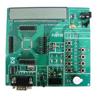
F2MC-8FX FAMILY MB95330 SERIES 8-BIT MICROCONTROLLER EV BOARD
Brand:
Fujitsu
| Category:
Motherboard
| Size: 0.81 MB
Table of Contents
Preface
3
Handling and Use
3
Notice on this Document
3
Revision History
4
Caution of the Products Described in this Document
4
Table of Contents
6
Contents
6
Bgma Manual
7
BGMA Overview
7
Function List
7
IDC10 Interface Description
8
BGMA USB Configuration
8
LED Description
10
Ev Board Introduction
12
EV Board Overview
12
Function List
13
EV Board Schematic
14
HW Module Description
15
Power Module
15
BGMA Interface
15
Key Module
15
Speed Module
15
LED Module
16
Feedback Module
16
Motor Drive Module
17
Ev Board Operation
18
Connect the Motor Connector and the Hall Sensor Connector
18
Select the Driving Method as Hall Sensor or Back EMF
18
Start and Stop Motor
19
Adjust Motor Speed
20
Reverse Motor Rotation
20
Development Platform Quick Start
21
Tools Setup Sequence
21
Open Project and Start Debug
21
Fujitsu F2MC-8FX Series Application Note (23 pages)
EMULATOR HW SETUP
Brand:
Fujitsu
| Category:
Microcontrollers
| Size: 4.41 MB
Table of Contents
Revision History
2
Warranty and Disclaimer
3
Contents
4
Table of Contents
4
1 Introduction
5
2 Hardware Requirements
6
Devices
6
3 Setting up the Emulation System
7
System Configuration
7
BGM Adapter
8
Connection to the Host Machine
8
Connection to the User System
8
Adapter Interface Specifications
9
Tool Reset Specifications
9
MCU Board
10
Connecting the MCU Board to the Evaluation Board
10
Jumper Settings and Switches on MCU Board
11
How to Mount Oscillator on MCU Board
12
Evaluation Board
13
Jumper Settings on Evaluation Board
13
4 Setting up the Emulation Software
14
Download Monitor Program
14
Making Setup File by Setup Wizard for Emulator
14
Procedure for Setting Setup File by Setup Wizard
14
Optimization of Response Speed During Debugging
19
Executing Program
20
Run Program
20
Setting Breakpoints
21
Types of Breakpoints and How to Set
22
Trace Windows
22
Display Format for Trace Data
23
Saving Setup File for the Emulator
23
Fujitsu F2MC-8FX Series Setup Manual (19 pages)
8-BIT, EV Board
Brand:
Fujitsu
| Category:
Microcontrollers
| Size: 0.74 MB
Table of Contents
Revision History
2
Contents
3
Table of Contents
3
1 Bgma Manual
4
BGMA Overview
4
Function List
4
IDC10 Interface Description
5
BGMA USB Configuration
5
LED Description
7
2 Ev Board Introduction
9
EV Board Overview
9
Function List
10
EV Board Schematic
11
HW Module Description
12
Power Module
12
BGMA Interface
12
Key Module
12
Speed Module
12
LED Module
13
Feedback Module
13
Motor Drive Module
13
3 Ev Board Operation
14
Connect the Motor Connector and the Hall Sensor Connector
14
Select the Driving Method as Hall Sensor or Back EMF
14
Start and Stop Motor
15
Adjust Motor Speed
16
Reverse Motor Rotation
16
4 Development Platform Quick Start
17
Tools Setup Sequence
17
Open Project and Start Debug
17
5 Additional Information
18
6 Appendix
19
Fujitsu F2MC-8FX Series Setup Manual (18 pages)
Brand:
Fujitsu
| Category:
Motherboard
| Size: 0.84 MB
Table of Contents
Preface
3
Handling and Use
3
Notice on this Document
3
Revision History
4
Caution of the Products Described in this Document
4
Table of Contents
6
Contents
6
1 Bgma Manual
7
BGMA Overview
7
Function List
7
IDC10 Interface Description
8
BGMA USB Configuration
8
LED Description
10
2 Ev Board Introduction
12
EV Board Overview
12
Function List
13
EV Board Schematic
14
HW Module Description
15
Power Module
15
BGMA Interface
15
Test Pin
15
Connector
15
3 Development Platform Quick Start
16
Tools Setup Sequence
16
Open Project and Start Debug
16
Fujitsu F2MC-8FX Series Application Note (21 pages)
Adapter
Brand:
Fujitsu
| Category:
Microcontrollers
| Size: 2.24 MB
Table of Contents
Revision History
2
Table of Contents
3
1 Introduction
4
2 Application Environment
5
Mother Board
5
Debug Tool
5
Softune
6
USB Programmer
6
3 Hardware Connection
7
Independent Usage
7
Used with Mother Board
9
4 Program Function
12
Use MB95310 Series USB Programmer to Program
12
Use FMC-8L/8FX SOFTUNE to Program
12
5 Schematic
17
LQFP80 PGM Adaptor
17
6 Pn Definition Rule
18
7 Pn List of Applicable Mcus
19
8 More Information
20
9 Appendix
21
Fujitsu F2MC-8FX Series Application Note (20 pages)
8-BIT MICROCONTROLLER
Brand:
Fujitsu
| Category:
Microcontrollers
| Size: 1.32 MB
Table of Contents
Revision History
2
Table of Contents
3
Contents
2
1 Introduction
4
2 Application Environment
5
TSC Demo Platform
5
TSC Tuning Platform
6
3 Tsc Demo Functions
7
Demo System Build-Up
7
IDC 10 Pin Assignment
7
Demo System Power-On
8
APIS (Adjacent Pattern Interference Suppression) Modes
9
Demo Functions
13
Waterproof Key Pad
14
4 Tsc Tuning
15
Tuning Interface
15
Tuning System Build-Up
17
5 Demo Firmware
18
6 Additional Information
19
7 Appendix
20
Fujitsu F2MC-8FX Series Setup Manual (17 pages)
8-BIT MICROCONTROLLER
Brand:
Fujitsu
| Category:
Motherboard
| Size: 0.66 MB
Table of Contents
Revision History
4
Table of Contents
5
Contents
5
1 Bgma Manual
6
BGMA Overview
6
Function List
6
IDC10 Interface Description
7
BGMA USB Configuration
7
LED Description
9
2 Ev Board Introduction
11
EV Board Overview
11
Function List
12
EV Board Schematic
13
HW Module Description
14
Power Module
14
BGMA Interface
14
Test Pin
14
Connector
14
3 Development Platform Quick Start
15
Tools Setup Sequence
15
Open Project and Start Debug
15
4 Additional Information
16
5 Appendix
17
Fujitsu F2MC-8FX Series Setup Manual (30 pages)
STARTER KIT (ver. 3V)
Brand:
Fujitsu
| Category:
Semiconductors
| Size: 1.34 MB
Table of Contents
Handling Precautions
6
Hardware Setup
7
Software Setup
14
Installation of Software
14
Fujitsu F2MC-8FX Series Operation Manual (20 pages)
MCU BOARD for MB95FV100D-102 MB2146-302A
Brand:
Fujitsu
| Category:
Motherboard
| Size: 0.56 MB
Table of Contents
Product Outline
5
Product Configuration
5
Top View
6
Bottom View
6
Checking the Delivered Product
6
How to Setup
9
Product Specifications
14
Fujitsu F2MC-8FX Series Application Note (12 pages)
8-BIT MICROCONTROLLER, HOW TO USE DBG PIN
Brand:
Fujitsu
| Category:
Microcontrollers
| Size: 0.14 MB
Table of Contents
Revision History
2
Table of Contents
3
Contents
3
1 Introduction
4
2 Functions of Dbg Pin
5
DBG Pin Hardware Connection (Debug Mode)
5
Performance in Debug Mode
5
Performance in Free-Run Mode
5
3 How to Use Dbg Pin
6
Used as 1-Line UART Pin / P12 Pin
6
Used as EC0 Pin
6
4 Precautions in Using Dbg Pin
7
5 Sample Code
8
Fujitsu F2MC-8FX Series Operation Manual (21 pages)
MCU BOARD for MB95FV100-101
Brand:
Fujitsu
| Category:
Microcontrollers
| Size: 0.23 MB
Advertisement
Related Products
Fujitsu F2MC-8FX MB95390 Series
Fujitsu F2MC-16FX Series
Fujitsu FLASH-CAN-100
Fujitsu FMC-16LX FAMILY
Fujitsu FLASH-CAN-64P-350-PMC
Fujitsu FLASH-CAN-48P
Fujitsu FLASH-CAN2-100P-M06
Fujitsu F-Cue
Fujitsu FSSDC-9B506-EVB
Fujitsu Flash-64P-M01
Fujitsu Categories
Air Conditioner
Laptop
Server
Scanner
Storage
More Fujitsu Manuals
Login
Sign In
OR
Sign in with Facebook
Sign in with Google
Upload manual
Upload from disk
Upload from URL