Sign In
Upload
Manuals
Brands
Danfoss Manuals
DC Drives
VLT 5122
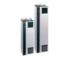
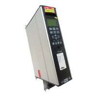
Danfoss VLT 5122 Variable Frequency Drive Manuals
Manuals and User Guides for Danfoss VLT 5122 Variable Frequency Drive. We have
3
Danfoss VLT 5122 Variable Frequency Drive manuals available for free PDF download: Instruction Manual, Operating Instructions Manual, Service Manual
Danfoss VLT 5122 Service Manual (158 pages)
Brand:
Danfoss
| Category:
DC Drives
| Size: 11 MB
Table of Contents
Table of Contents
3
Introduction
9
Purpose
9
Vlt Product Overview
9
For Your Safety
9
Electrostatic Discharge (Esd)
9
Tools Required
11
Additional Tools Recommended for Testing
11
Exploded View D1 Frame Size
12
Exploded View D2 Frame Size
13
Exploded View E Frame Size
14
Section 1 Operator Interface and Drive Control
21
Introduction
21
Normal Display
21
Status Display
22
Factory Default Display Settings
22
Warnings and Alarms
26
Alarms
26
Warnings
26
Service Functions
26
Fault Message Table
27
Drive Inputs and Outputs
28
Input Signals
28
Output Signals
28
Control Terminals
29
Control Terminal Functions
29
Grounding Shielded Cables
31
Section 2 Internal Drive Operation
33
General
33
Description of Operation
33
Logic Section
33
Logic to Power Interface
34
Power Section
35
Sequence of Operation
36
Rectifier Section
36
Intermediate Section
38
Inverter Section
40
Brake Option
42
Cooling Fans
43
Load Sharing
43
Specific Card Connections
43
Section 3 Troubleshooting
45
Troubleshooting Tips
45
Exterior Fault Troubleshooting
45
Fault Symptom Troubleshooting
45
Visual Inspection
46
3 Fault Symptoms
47
Display
47
No Display
47
Intermittent Display
47
Display (Line 2) Flashing
47
WRONG or WRONG LCP Displayed
47
Motor
48
Motor will Not Run
48
Incorrect Motor Operation
49
Warning and Alarm Messages
50
After Repair Tests
57
Section 4 Drive and Motor Applications
59
Torque Limit, Current Limit, and Unstable Motor Operation
59
Overvoltage Trips
60
Mains Phase Loss Trips
60
Control Logic Problems
61
Programming Problems
61
Motor/Load Problems
61
Internal Drive Problems
62
Overtemperature Faults
62
Current Sensor Faults
62
Signal and Power Wiring Considerations for Drive Electromagnetic Compatibility
63
Effects of EMI
63
Sources of EMI
63
EMI Propagation
64
Signal Conductor Currents
64
Preventative Measures
65
Proper EMC Installation
66
Section 5 Test Procedures
67
Introduction
67
Tools Required for Testing
67
Signal Test Board
67
Test Cable
67
5 Test Procedures
68
Static Test Procedures
68
Soft Charge and Rectifier Circuits Test: D-Frame Size
69
Soft Charge Card Fuses
69
Soft Charge Rectifier Test: D-Frame Size
71
Soft Charge Card Connectors
71
Soft Charge and Rectifier Circuits Test: E-Frame Sizes
72
Soft Charge Card Fuse Location
72
Soft Charge Rectifier Test: E-Frame Size
74
Inverter Section Tests
75
Brake IGBT Test
76
Intermediate Section Tests
76
Heatsink Temperature Sensor Test
76
Fan Continuity Tests: D-Frame Size
77
Fan Continuity Tests: E-Frame Sizes
78
Dynamic Test Procedures
79
No Display Test
80
Input Voltage Test
80
Basic Control Card Voltage Test
80
Switch Mode Power Supply (SMPS) Test
81
Zero DC Bus Voltage Test
81
DC under Voltage Test
82
Input Phase Imbalance Test
82
Input Waveform Test
83
Input SCR Test
85
Output Phase Imbalance Test
86
IGBT Gate Drive Signals Test
87
IGBT Switiching Test
90
Brake IGBT Test
90
Current Sensors Test
91
Fan Tests
92
Input Terminal Signal Tests
93
Control Card Test
94
Initial Start up or after Repair Drive Tests
95
Section 6 D-Frame Sizes Disassembly and Assembly Instructions
97
Electrostatic Discharge (Esd)
97
6 Instructions
97
Control Card Cassette
97
Interface Card
98
Power Card
98
Control Card/Power Card Mounting Plate
98
Interface Card, Power Card, and Mounting Plate
98
Gate Drive Card
99
Soft Charge Card
99
Soft Charge Card Assy
99
Capacitor Bank(S)
100
Upper Capacitor Bank D2 Units
100
Lower Capacitor Bank D2 Units
100
Single Capacitor Bank D1 Units
101
Soft Charge (SC) Resistors D2 Units
102
Soft Charge Resistor
102
Soft Charge (SC) Resistors D1 Units
103
D2 Soft Charge Resistor
103
D1 Soft Charge Resistor
104
Input Terminal Mounting Plate Assy
106
Scr/Diode Module D2 Units
107
D2 Scr/Diode Module
110
D1 Scr/Diode Module
110
Scr/Diode Module D1 Units
111
Current Sensor
114
Fan Assembly
115
Fanassembly
115
AC Input Terminals
117
IGBT Modules D2 Units
118
D2 IGBT Modules
118
IGBT Modules D1 Units
121
Section 7 E-Frame Sizes Disassembly and Assembly Instructions
123
Electrostatic Discharge (Esd)
123
7 Instructions
123
Control Card Cassette
123
Interface Card
124
Power Card
124
Control Card/Power Card Mounting Plate
124
Gate Drive Card
125
Soft Charge Card
125
Capacitor Banks
126
Upper Capacitor Bank
126
Lower Capacitor Bank
126
Upper and Lower Capacitor Bank Assemblies
126
Input Terminal Mounting Plate Assy Option
127
Soft Charge Resistor
128
SCR and Diode Modules
129
Current Sensor
132
Current Sensors
132
Fan Assembly
133
Fanassembly
133
AC Input, Motor, Load Sharing or Regen Terminals
134
Terminal Blocks
134
IGBT Modules
135
Section 8 Special Test Equipment
139
Test Equipment
139
Test Cable and SCR Shorting Plug (P/N 176F8439)
139
Test Cable and SCR Shorting Plug
139
Signal Test Board (P/N 176F8437)
140
Signal Test Board Pin Outs: Description and Voltage Levels
140
Signal Test Board
140
Advertisement
Danfoss VLT 5122 Instruction Manual (240 pages)
Brand:
Danfoss
| Category:
DC Drives
| Size: 11 MB
Table of Contents
Table of Contents
4
Safety
7
Safety Regulations
8
Warning against Unintended Start
8
Installation of Mechanical Brake
8
Technical Data
9
General Technical Data
9
Electrical Data
16
Fuses
36
Dimensions
44
Mechanical Dimensions
44
Installation
47
Mechanical Installation
47
Electrical Installation - Mains Supply
61
Safety Grounding
61
Extra Protection (RCD)
61
RFI Switch
61
Installation of Motor Cables
65
Connection of Motor
65
Direction of Motor Rotation
65
Electrical Installation - Brake Cable
66
Electrical Installation - Relay Outputs
66
Electrical Installation - 24 Volt External DC Supply
66
Electrical Installation - Load Sharing
66
Electrical Installation - Brake Resistor Temperature Switch
67
Electrical Installation - Bus Connection
67
Installation of Control Cables
68
Connection Examples
71
Operation of the VLT
74
Control Panel (LCP)
74
Control Panel - Display
74
Control Panel - Leds
75
Control Panel - Control Keys
75
Quick Setup
78
Parameter Selection
78
Menu Mode
78
Manual Initialization
80
Programming
82
Operation & Display
82
Load and Motor
90
References and Limits
103
Parameters - Inputs and Outputs
112
Special Functions
128
Parameters - Serial Communication
144
Parameters - Technical Functions and Diagnostics
152
Messages
159
Trouble-Shooting
159
Display - Status Messages
160
Warnings and Alarms
163
Warnings
164
Examples of Use
171
Conveyor Belt
171
Pump
172
Gantry Crane
173
Torque Control, Speed Feedback
174
VLT 5000 Controllers
175
PID for Process Control
177
PID for Speed Control
178
PID for Torque Controller (Open Loop)
179
Ec/Emc
180
CE Labelling
180
Electrical Installation
184
Electrical Installation - EMC Precautions
184
Electrical Installation, Selection of EMC-Correct Cables
187
List of Functions
188
Setting of Parameters
188
Local and Remote Control
191
Control with Brake Function
192
References - Single References
193
References - Multi-References
195
Automatic Motor Adaptation, AMA
199
Mechanical Brake Control
201
PID for Process Control
203
PID for Speed Control
204
Quick Discharge
205
Flying Start
207
Normal/High Overload Torque Control,Open Loop
209
Programming of Torque Limit and Stop
209
Galvanic Isolation (PELV)
210
Extreme Running Conditions
212
Danfoss VLT 5122 Operating Instructions Manual (192 pages)
Frequency Converters
Brand:
Danfoss
| Category:
Media Converter
| Size: 7 MB
Table of Contents
Operating Instructions
1
Table of Contents
2
Safety
4
Safety Regulations
5
Warning against Unintended Start
5
Installation of Mechanical Brake
5
Quick Setup
7
Introduction
7
Available Literature
10
Technical Data
11
General Technical Data
11
Electrical Data
18
Fuses
35
Mechanical Dimensions
38
Installation
41
Mechanical Installation
41
Safety Earthing
44
Extra Protection (RCD)
44
Electrical Installation - Mains Supply
44
Electrical Installation - Motor Cables
44
Connection of Motor
45
Direction of Motor Rotation
45
Electrical Installation - Brake Cable
46
Electrical Installation - Brake Resistor Temperature Switch
46
Electrical Installation - Loadsharing
46
Electrical Installation - 24 Volt External DC Supply
48
Electrical Installation - Relay Outputs
48
Electrical Installation - Control Cables
56
Electrical Installation - Bus Connection
58
Electrical Installation - EMC Precautions
59
Use of Emc-Correct Cables
62
Electrical Installation - Earthing of Control Cables
63
RFI Switch
64
Operation of the Frequency Converter
67
Control Panel (LCP)
67
Control Panel - Display
67
Control Panel - Leds
67
Control Panel - Control Keys
67
Quick Setup
70
Parameter Selection
71
Menu Mode
71
Initialisation to Factory Setting
72
Connection Examples
75
Application Configuration
77
Setting of Parameters
77
Special Functions
80
Local and Remote Control
80
Control with Brake Function
81
References - Single References
82
References - Multi-References
84
Automatic Motor Adaptation, AMA
87
Mechanical Brake Control
89
PID for Process Control
91
PID for Speed Control
92
Quick Discharge
93
Flying Start
95
Normal/High Overload Torque Control,Open Loop
96
Programming of Torque Limit and Stop
96
Programming
98
Parameters - Operation and Display
98
Parameters - Load and Motor
104
Parameters - References and Limits
115
Parameters - Inputs and Outputs
123
Parameters - Special Functions
139
Parameters - Serial Communication
153
Parameters - Technical Functions and Diagnostics
159
Miscellaneous
165
Trouble-Shooting
165
Display - Status Messages
166
Warnings and Alarms
169
Warnings
170
Index
188
Advertisement
Advertisement
Related Products
Danfoss VLT 5100
Danfoss VLT 5125
Danfoss VLT 5150
Danfoss VLT 5122-5302
Danfoss VLT 5350
Danfoss VLT 5003
Danfoss VLT 5011
Danfoss VLT 5200
Danfoss VLT 5001-5006
Danfoss VLT 5352-5552
Danfoss Categories
Controller
DC Drives
Thermostat
Control Unit
Air Compressor
More Danfoss Manuals
Login
Sign In
OR
Sign in with Facebook
Sign in with Google
Upload manual
Upload from disk
Upload from URL