Sign In
Upload
Manuals
Brands
Brother Manuals
All in One Printer
DCP-6690CW
Brother DCP-6690CW Manuals
Manuals and User Guides for Brother DCP-6690CW. We have
4
Brother DCP-6690CW manuals available for free PDF download: Service Manual, Network User's Manual, User Manual, Quick Setup Manual
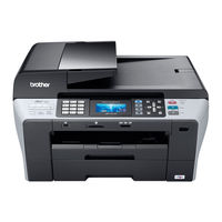
Brother DCP-6690CW Service Manual (507 pages)
Brand:
Brother
| Category:
All in One Printer
| Size: 41.55 MB
Table of Contents
Service Manual
1
Chapter 3 Theory of Operation
4
How this Manual Is Organized
4
Choosing a Location
7
Safety Precautions
7
Symbols Used in the Documentation
7
To Use the Machine Safely
8
Important Safety Instructions
12
Parts Names and Functions
14
Chapter 1 Parts Names and Functions
16
Front View
16
Outline
16
Back View
17
Control Panel
18
Dcp6690Cw
18
LCD Indications
19
Mfc6490Cw
20
LCD Display Screen
22
Mfc6890Cdw
23
LCD Screen
25
Combinations of Two Keys for Special Functions
26
Components
27
CHAPTER 2 Specifications
28
Table of Contents
29
General Specifications
30
Power Consumption
30
Dimensions (W X D X H)
31
Brother Paper
32
Paper Specifications
32
Recommended Media
32
Paper Weight, Thickness and Capacity
33
Cut Sheet Paper
34
Envelopes
34
Printable Area
34
Specifications List
35
Theory of Operation
53
Overview
55
Mechanical Components
56
Printing Mechanism
56
Scanner Mechanism
56
Duplex Print Mechanism (for Duplex Print Models)
57
Paper Pulling-In, Registration, Feeding and Ejecting Mechanisms
57
Recording Paper Path
57
Scanner Mechanism
59
ADF Scanning
61
CIS Drive Mechanism
61
Flat-Bed Scanning
61
Printing Mechanism
62
1 ] Overview
65
Ink Supply and Ink Jet Mechanism
65
2 ] Features
66
3 ] Head/Carriage Unit
67
Front End
68
Nozzle Array (Head Bottom Plate Viewed from the Bottom)
68
Ink Spray Function
69
Back End
70
Back End Components and Their Main Roles
70
Damper ASSY (Cyan)
70
Damper ASSY (Magenta)
70
Air Buffering
71
Damping
71
Ink Pressure in the Ink Supply Tubes
72
Tip: Air Bubble Growth
72
Tip: What's so Bad about Air Bubble Growth?
73
4 ] Ink Cartridges
74
Filled with Ink
74
Ink Cartridge Features
74
Ink Near-Empty/Ink Empty
74
Disc Valve D
75
Disc Valve S
75
Ink Backflow Prevention in Unsealing a New Ink Cartridge
75
Ink Cartridge Components and Their Main Roles
75
Discrimination of Ink Cartridge Type
76
Ink Near-Empty/Ink Empty Detection
76
5 ] Ink Refill Assembly
77
6 ] Ink Supply Tubes
78
Ink Refill Assembly Components and Their Main Roles
78
1 ] Overview
79
Head Maintenance Mechanism
79
2 ] Maintenance Unit Components
80
Cap Lift Cam and Its Gear
80
Head Cap Holder
80
Head Cap Unit
80
Air Vent Cap and Rods
81
Head Wiper
81
Pump Switching Unit
81
Purge Cam
81
3 ] Mechanisms Constituting the Head Maintenance Mechanism
82
Carriage Lock Mechanism
82
Head Capping Mechanism
82
Purge Mechanism
83
Draining Ink
84
Switching Pump
84
Air Removing Mechanism
85
Head Wiper Mechanism
86
4 ] Power Transmission Route to the Head Maintenance Mechanism and Motor Rotational Direction
87
5 ] Purge Types, Ink Usage, Purge Counts, and Purge Codes
90
6 ] Ink Cartridge Capacities and the Number of Printable Pages Per Ink Cartridge
90
Carriage Drive Mechanism
91
Adjusting the Print Head Angle Relative to Carriage
92
Viewed from the Bottom
92
Height Adjustment of the Head/Carriage Unit
93
Paper Pulling-In, Registration, Feeding and Ejecting Mechanisms
95
Print Quality
95
Power Transmission Routes of the ASF Motor and Paper Feed Motor
96
High-Speed Feed Mode
97
Normal SF Mode
97
Normal SF, High-Speed Feed, and LT Modes
97
LT Mode
98
Fixed-Speed Paper Feed
99
Other Controls
99
Paper Feed Position and Speed Control
99
Paper Stop Position Control
99
Duplex Print Mechanism
100
DX Flapper Drive Mechanism
101
Torque Transmission Route from the ASF Motor to the DX Flapper
101
Engagement/Disengagement of Torque Transmission by the SB Clutch Lever
102
SB Roller Drive Mechanism
102
Torque Transmission Route from the Paper Feed Motor to the SB Roller
102
Bottom-Face Printing
103
Sensors and Actuators
105
Components
109
Control Electronics
109
Recording Paper Feeding/Ejecting Control in Duplex Printing
103
Top-Face Printing
103
Error Indication and Troubleshooting
110
Chapter 4 Error Indication and Troubleshooting
113
Error Indication
113
Equipment Errors
113
1 ] Error Messages Appearing on the LCD
114
2 ] Error Codes Contained in "MACHINE ERROR X X" Messages
120
Error Codes for Duplex Print Models Only
120
Error Codes for All Models
125
Communications Errors (for MFC Only)
142
Calling
143
Command Reception
143
Definition of Error Codes on the Communications List
143
Compatibility [Checking the NSF and DIS
144
Instructions Received from the Remote Terminal
145
DCN Reception
146
ID Checking
146
TCF Transmission/Reception
146
Signal Isolation
147
Video Signal Reception
147
Equipment Error
148
General Communications-Related
148
Maintenance Mode
148
Checking Prior to Troubleshooting
149
Introduction
149
Power Requirements
149
Precautions
149
1 ] Control Panel and LCD Problems
151
2 ] FAX Problems (for MFC Only)
151
3 ] Communications Problems (for MFC Only)
151
Troubleshooting Based on Problem Type
151
4 ] Paper/Document Feeding Problems
152
5 ] Print-Image Problems
153
Examples of Defective Images
153
6 ] PC-Driven Printing Problems
159
7 ] Printing from Memory Cards--Compact Flash, Memory Stick, SD Memory Card, XD-Picture Card and USB Flash Memory Drive
159
8 ] Wireless LAN (WLAN)
160
9 ] Others
160
Paper Jams
161
Problems Due to Machine Malfunction
161
Problems Encountered Frequently in the Past
161
2 ] "MACHINE ERROR 4F" Error Message
162
3 ] Ink-Related Problems
162
4 ] Auto Document Feeder (ADF) Malfunction
163
1 ] ADF Mechanism
164
Possible Component Defects and Resulting Problems
164
2 ] Scanner Mechanism
165
3 ] Head/Carriage Unit Drive and Purge Mechanisms
166
4 ] Print Head Mechanism
167
5 ] Duplex Print Mechanism
168
6 ] Sheet Feeder (SF) Mechanism
168
7 ] Paper Feeding Mechanism
169
8 ] Speaker
169
9 ] Control Panel
169
10 ] Pcbs
170
11 ] Adjustments/Data in the Memories
171
Problems Due to the User's Actions
161
Handling Data Held in the Machine Prior to Repair
172
At the User Site
174
Operating Procedure
174
Transferring Received Fax Data
174
Cover Page Sample
176
End Page Sample
176
Backing up Machine Information
177
Models with Touch Panel
177
Models Without Touch Panel
177
Disassembly/Reassembly and Lubrication
179
Chapter 6 Disassembly/Reassembly and Lubrication
182
Disassembly/Reassembly
182
Safety Precautions
182
Tightening Torque
183
Preparation
184
How to Access the Target Component
185
Disassembly Flowchart
186
Sensors, Encoders, and Thermistors
186
Scanner Cover (Scanner Unit)
187
Assembling Notes
192
ADF & Document Cover ASSY
193
Disassembly of ADF & Document Cover ASSY
195
Document Support and Document Stopper
195
ADF Handle Cover and ADF Front Cover
196
ADF Cover and Document Pressure Roller 1
197
ADF Rear Cover
197
Document Pull-In/Separation Roller ASSY
198
Separation Rubber and Related Plates
198
Upper ADF Chute and Document Guides (F and R)
199
Lower ADF Chute
201
Document Feed Roller
202
Document Ejection Roller ASSY
203
ADF Drive Unit and ADF Motor
204
Document Front and Rear Sensor Actuators
205
Document Width Sensor Actuator
205
Document Width Sensor PCB
205
Document Pressure Bar
207
Edge Covers L and R, Scanner Cover Support, and Damper
210
Control Panel ASSY
211
Disassembly of Control Panel ASSY
213
Backup Battery
218
Side Covers, Speaker, Upper Cover and Encoder Guard Film
218
Ink Cartridge Cover, Media Module Cover, Front Cover, and WLAN PCB
224
Main PCB
226
Mfc6490Cw/Mfc6890Cdw
227
Assy
231
Outer and Inner Back Covers*, LT Cover, and LT Paper Pull-In Roller
231
MJ/PS Shield Unit (MJ PCB* and Power Supply PCB)
234
Head/Carriage Unit and Ink Refill ASSY
239
CR Encoder Strip
240
Tube Support Plate and Tube Support Wire
240
Head Cover
241
Carriage PCB ASSY (Carriage PCB with Head Flat Cables)
242
Head Joint, Ink Refill ASSY, and Ink Cartridge Detection Sensor PCB
243
Head/Carriage Unit and CR Timing Belt
246
Routing the Head Flat Cables When Mounting the Carriage PCB ASSY
250
Viewed from the Rear
250
Ink Absorber Box, Ink Absorber Felt, and PF Encoder Disk
252
Duplex Unit (for Duplex Print Models)
254
Engine Unit and Flushing Box
258
Components on the Engine Unit
262
Link Gear Holder DX ASSY (for Duplex Print Models)
263
Maintenance Unit
264
ASF Motor
265
Carriage Motor
266
Star Wheel Holder
267
Paper Pull-In Rollers R and L, and ASF Gear Shaft Outer
272
Paper Tray ASSY #1 (DX Paper Tray ASSY #1*)
274
Paper Tray ASSY #2
275
Routing of the Harnesses, Flat Cables, and Ink Supply Tubes
276
On the Document Cover
277
On the Lower ADF Chute
277
Routing C: Panel-Main Harness on the Control Panel ASSY
278
Routing D: Battery Harness and Speaker Harness
278
Routing E: WLAN PCB Harness
279
Speaker Harness
279
On the Lower Cover
280
On the SDAA Enclosure
280
Routing H: Ink Supply Tubes
283
Routing I: Head Flat Cables
284
Routing J: DX Cover Sensor Harness
284
On the Inner Chute ASSY
285
Routing K: PF Encoder/Registration Sensor Harness
285
Routing M: Harnesses, Flat Cables and Ink Tubes on the Lower Cover
286
Lubrication
287
Motor Plate and CR Guide Rail (Bottom Edges)
288
Switching Lever Guide
288
CR Guide Rail and CR Support Chassis (Upper Face)
289
Lubrication Procedure
289
CR Support Chassis (Front and Rear Sides of Upright Rear Edge)
290
Paper Pull-In Idle Gear and Paper Pull-In Roller L
291
Adjustments and Updating of Settings
292
Required after Parts Replacement
292
Requirements
295
Chapter 7 Adjustments and Updating of Settings
295
Preparation
295
Installing the Maintenance USB Printer Driver
297
Installing the Brother Maintenance USB Printer Driver
297
1 ] Update the Head Property Information Stored in the EEPROM on the Main PCB
301
If You Replace the Head/Carriage Unit or Engine Unit
301
2 ] Clean the New Head/Carriage Unit (Function Code 76)
305
3 ] Print out a Test Pattern (Function Code 09)
306
Print Quality Check
306
4 ] Correct the Positioning Error of the Head/Carriage Unit
307
5 ] Update the Paper Feeding Correction Value (Function Code 58)
310
For the Paper Ejection Roller Adjustment Using Paper Tray
311
For the Paper Feed Roller Adjustment Using Paper Tray
311
For the Paper Ejection Roller Adjustment Using Paper Tray #2
312
6 ] Align Vertical Print Lines (Function Code 65)
316
Vertical Alignment Check Patterns
316
7 ] Adjust Margins in Borderless Printing (Function Code 66)
318
Left and Right Margin Adjustment
318
Bottom Margin Adjustment
319
8 ] Print out a Total Check Pattern
323
Total Check Pattern
324
10 ] Replace the Ink Cartridges with the Protective Part
325
9 ] Switch Back to Standby
325
1 ] Load Update Programs/Data
326
2 ] Initialize the EEPROM on the Main PCB (Function Code 01)
326
3 ] Customize the EEPROM on the Main PCB (Function Code 74)
326
4 ] Check the Control Panel PCB for Normal Operation (Function Code 13)
326
5 ] Check the Sensor Operation (Function Code 32)
326
6 ] Acquire White Level Data and Set CIS Scanner Area (Function Code 55)
326
7 ] Set an ID Code and Update the Head Property Information
326
If You Replace the Main Pcb
326
8 ] Back up Machine Information (Function Code 46)
328
10 ] Align Vertical Print Lines (Function Code 65)
329
11 ] Adjust Margins in Borderless Printing (Function Code 66)
329
12 ] Print out an ADF Copy Chart and Make a Copy of that Chart in ADF Scanning
329
9 ] Update the Paper Feeding Correction Value (Function Code 58)
329
Adjust the Touch Panel (Function Code 78) (for Models with Touch Panel)
329
Check LCD Operation and Specify the LCD Type (Function Code 12)
329
Get EEPROM Data (Incl. MAC Address) from the WLAN PCB (for Wireless LAN-Enabled Models)
329
16 ] Switch Back to Standby
330
1 ] Check the "Total Quality Check Pattern
331
If You Replace the Adf Unit or Adf-Related Parts
331
Print out an ADF Copy Chart and Make a Copy of that Chart in ADF Scanning
331
Check Items on the ADF COPY CHART
332
1 ] Reset each of the Purge and Flushing Counters
334
If You Replace the Ink Absorber Box or Flushing Box
334
1 ] Transfer EEPROM Data (Incl. MAC Address) to the Main PCB
335
2 ] Check the "Total Quality Check Pattern
335
2 ] Check the Operation of the Control Panel PCB (Function Code 13)
335
Acquire White Level Data and Set CIS Scanner Area (Function Code 55)
335
Adjust the Touch Panel (Function Code 78) (for Models with Touch Panel)
335
Check LCD Operation and Specify the LCD Type (Function Code 12)
335
If You Replace the Control Panel Assy or Control Panel Pcb
335
If You Replace the Scanner Cover (Scanner Unit)
335
If You Replace the Wlan Pcb (for Wireless Lan-Enabled Models)
335
Print out an ADF Copy Chart and Make a Copy of that Chart in ADF Scanning
335
1 ] Check the Paper Feeding and Ejecting Operations in Duplex Printing
336
If You Replace the Duplex Unit (for Duplex Print Models)
336
Cleaning
337
Chapter 8 Cleaning
339
Cleaning the External and Internal Surface of the Machine
339
Cleaning the Maintenance Unit
340
Wiping off with a Cloth
342
Cleaning the Paper Pull-In Rollers (Paper Pick-Up Rollers) (for Duplex Print Models)
342
Cleaning with a Cleaning Kit
343
Maintenance Mode
344
Chapter 9 Maintenance Mode
347
Entry into the Maintenance Mode
347
List of Maintenance-Mode Functions
349
User-Access to the Maintenance Mode
350
Detailed Description of Maintenance-Mode Functions
351
EEPROM Parameter Initialization (Function Code 01, 91)
351
Function Code
351
Printout of Scanning Compensation Data (Function Code 05)
352
Scanning Compensation Data List
353
ADF Performance Test (Function Code 08)
354
Test Pattern (Function Code 09)
355
Test Pattern
356
Firmware Switch Setting and Printout (Function Codes 10 and 11) (User-Accessible)
357
Firmware Switches (WSW01 through WSW60)
357
Details of Firmware Switches
359
Printout of Firmware Switch Data
360
Configuration List
361
Operational Check of LCD and Specifying of the LCD Type
362
Operational Check of LCD and Specifying of the LCD Type (Function Code 12) (User-Accessible)
362
Operational Check of Control Panel PCB (Function Code 13)
364
Updating of Firmware Using an External Memory (Function Code 28)
365
Sensor Operational Check (Function Code 32)
366
Backup of Machine Information (Function Code 46) (User-Accessible)
368
Restoration Procedure
369
Setting of Country/Language (Function Code 52) (User-Accessible)
370
Transfer of Received FAX Data And/Or Equipment's Log
371
Transfer of Received FAX Data And/Or Equipment's Log (Function Code 53) (User-Accessible)
371
Fine Adjustment of Scanning Start/End Position (Function Code 54)
373
Acquisition of White Level Data and CIS Scanner Area Setting (Function Code 55)
374
Updating of Paper Feeding Correction Value (Function Code 58)
375
Checking of CIS Travel (Function Code 59)
381
Travel Check of the Head/Carriage Unit and Initial Setup Mode
382
Travel Check of the Head/Carriage Unit and Initial Setup Mode (Function Code 63)
382
Alignment of Vertical Print Lines in Monochrome (Function Code 65)
383
Margin Adjustment in Borderless Printing (Function Code 66) (User-Accessible)
386
Updating of Property Data (Function Code 68)
391
Head/Carriage Unit Traveling Speed Check (Function Code 69)
392
EEPROM Customizing (Function Code 74)
393
Travel of Head/Carriage Unit
394
Travel of Head/Carriage Unit (for Removing Paper Particles and Dust Accumulated on the Maintenance Unit) (Function Code 75) (User-Accessible)
394
Purge Operation (Function Code 76) (User-Accessible)
395
Purge Types, Ink Usage, Purge Counts, and Purge Codes
396
Resetting Purge or Flushing Counter
397
Adjustment of Touch Panel (Function Code 78)
398
Display of the Equipment's Log (Function Code 80) (User-Accessible)
400
Equipment Error Code Indication (Function Code 82) (User-Accessible)
402
Output of Transmission Log to the Telephone Line (Function Code 87)
402
Assurance Mode Switch Setting (Function Code 88) (User-Accessible)
403
Ams01
404
Ams02
405
Selectors 5 and 6: Assurance Print 1 and 2
405
Selectors 7 and 8: Workaround for False Jam Detection
405
Selector 6: Registration Time Offset to Slipping in Plain Paper
406
Selectors 3 to 5: Paper Feed Amount Compensation
406
Selector 7: Unidirectional Print for Higher Print Quality
407
Selector 8: Improvement of Paper Feeding Reliability
407
Ams03
408
Selector 1: Protection of Head Caps from Drying
408
Selector 4: Purge more Powerful than Normal Purge
408
Selectors 2 and 3: Auto Capping Start Time
408
Ams04
409
Selector 3: Black Ink Print Mode
409
Selectors 4 and 8: Automatic Purging for Color Ink and for Black Ink
409
Selectors 6 and 7: Automatic Purging Interval
409
Ams05
410
Selector 3/4: Enabling/Disabling the Head-Platen Gap Offset Settings
410
Selector 5: Reduction of Occurrences of Paper Jams
410
Cancellation of the Pin TX Lock Mode (Not Applicable to Japanese and U.S.A. Models)
413
Reading Labels
414
Serial Number Label for the Machine Itself
415
Head Property Labels
416
On the Head/Carriage Unit
416
Manufacturing Information Label for an Ink Cartridge
417
Firmware Installation
418
Loading the Programs to the Flash ROM
419
After Replacing the Main PCB with a New One
423
Loading the Programs Onto the Flash ROM of the Machine
423
To Load Programs from the PC
425
To Load Programs Using an External Memory
426
EEPROM Customizing Codes
427
Firmware Switches (WSW)
430
Selectors 1 and 2: Dial Pulse Generation Mode
433
Selectors 3 and 4: Break Time Length in Pulse Dialing
433
Wsw01
433
Selector 8: Default Dialing Mode, Pulse (DP) or Tone (PB) Dialing
434
Selectors 5 and 6: Inter-Digit Pause
434
Selectors 5 through 8: Attenuator for Pseudo Ring Backtone to the Line
435
Tone Signal Transmission Time Length and Min. Pause in Tone Dialing
435
Wsw02
435
CNG Detection When Sharing a Modular Wall Socket with a Telephone
436
Detection Time Length of PBX Dial Tone, Required for Starting Dialing
436
Wsw03
436
Selector 1: Earth Function in Transfer Facility
437
Selectors 6 and 7: Dial Tone Detection in PBX
437
Wsw04
437
Selector 4: Dual Tone Detection Sensitivity in ICM Recording
438
Selectors 2 and 3: Dual Tone Detection Frequency in ICM Recording
438
Selectors 6 through 8: Break Time Length for Flash Function
438
Wsw05
438
Selector 4: Max. Pause Time Allowable for Remote ID Code Detection
439
Selector 7: Busy Tone Detection in Automatic Receiving Mode
439
Selectors 1 through 3: 1St Dial Tone Detection
439
Selectors 5 and 6: Busy Tone Detection in Automatic Sending Mode
439
Wsw06
440
Allowable Instantaneous Interrupt During Reception of 2Nd Dial Tone
441
Selector 7: No. of 2Nd Dial Tone Detection Cycles
441
Selectors 1 through 3: Pause Key Setting and 2Nd Dial Tone Detection
441
Selectors 4 through 6: Detection of International Tone
441
Selector 3: Line Current Detection
442
Selectors 1 and 2: Dial Tone Frequency Band Control
442
Selectors 4 through 6: 2Nd Dial Tone Detection Level
442
Wsw07
442
Selectors 1 through 3: 1St Dial Tone Detection Time Length
443
Selectors 4 and 5: Time-Out Length for 1St and 2Nd Dial Tone Detection
443
Wsw08
443
Selector 1: Frame Length Selection
444
Selector 2: Use of Non-Standard Commands
444
Selectors 3 and 4: No. of Retries
444
Wsw09
444
Selector 3: Time Length from CML on to CNG Transmission
445
Selector 4: Time Length from CML on to CED Transmission
445
Time Length from Transmission of the Last Dial Digit to CML on
445
Wsw10
445
Selectors 1 and 2: Busy Tone Frequency Band Control
446
Selectors 3 through 8: ON/OFF Time Length Ranges for Busy Tone
446
Wsw11
446
Selector 7: Line Connection Timing (Not Used.)
447
Wsw12
447
Selectors 1 and 2: Cable Equalizer
448
Selectors 3 and 4: Reception Level
448
Selectors 5 through 8: Modem Attenuator
448
Wsw13
448
Frequency Band Selection for Incoming Calling Signal
449
Selectors 5 through 8: No. of Rings in AUTO ANS Mode
449
Wsw14
449
Selector 8: CRP Option
450
Selectors 1 through 6: Redial Interval and No. of Redialings
450
Wsw15
450
Selector 2: ITU-T (CCITT) Superfine Recommendation
451
Selector 7: Max. Document Length Limitation
451
Selector 8: Stop Key Pressed During Reception
451
Wsw16
451
Selector 5: Calendar Clock Type
452
Selector 7: Non-Ring Reception
452
Selectors 1 and 2: Off-Hook Alarm
452
Wsw17
452
Selector 6: Registration of Station ID
453
Selectors 2 and 3: Detection Enabled Time for CNG or "No Tone"
453
Selectors 7 and 8: Tone Sound Monitoring
453
Wsw18
453
First and Last Choices of Transmission Speed for Fallback
454
Selector 7: V.34 Mode
454
Wsw19
454
Selector 1: EP Tone Prefix
455
Selectors 2 and 3: Overseas Communications Mode
455
Wsw20
455
"No Tone" Detection Period During Recording of ICM
456
Selector 8: Limitation on CNG Detection
456
Selectors 6 and 7: Taping the Call
456
Wsw21
456
Selector 3: Call Waiting Caller ID
457
Selectors 5 through 8: Acceptable TCF Bit Error Rate (%)
457
Wsw22
457
Selector 1: Starting Point of Training Check (TCF)
458
Selectors 2 and 3: Allowable Training Error Rate
458
Selectors 4 and 5: Decoding Error Rate for Transmission of RTN
458
Wsw23
458
Attenuator for Playback of ICM/OGM to the Line
459
Selectors 1 and 2: Maximum OGM Recording Time
459
Time Length from CML on to Start of Pseudo Ring Backtone Transmission
459
Wsw24
459
Delay Time for Starting "No Tone" Detection in the External TAD Mode
460
Pause between Paging Number and PIN
460
Threshold Level of "No Tone" Detection in the External TAD Mode
460
Wsw25
460
No. of CNG Cycles to be Detected
461
Wsw26
461
Selector 2: Ringer off Setting
462
Selector 3: Automatic Playback of OGM When Switched to the TAD Mode
462
Selector 4: Detection of Distinctive Ringing Pattern
462
Wsw27
462
Transmission Level of DTMF High-/Low-Band Frequency Signal
463
Wsw28
463
Prompt Beep for Activity Report
464
Wsw29
464
Dial Tone/Busy Tone Detection Level During Recording of ICM
465
Wsw30
465
Limitation of Reduction Ratio in Copying
466
Wsw31
466
Selectors 5 and 6: Default Resolution
467
Selectors 7 and 8: Default Contrast
467
Wsw32
467
Comfortable Noise Level
468
Threshold Level of "No Tone" Detection During Recording of ICM
468
Wsw33
468
Erasing Time Length of ICM Tone Recorded Preceding the Tone Detection
469
Wsw34
469
Wsw35
470
Selector 1: ECP Mode
471
Selector 2: Recovery from Inactive PC Interface
471
Selector 3: PC Power-Off Recognition Time
471
Wsw36
471
Wsw37
472
Selector 3: Sending Level of Guard Tone at Phase 2
473
Selectors 1 and 2: Setting of the Equalizer
473
Stepping down the Transmission Speed at Fallback each
473
Wsw38
473
Wsw39
474
Selectors 3 through 8: Masking of Symbol Rate(S)
475
Wsw40
475
Modem Attenuator
476
ON-Duration of the Scanning Light Source at Room Temperature
476
Wsw41
476
Selector 1: Insertion of Mail Header into Outgoing Mails
477
Selector 8: JPEG Coding
477
Wsw42
477
Wsw43
477
Effective Time Length of the White Level Compensation Data Obtained
478
Wsw44
478
Selector 7: Standby Position of the CIS Unit
479
Selector 8: Line Polarity Reversal Detector
479
Wsw45
479
Previous Filtering Parameters for White Level Compensation
480
Selector 3: Parallel Port Output Pins Kept at High Level
480
Selectors 1 and 2: Monitoring the PC ON/OFF State
480
Wsw46
480
Delay of FAX Line Disconnection When Switching to the Pseudo-Ringing
481
Handling Paper at the Occurrence of Paper Feed Timing Error
481
Selector 2: Reduction of Document Size in Real-Time Transmission
481
Wsw47
481
Wsw48
482
Wsw49
482
Current Control to be Applied Immediately after Connection of the Line
483
Selector 8: Black Ink Print Mode
483
Selectors 4 and 5: Command Flag Detection Time
483
Wsw50
483
Selector 2: CR Motor Control for Reducing Torque Fluctuation
484
Selectors 5 through 7: Transmitter Level and Echo Suppression
484
Wsw51
484
Selector 8: Dial Number Being Displayed During Faxing
485
Selectors 4 through 6: External Telephone Pseudo Ring Signal Frequency
485
Wsw52
485
Selector 8: JPEG Decompressor
486
Selectors 3 through 6: FSK Receive Timing Delay for Caller ID
486
Wsw53
486
Extension of "No. of CNG Cycles to be Detected" for Easy Receive Mode
487
Selector 4: Recovery of Cordless Handset ID
487
Selectors 1 and 2: Pictbridge Command Delay Time
487
Wsw54
487
Selector 7: Transmission of Caller ID Wetting Pulse
488
Switching between DTMF and FSK for Caller ID
488
Wsw55
488
Wsw56
488
Caller ID Judgment Voltage Level to Detect Line Polarity Reversal
489
Start Key on the Machine after Dialing with Cordless Handset
489
Time Limit for Judging a Caller ID Burst Ring
489
Wsw57
489
Wsw58
490
Selector 1: Transmission of USB Serial Number to PC
492
Selector 2: Extension of the Waiting Time between Ansam and DIS
492
Wsw59
492
Improvement of DTMF Detection Function
493
Key Repeat Start Time and Interval for the Touch Panel
493
Wsw60
493
Adjustment of Temporary Connection Timing of Caller ID
494
Selector 6: Output of CNG Detection Result to the Activity Report
494
Wiring Diagrams
495
Circuit Diagrams
498
Mj Pcb
499
Deletion of Personal Information
504
Deleting Personal Info from the Machine
505
Using Function Code 01
505
Backup Battery
506
Advertisement
Brother DCP-6690CW Network User's Manual (175 pages)
Multi-Protocol On-Board Ethernet Multi-Function Print Server and Wireless (IEEE 802.11b/g) Ethernet Multi-function Print Server
Brand:
Brother
| Category:
Print Server
| Size: 5.92 MB
Table of Contents
Compilation and Publication Notice
3
Important Note
3
Brother Numbers
4
For Customer Service
4
Table of Contents
6
1 Introduction
11
Overview
11
Network Features
12
Network Printing
12
Network Scanning
12
Network PC-FAX (Not Available for DCP Models)
12
Network Photocapture Center
12
Management Utilities
13
Internet Fax/Scan to E-Mail Server (MFC-6490CW: Standard, MFC-5890CN: Available as a Download)
13
Types of Network Connections
14
Wired Network Connection Example
14
Network Shared Printing
15
Wireless Network Connection Examples
16
Protocols
17
TCP/IP Protocols and Functions
17
Other Protocol
18
2 Configuring Your Machine for a Network with an Ethernet Cable Connection
19
Overview
19
IP Addresses, Subnet Masks and Gateways
19
IP Address
19
Subnet Mask
20
Gateway (and Router)
20
Step by Step Chart
21
Setting up the IP Address and Subnet Mask
22
Using the Bradmin Light Utility to Configure Your Machine as a Network Printer
22
Using the Control Panel to Configure Your Machine for a Network
24
Using Other Methods to Configure Your Machine for a Network
24
Changing the Print Server Settings
25
Using the Bradmin Light Utility to Change the Print Server Settings
25
Using the Bradmin Professional Utility to Change the Wireless Settings (for Windows ® )
26
Using the Remote Setup to Change the Print Server Settings (Not Available for DCP Models)
27
Using the Control Panel to Change the Print Server Settings
27
3 Configuring Your Machine for a Wireless Network
28
Overview
28
Wireless Network Terms and Concepts
29
SSID (Service Set Identifier) and Channels
29
Authentication and Encryption
29
Encryption Methods
30
Step by Step Chart for Wireless Network Configuration
31
For Infrastructure Mode
31
For Ad-Hoc Mode
32
Confirm Your Network Environment
33
Connected to a Computer with an Access Point in the Network (Infrastructure Mode)
33
Connected to a Wireless Capable Computer Without an Access Point in the Network (Ad-Hoc Mode)
33
Confirm Your Wireless Network Setup Method
34
Configuration Using the Machine's Control Panel Setup Wizard to Configure Your Wireless Network Machine
34
Configuration Using the SES/WPS/AOSS Control Panel Menu (Infrastructure Mode Only)
34
Configuration Using the PIN Method of Wi-Fi Protected Setup™ (Infrastructure Mode Only)
35
Configuration Using the Brother Installer Application on the CD-ROM to Configure Your Wireless Network Machine
36
Configuring Your Machine for a Wireless Network
37
Using the Setup Wizard from the Control Panel
37
Using the SES/WPS/AOSS Control Panel Menu to Configure Your Machine for a Wireless Network
41
Using the PIN Method of Wi-Fi Protected Setup
45
Using the Brother Automatic Installer Application on the CD-ROM to Configure Your Machine for a Wireless Network
47
4 Wireless Configuration for Windows Using the Brother Installer Application
48
(Not Available for MFC-5490CN and MFC-5890CN)
48
Configuration in Infrastructure Mode
48
Before Configuring the Wireless Settings
48
Configure the Wireless Settings
49
Configuration Using the SES/WPS/AOSS Control Panel Menu (One-Push Method)
55
Before Configuring the Wireless Settings
55
Configure the Wireless Settings
55
Configuration in Ad-Hoc Mode
60
Before Configuring the Wireless Settings
60
Configure the Wireless Settings
60
5 Wireless Configuration for Macintosh Using the Brother Installer Application
68
(Not Available for MFC-5490CN and MFC-5890CN)
68
Configuration in Infrastructure Mode
68
Before Configuring the Wireless Settings
68
Configure the Wireless Settings
69
Configuration Using the SES/WPS/AOSS Control Panel Menu (One-Push Method)
75
Before Configuring the Wireless Settings
75
Configure the Wireless Settings
75
Configuration in Ad-Hoc Mode
79
Before Configuring the Wireless Settings
79
Configure the Wireless Settings
79
6 Control Panel Setup
87
Network Menu
87
Tcp/Ip
87
For Touchscreen Models
88
Setup Misc. (MFC-5490CN Only)
100
Setup Wizard (Wireless Network Only)
100
SES/WPS/AOSS (Wireless Network Only)
100
WPS W/Pin Code (Wireless Network Only)
100
WLAN Status (Wireless Network Only)
101
Ethernet (Wired Network Only)
105
E-Mail/I-FAX (for MFC-6490CW)
106
Scan to FTP (for MFC-5890CN and MFC-6490CW)
117
Time Zone (for MFC-6490CW)
120
Network I/F (Not Available for MFC-5490CN and MFC-5890CN)
121
Restoring the Network Settings to Factory Default
122
Printing the Network Configuration List
123
7 Driver Deployment Wizard (Windows ® Only)
124
Overview
124
Connection Methods
124
Peer-To-Peer
124
Network Shared
125
How to Install the Driver Deployment Wizard Software
125
Using the Driver Deployment Wizard Software
126
8 Network Printing from Windows Basic TCP/IP Peer-To-Peer Printing
129
Overview
129
Configuring the Standard TCP/IP Port
130
Printer Driver Not yet Installed
130
Printer Driver Already Installed
130
Other Sources of Information
131
9 Network Printing from a Macintosh
132
Overview
132
How to Choose the Print Server (TCP/IP)
132
Changing the Print Server Settings
135
Changing the Configuration Using the Remote Setup (Not Available for DCP Models)
135
Using the Bradmin Light Utility to Change the Print Server Settings
135
Other Sources of Information
135
10 Internet Fax and Scan to E-Mail (for MFC-6490CW)
136
Internet Fax Overview
136
Getting Connected
136
Control Panel Key Functions
137
Sending an Internet Fax
138
Manually Entering Text
138
Receiving E-Mail or Internet Fax
139
Receiving an Internet Fax to Your Computer
139
Forwarding Received E-Mail and Fax Messages
139
Relay Broadcasting
140
TX Verification Mail
142
Setup Mail TX
142
Setup Mail RX
142
Error Mail
142
Important Information on Internet Fax
143
Scan to E-Mail Server Overview (MFC-6490CW)
144
11 Security Features (for MFC-6490CW)
146
Overview
146
Security Methods for E-Mail Notification
146
POP before SMTP (Pbs)
146
SMTP-AUTH (SMTP Authentication)
146
APOP (Authenticated Post Office Protocol)
146
Using E-Mail Notification with User Authentication
147
Managing Your Network Machine Securely Using Bradmin Professional (for Windows ® )
147
12 Troubleshooting
148
Overview
148
General Problems
148
Network Print Software Installation Problems
150
Printing Problems
152
Scanning and PC Fax Problems
153
Wireless Network Troubleshooting
155
Wireless Setup Problems
155
Wireless Connection Problem
155
A Appendix A
156
Using Services
156
Other Ways to Set the IP Address (for Advanced Users and Administrators)
156
Using DHCP to Configure the IP Address
156
Using BOOTP to Configure the IP Address
157
Using RARP to Configure the IP Address
158
Using APIPA to Configure the IP Address
158
Using ARP to Configure the IP Address
159
Using the TELNET Console to Configure the IP Address
160
Installation When Using a Network Print Queue or Share (Printer Driver Only)
161
Installation When Using Web Services (for Windows Vista ® Users)
162
B Appendix B
163
Print Server Specifications
163
Ethernet Wired Network
163
Ethernet Wireless Network
164
Function Table and Default Factory Settings
166
Entering Text
171
For Touchscreen Models
171
For MFC Models
172
For DCP Models
173
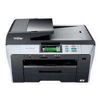
Brother DCP-6690CW User Manual (137 pages)
Copier printer
Brand:
Brother
| Category:
All in One Printer
| Size: 5.02 MB
Table of Contents
Compilation and Publication
3
Table of Contents
5
1 General Information
10
Using the Documentation
10
Symbols and Conventions Used in the Documentation
10
Accessing the Software User's Guide and Network User's Guide
11
Viewing Documentation
11
Accessing Brother Support (for Windows ® )
13
Control Panel Overview
14
LCD Screen Indications
15
Basic Operations
15
Warning Indications
16
2 Loading Paper and Documents
17
Loading Paper and Other Print Media
17
Loading Paper in Paper Tray #1
17
Loading Paper in Paper Tray #2
20
Loading Envelopes and Post Cards
23
Removing Small Printouts from the Machine
24
Printable Area
25
Acceptable Paper and Other Print Media
26
Recommended Print Media
26
Handling and Using Print Media
26
Choosing the Right Print Media
28
Loading Documents
30
Using the ADF
30
Using the Scanner Glass
31
Scannable Area
32
3 General Setup
33
Paper Settings
33
Paper Size and Type
33
Secure Paper Feed Mode for A3 Size Short Grain Paper
33
Sleep Mode
34
Beeper Volume
34
LCD Screen
35
Changing LCD Language
35
LCD Contrast
35
Setting the Backlight Brightness
35
Setting the DIM Timer for the Backlight
35
Printing Reports
36
How to Print a Report
36
4 Making Copies
38
How to Copy
38
Entering Copy Mode
38
Making a Single Copy
38
Making Multiple Copies
38
Stop Copying
38
Copy Settings
39
Changing Copy Speed and Quality
39
Enlarging or Reducing the Image Copied
39
Tray Select
40
Paper Options
40
Adjusting Brightness and Contrast
41
Sorting Copies Using the ADF
41
Making N in 1 Copies or a Poster
42
Skew Adjustment
44
Book Copy
44
Watermark Copy
45
Setting Your Favourites
46
Section III Direct Photo Printing
47
5 Printing Photos from a Memory Card or USB Flash Memory Drive
48
Photocapture Center™ Operations
48
Printing from a Memory Card or USB Flash Memory Drive Without a PC
48
Scanning to a Memory Card or USB Flash Memory Drive Without a PC
48
Using Photocapture Center™ from Your Computer
48
Using a Memory Card or USB Flash Memory Drive
48
Memory Cards or a USB Flash Memory Drive Folder Structure
49
Getting Started
50
Entering Photocapture Mode
51
Print Images
51
View Photos
51
Enhance Photos
52
Index Print (Thumbnails)
53
Printing Photos
54
DPOF Printing
54
Photocapture Center™ Print Settings
55
Print Speed and Quality
56
Paper Options
56
Adjusting Brightness, Contrast and Colour
57
Cropping
58
Borderless Printing
58
Date Print
58
Setting Your Changes as a New Default
58
Restoring All Settings to the Factory Settings
59
Scan to a Memory Card or USB Flash Memory Drive
59
Entering Scan Mode
59
How to Scan to a Memory Card or USB Flash Memory Drive
60
How to Change the File Name
61
How to Set New Default
61
How to Reset to Factory Settings
61
Understanding the Error Messages
61
6 Printing Photos from a Camera
62
Printing Photos Directly from a Pictbridge Camera
62
Pictbridge Requirements
62
Setting Your Digital Camera
62
Printing Images
63
DPOF Printing
63
Printing Photos Directly from a Digital Camera (Without Pictbridge)
64
Printing Images
64
Understanding the Error Messages
65
Section IV Software
67
7 Software and Network Features
68
A Safety and Legal
70
Choosing a Location
70
To Use the Machine Safely
71
Important Safety Instructions
76
IMPORTANT - for Your Safety
77
LAN Connection
77
Radio Interference
77
EU Directive 2002/96/EC and EN50419
78
International ENERGY STAR ® Compliance Statement
78
Legal Limitations for Copying
79
Trademarks
80
Troubleshooting and Routine Maintenance Troubleshooting
81
If You Are Having Difficulty with Your Machine
81
Copying Difficulties
83
Scanning Difficulties
83
Software Difficulties
84
Photocapture Center™ Difficulties
84
Network Difficulties
85
Error and Maintenance Messages
86
Error Animations Display
89
Document Jam
90
Printer Jam or Paper Jam
90
Routine Maintenance
93
Replacing the Ink Cartridges
93
Cannot Print
94
Cleaning the Outside of the Machine
95
Cleaning the Scanner Glass
97
Cleaning the Machine Printer Platen
97
Cleaning the Paper Pick-Up Roller
98
Cleaning the Print Head
98
Checking the Print Quality
99
Checking the Print Alignment
100
Checking the Ink Volume
100
Machine Information
101
Checking the Serial Number
101
Packing and Shipping the Machine
101
C Menu and Features
104
On-Screen Programming
104
Menu Table
104
Mode Keys
104
Menu Table
105
Network Menu
106
Print Settings
117
Entering Text
119
Advertisement
Brother DCP-6690CW Quick Setup Manual (43 pages)
Brand:
Brother
| Category:
All in One Printer
| Size: 3.61 MB
Table of Contents
Choose Your Language
3
Install the Ink Cartridges
4
Check the Print Quality
5
Set the Date and Time
6
Before You Install
8
Connect the Usb Cable
10
Connect the Power Cord
11
For USB Interface Users
12
Connect the Network Cable
15
For Wired Network Interface Users
15
For Wireless Network Interface Users
24
Before You Begin
24
Connecting the Brother Machine to the Wireless Network
26
Infrastructure Mode
26
For Windows Users
27
Wireless Network
30
Windows Vista
30
Install the Drivers & Software
34
Install Optional Applications
37
For Network Users
39
Bradmin Light Utility
39
Install the Bradmin Light Configuration Utility
39
Bradmin Light Utility (for Mac os ® X Users)
40
Restore the Network Settings to Factory Default
41
Entering Text for Wireless Settings
41
Replacement Consumables
42
Ink Cartridge
42
Share and save
Advertisement
Related Products
Brother DCP-7030
Brother DCP-J4110DW
Brother DCP-7045N
Brother DCP-1400
Brother DCP-1610WE
Brother DCP-7057R
Brother DCP-L5502DN
Brother DCPL2552DNYJ1
Brother DCP-L2551DW
Brother DCP-L3517CDW
Brother Categories
Sewing Machine
All in One Printer
Printer
Label Maker
Fax Machine
More Brother Manuals
Login
Sign In
OR
Sign in with Facebook
Sign in with Google
Upload manual
Upload from disk
Upload from URL