Brother DCP6690CW Service Manual
Hide thumbs
Also See for DCP6690CW:
- Network user's manual (175 pages) ,
- User manual (137 pages) ,
- Quick setup manual (43 pages)
Table of Contents
Advertisement
Quick Links
Download this manual
See also:
User Manual
Advertisement
Table of Contents
Troubleshooting

Related Manuals for Brother DCP6690CW


Summary of Contents for Brother DCP6690CW
-
Page 1: Service Manual
Inkjet DCP/MFC SERVICE MANUAL MODELS: DCP6690CW MFC6490CW MFC6890CDW Read this manual thoroughly before maintenance work. Keep this manual in a convenient place for quick and easy reference at all times. April 2008 SM-FAX089 8CAF11(3) Confidential... - Page 2 Specifications are subject to change without notice. Trademarks The Brother logo is a registered trademark of Brother Industries, Ltd. Brother is a registered trademark of Brother Industries, Ltd. Multi-Function Link is a registered trademark of Brother International Corporation.
- Page 3 Preface This Service Manual is intended for use by service personnel and details the specifications, construction, theory of operation, and maintenance for the Brother machines noted on the front cover. It includes information required for troubleshooting and service--disassembly, reassembly, and lubrication--so that service personnel will be able to understand equipment function, repair the equipment in a timely manner and order spare parts as necessary.
-
Page 4: How This Manual Is Organized
How this manual is organized This manual is made up of nine chapters and appendices. CHAPTER 1 PARTS NAMES AND FUNCTIONS Contains external views and names of components and describes their functions. Information about the keys on the control panel is included to help you check operation or make adjustments. - Page 5 Customizing codes customize firmware for individual models, enabling the common firmware to be used for various models. A list of EEPROM customizing codes comes with the firmware data provided by Brother Industries. Appendix 4 Firmware Switches (WSW)
- Page 6 Appendix 6 Circuit Diagrams Provides the circuit diagrams of the MJ PCB and power supply PCB. Appendix 7 Deletion of Personal Information Provides instructions on how to delete personal information recorded in the machine. Confidential...
-
Page 7: Safety Precautions
SAFETY PRECAUTIONS Symbols used in the documentation Confidential... - Page 8 Confidential...
- Page 9 Confidential...
- Page 10 viii Confidential...
- Page 11 Confidential...
- Page 12 Confidential...
- Page 13 Confidential...
- Page 14 CHAPTER 1 PARTS NAMES AND FUNCTIONS Confidential...
- Page 15 CHAPTER 1 PARTS NAMES AND FUNCTIONS This chapter contains external views and names of components and describes their functions. Information about the keys on the control panel is included to help you check operation or make adjustments. CONTENTS OUTLINE ........................ 1-1 CONTROL PANEL ....................
-
Page 16: Outline
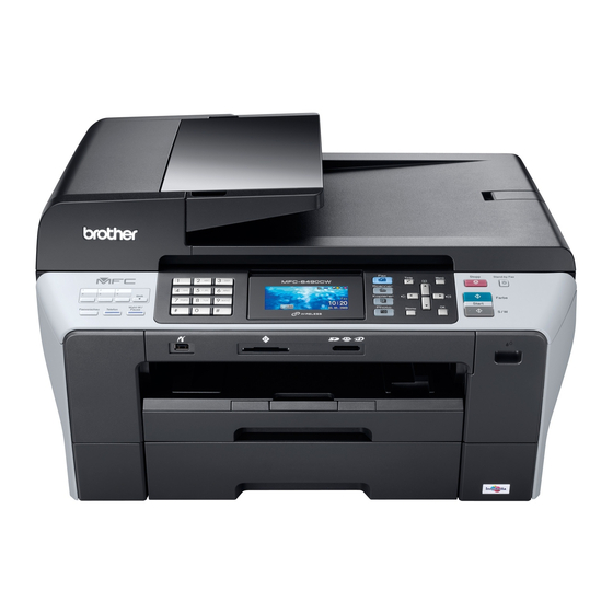
OUTLINE The illustrations in this section are based on the MFC6490CW. Front view (1) ADF & document cover ASSY (2) Control panel (10) Scanner cover (3) Ink cartridge cover (Scanner unit) (4) Media slots for PhotoCapture Center (5) Paper tray #1* (6) Paper tray #2 (7) Port for PictBridge / USB flash memory drive... - Page 17 Back view (12) USB interface connector (13) LAN cable connector (11) Outer back cover (backview) Name Description ADF: Load documents (originals) here. Documents will be fed into the machine, page by page. ADF & document cover ASSY Document cover: Open to place the document (original) on the scanner glass.
- Page 18 CONTROL PANEL DCP6690CW Confidential...
- Page 19 Confidential...
- Page 20 MFC6490CW Confidential...
- Page 21 Confidential...
- Page 22 Confidential...
- Page 23 MFC6890CDW Confidential...
- Page 24 Confidential...
- Page 25 1-10 Confidential...
- Page 26 COMBINATIONS OF TWO KEYS FOR SPECIAL FUNCTIONS The table below lists the special functions enabled by simultaneously pressing the specified combination of keys on the control panel. Special functions Combination of keys Available for: Displaying the firmware version * + # Models with numerical keypad on the control panel Scan + Stop/Exit...
- Page 27 COMPONENTS The machine consists of the following major components: ADF & document cover Control panel ASSY ASSY Scanner cover (Scanner unit) Control panel ASSY Speaker spring Edge cover R Speaker Side cover R Scanner cover damper Scanner cover support Upper cover Head/carriage unit Edge cover L Maintenance unit...
-
Page 28: Specifications
CHAPTER 2 SPECIFICATIONS Confidential... - Page 29 CHAPTER 2 SPECIFICATIONS This chapter lists the specifications of each model, which enables you to make a comparison of different models. CONTENTS GENERAL ......................2-1 2.1.1 General Specifications................2-1 2.1.2 Paper Specifications.................. 2-3 2.1.3 Printable Area.................... 2-5 SPECIFICATIONS LIST ..................2-6 Confidential...
-
Page 30: General
220 to 240 VAC 50/60 Hz Power Consumption Power save Operating Standby Off mode (sleep) DCP6690CW 26 W or less 6 W or less 4.0 W or less 0.7 W or less U.S.A./Canadian 28 W or less 6 W or less 4.0 W or less... - Page 31 Dimensions (W x D x H) DCP6690CW 540 x 488 x 323 mm (21.3 x 19.2 x 12.7 inches) 574 x 543 x 323 mm (22.6 x 21.4 x 12.7 inches) (With document stopper and paper tray flap opened) 12.7 in.
-
Page 32: Paper Specifications
2.1.2 Paper Specifications U.S.A./Canadian models European/Asian/Oceanian models Paper Type Item Paper Type Item Ledger Plain BP60PLGR (USA only) A3 Plain BP60PA3 Ledger Glossy Photo BP71GLGR A3 Glossy Photo BP71GA3 Letter Plain BP60PL100 (USA only) A3 Inkjet (Matte) BP60MA3 Letter Glossy Photo BP71GLTR A4 Plain BP60PA... - Page 33 1 Up to 100 sheets for paper of 80 g/m (20 lb) 2 Up to 250 sheets for paper of 80 g/m (20 lb) 3 BP71, 260 g/m (69 lb) paper designed for Brother inkjet machines Confidential...
-
Page 34: Printable Area
2.1.3 Printable Area Top (1) Bottom (2) Left (3) Right (4) Cut Sheet 0.12 in. (3 mm) 0.12 in. (3 mm) 0.12 in. (3 mm) 0.12 in. (3 mm) Envelopes 0.47 in. (12 mm) 0.95 in. (24 mm) 0.12 in. (3 mm) 0.12 in. -
Page 35: Specifications List
SPECIFICATIONS LIST DCP6690CW/MFC6490CW (1/8) Confidential... - Page 36 (2/8) Confidential...
- Page 37 (3/8) Confidential...
- Page 38 (4/8) Confidential...
- Page 39 (5/8) 2-10 Confidential...
- Page 40 (6/8) 2-11 Confidential...
- Page 41 (7/8) 2-12 Confidential...
- Page 42 (8/8) 2-13 Confidential...
- Page 43 MFC6890CDW (1/10) 2-14 Confidential...
- Page 44 (2/10) 2-15 Confidential...
- Page 45 (3/10) 2-16 Confidential...
- Page 46 (4/10) 2-17 Confidential...
- Page 47 (5/10) 2-18 Confidential...
- Page 48 (6/10) 2-19 Confidential...
- Page 49 (7/10) 2-20 Confidential...
- Page 50 (8/10) 2-21 Confidential...
- Page 51 (9/10) 2-22 Confidential...
- Page 52 (10/10) 2-23 Confidential...
-
Page 53: Theory Of Operation
CHAPTER 3 THEORY OF OPERATION Confidential... -
Page 54: Table Of Contents
CHAPTER 3 THEORY OF OPERATION This chapter gives an overview of the scanning and printing mechanisms as well as the sensors, actuators, and control electronics. It aids in understanding the basic principles of operation as well as locating defects for troubleshooting. CONTENTS OVERVIEW ...................... -
Page 55: Overview
OVERVIEW - Digital camera - Compact Flash (with PictBridge) - Memory Stick - SD Memory Card - USB flash memory drive - xD-Picture Card Host WLAN Control Backup Touch WLAN Color PhotoCapture panel battery interface panel interface interface Center Fax Control Section (MFC) Printer Control Section Scanner Control Section (DCP) SDAA... -
Page 56: Mechanical Components
MECHANICAL COMPONENTS This machine consists of the scanner mechanism and printing mechanism. It uses five motors (CIS motor, ADF motor, paper feed motor, ASF motor, and carriage motor), three encoders (PF encoder, ASF encoder, and CR encoder), various sensors, and two thermistors. Scanner Mechanism (Right) (Left) - Page 57 Paper pulling-in, registration, feeding and ejecting mechanisms Recording paper path (Front) (Rear) Recording paper path Recording paper path in paper tray #1* in paper tray #2 (3_02_BH9_E) DX paper tray #1 for duplex print models Duplex print mechanism (for duplex print models) (Front) (Rear) Recording paper path...
- Page 58 Scanner Mechanism - Document scanning mechanism CIS motor (See Section 3.2.1.) (stepping motor) - Automatic document feeder (ADF) ADF motor mechanism (stepping motor) Printing Mechanism - Ink supply and ink jet mechanism (See Section 3.2.2.) (See Section 3.2.2.1.) - Head maintenance mechanism (See Section 3.2.2.2.)
-
Page 59: Scanner Mechanism
3.2.1 Scanner Mechanism This mechanism consists of the automatic document feeder (ADF), document cover, and scanner unit (scanner cover). The scanner unit consists of a scanner top cover, CIS unit, CIS drive assembly, and scanner base. The detailed illustration on the next page shows the components making up the ADF: document pull-in roller, document separation roller, document feed rollers, document ejection rollers, ADF motor, document front and rear sensors, and document width sensor For further details on the sensors, see... - Page 60 Document feed rollers Document pressure roller 1 Document separation roller Document support Document pull-in roller Document ejection rollers (Right) (Left) Document path for ADF scanning Pinch rollers CIS unit ADF motor Document for flat-bed scanning Document width sensor actuator Document front sensor actuator ADF parts Document pressure bar Document rear sensor actuator...
- Page 61 The scanner mechanism offers two types of scanning: ADF scanning and flat-bed scanning. It automatically switches to the former at the start of a scan operation if the document front sensor inside the ADF detects a document. (1) ADF scanning: Document moves across stationary CIS unit Placing a document face up in the ADF activates the document front sensor, switching to ADF scanning.
-
Page 62: Printing Mechanism
3.2.2 Printing Mechanism The printing mechanism consists of the following. Ink supply and ink jet mechanism (Section 3.2.2.1) Head maintenance mechanism (Section 3.2.2.2) Carriage drive mechanism (Section 3.2.2.3) Paper pulling-in, registration, feeding and ejecting mechanisms (Section 3.2.2.4) Duplex print mechanism (Section 3.2.2.5) (for duplex print models) The ink supply mechanism supplies ink to the head/carriage unit, in which the ink jet... - Page 63 - Outer back cover (shown on page 3-41): Opening this cover allows the user to access paper jammed. It also guides paper pulled in from the paper tray into the printing section. - Paper feed roller (shown on page 3-42): This roller performs paper registration and feeds paper to the printing section precisely.
- Page 64 After the machine prints on the top face of the recording paper, the duplex print mechanism (for duplex print models) (detailed on page 3-46) drives the DX flapper in the duplex unit to switch the recording paper path and then drives the switchback roller (SB roller) to switch back the recording paper (that has just been printed on its top face and ejected temporarily to the duplex unit) toward the DX paper tray #1.
-
Page 65: Ink Supply And Ink Jet Mechanism
3.2.2.1 Ink supply and ink jet mechanism [ 1 ] Overview The ink supply and ink-jet mechanism consists of the head/carriage unit, four ink cartridges, ink refill assembly, and four ink supply tubes. The head/carriage unit scans the surface of the recording paper, jetting out ink supplied through the ink supply tubes onto the paper to produce images. -
Page 66: Features
[ 2 ] Features A distinct feature of this machine is the use of ink supply tubes between the ink cartridges and the head/carriage unit. Relieving the head/carriage unit of the task of carrying heavy ink cartridges back and forth across the page, the approach generally adopted by other ink-jet printers, offers the following advantages. -
Page 67: Head/Carriage Unit
[ 3 ] Head/carriage unit The head/carriage unit consists of a front end (ink-jet head) and a back end (damper and air vent unit) as shown below. The front end consists of metal plates laminated together and etched to form ink flow channels. Piezoelectric ceramic actuators generate the spray pressure. - Page 68 Front end Front end components and their main roles - Piezoelectric plate Applying a voltage stretches the plate, serving as the actuator for spraying ink. Consisting of thin piezoelectric plates laminated together, this plate can be driven even by a low voltage. - Filter This removes foreign materials from the ink.
- Page 69 Ink spray function The head employs drop-on-demand ink-jet printing. Print commands to the drive circuit apply a bias voltage to the layer electrodes on the piezoelectric ceramic surface stretching the elements perpendicular to that surface. Drive signals removing this voltage for specific channel electrodes allow the piezoelectric elements to return to their original shape, sucking ink into the corresponding channels*.
- Page 70 Back end Damper ASSY (Magenta) Air bubbles Left chamber Right chamber Damper ASSY (Cyan) Air bubbles Right chamber Shut-off valves Left chamber Air vent unit Damper ASSY (Yellow) Air bubbles Right chamber Left chamber Damper ASSY (Black) Air bubbles (Air vent cap) (Air vent rods) Left chamber (A part of maintenance unit)
- Page 71 Damping Without damping, ink pressure fluctuations directly affect the size of ink-jet head droplets, risking lower print quality. Each damper assembly has two chambers. The one on the right in the illustration below has a loose film across its top and serves as a damper. The film immediately flexes in and out in response to falls and rises in pressure, adjusting the chamber volume to counteract pressure fluctuations in the ink supply tubes.
- Page 72 ---------------------------------------- [ Tip: Air bubble growth ] ---------------------------------------- Liquid ink contains trace amounts of air. The amount varies with the pressure on the ink because increasing the pressure raises the ink's ability to absorb air from its surroundings and lowering the pressure forces the ink to give up some of this air. The ink pressure fluctuations caused by the piezoelectric ceramic actuators repeatedly expand and contract any air bubbles, growing them larger gradually.
- Page 73 -------------------------- [ Tip: What's so bad about air bubble growth? ] -------------------------- Pressure fluctuations do not affect the volume of a liquid (ink), but Boyle's Law says that the volume of a gas (air) varies with the pressure on it. The main issue with air bubbles in the ink flow path is their damping effect, absorbing the pressure from the piezoelectric ceramic actuators and thus degrading ink-jet performance.
-
Page 74: Ink Cartridges
[ 4 ] Ink cartridges Ink near-empty/Ink empty Filled with ink Disc valve S Sensor actuator Ink empty sensor (3_06) Disc valve D Ink cartridge features This machine uses four ink cartridges: a black one and three color ones with a slightly lower capacity. - Page 75 Ink cartridge components and their main roles - Disc valve S A plastic needle in the refill base opens this valve to supply air to the ink cartridge. Removing the ink cartridge closes this valve to prevent leakage due to ink backflow. - Disc valve D A plastic needle in the refill base opens this valve to allow ink to flow out of the ink cartridge.
- Page 76 Disc valve S Air intake port Ink empty sensor Sensor actuator Ink supply port (InkBackflowPrevention) Disc valve D Discrimination of ink cartridge type When the user is inserting an ink cartridge into the machine, a part of the cartridge interrupts the light paths of the ink cartridge detection sensor and ink empty sensor (both are photosensors of transparent type), which are mounted on the ink refill assembly as shown on the next page.
-
Page 77: Ink Refill Assembly
[ 5 ] Ink refill assembly Cartridge release levers Ink empty sensor PCB Ink refill case (3_07) Ink empty sensors Ink cartridge detection sensors Ink cartridge detection sensor PCB Ink foam case Ink foam Ink refill base foam Ink refill base (3_08) 3-23 Confidential... -
Page 78: Ink Supply Tubes
Ink refill assembly components and their main roles - Ink refill case - Cartridge release levers - Ink refill base and its foam - Ink cartridge detection sensors (on the ink cartridge detection sensor PCB) - Ink empty sensors (on the ink empty sensor PCB) - Ink foam and its case Pushing each ink cartridge into the ink refill case until it clicks secures it and forces the cartridges' ink supply port into close contact with the ink refill base to prevent ink leakage. -
Page 79: Head Maintenance Mechanism
3.2.2.2 Head maintenance mechanism [ 1 ] Overview The head maintenance mechanism, which keeps the optimum head performance, consists of the maintenance unit and the ink absorber box. (See the illustration below.) The maintenance unit has the following mechanisms. - Head capping mechanism (See page 3-28.) - Carriage lock mechanism (See... -
Page 80: Maintenance Unit Components
[ 2 ] Maintenance unit components Pump switching unit Air cap stopper (For duplex print models only) Purge gear Air vent cap Planetary arm Purge cam Cap lift cam Air vent rods Cap lift cam gear Carriage lock (Part of head cap holder) (ASF changeover Purge bevel gear... - Page 81 - Purge cam This rotating cam drives the pump switching unit, the air vent rods, and the head wiper. Each drive position of the purge cam is detected by the purge cam switch. (See Section 3.2.3.) - Pump switching unit This switches the application target of the negative pressure generated by the tube pump between the head cap for black ink, the one for color ink, and the air vent cap.
-
Page 82: Mechanisms Constituting The Head Maintenance Mechanism
[ 3 ] Mechanisms constituting the head maintenance mechanism (1) Head capping mechanism The ASF motor drives the head capping mechanism. When the power is off or the machine is not printing, this mechanism fits the head cap unit (which contains two head caps) tightly over the print head to prevent the head nozzles from drying up and to keep dust off the head nozzle surface. - Page 83 (3) Purge mechanism The paper feed motor drives the purge mechanism. The counterclockwise rotation of the paper feed motor drives the purge cam that aligns the pump switching unit with either the black or color ink drain position. Next, the paper feed motor reverses to activate the tube pump, producing negative pressure to drain the air and old ink from the head nozzles and channels into the ink absorber box.
- Page 84 (3.1) Switching pump The pump switching unit switches the application target of the negative pressure generated by the pump between the head cap for black ink, the one for color ink, and the air vent cap. When the purge cam is in a head capping position and the head cap unit fits tightly over the print head, the pump switching unit is switched to the opening tube to the atmospheric air so that the pressure in the head caps and air vent cap returns to the normal atmospheric pressure.
- Page 85 (4) Air removing mechanism Other two positions of the purge cam shift two slide cams--one for black ink, the other for color inks, producing vertical motion of a single air vent rod for black ink and three air vent rods for color ink, respectively.
- Page 86 (5) Head wiper mechanism After the purge operation, the purge cam pushes up the head wiper, wiping off any ink remaining on the head nozzle surface as the head/carriage unit moves from right to left. Purge gear (Cap lift cam gear) (ASF changeover gear) Head wiper Purge cam...
-
Page 87: And Motor Rotational Direction
[ 4 ] Power transmission route to the head maintenance mechanism and motor rotational direction This mechanism draws its power from two motors--the ASF motor (DC motor) in the right rear corner of the engine chassis and the paper feed motor (DC motor) on the left side. The ASF motor is mounted in the ASF motor holder combined with the maintenance unit. - Page 88 ASF changeover gear Cap lift cam switch Cap lift cam gear Purge cam Pump switching unit Color drain tube Purge cam switch Black drain tube Tube pump Planetary arm Opening tube to the atmospheric air Main drain tube Air vent tube (3_20) ASF motor Clutch gear R...
- Page 89 ASF motor holder Mode switching lever ASSY Switching lever spring Air cap stopper (For duplex print models only) Air vent cap Air vent rods Maintenance unit Clutch gear spring Clutch gear L Clutch gear R ASF changeover gear Cap lift cam gear Cap lift cam Carriage lock Purge gear...
-
Page 90: Purge Types, Ink Usage, Purge Counts, And Purge Codes
[ 5 ] Purge types, ink usage, purge counts, and purge codes Refer to the table given on page 9-50. [ 6 ] Ink cartridge capacities and the number of printable pages per ink cartridge Ink cartridge capacities Ink Cartridge Type Contents Usable Portion ±... -
Page 91: Carriage Drive Mechanism
3.2.2.3 Carriage drive mechanism The head/carriage unit, which integrates the print head unit and carriage, is supported and guided by the CR guide rail and CR support chassis. The CR timing belt transmits the carriage motor rotation to the head/carriage unit. Clockwise motor rotations move the head/carriage unit to the right;... - Page 92 Adjusting the print head angle relative to carriage For optimal image printing, the print head nozzle array must be perpendicular to the head/ carriage unit's line of travel. Manufacturing limitations, however, make perfect alignment impossible during mass production. The angle must be adjusted at the individual machine level. The following describes this adjustment mechanism's components and their roles.
- Page 93 Height adjustment of the head/carriage unit For optimal image printing, a pair of slider cams mounted on the head/carriage unit switches the height of the head/carriage unit against the CR guide rail and support chassis between two levels--2.3 mm (for thick paper and envelops) and 1.6 mm (for other types of paper) in order to bring the optimum distance between the head nozzle surface and paper.
- Page 94 As listed below, the printer driver on the connected PC or the paper type setting on the machine controls the slider cams to determine the height of the head/carriage unit. Adjustment for: Controlled by: Thick paper and envelopes Other types of paper Printer driver (in printing from the PC) Paper type setting (in copying and printing via PhotoCapture Center)
-
Page 95: Paper Pulling-In, Registration, Feeding And Ejecting Mechanisms
3.2.2.4 Paper pulling-in, registration, feeding and ejecting mechanisms These mechanisms are driven via a gear train by two motors--paper feed motor located on the left side of the engine chassis and ASF motor on the right side. (See the illustration on the next page.) The following illustration is a cross-sectional view of the machine viewed from the right. - Page 96 Power transmission routes of the ASF motor and paper feed motor The rotational torque of the ASF motor is transmitted to the ASF/maintenance drive gear which always meshes with the clutch gear L, as described in Section 3.2.2.2, [ 4 When the mode switching lever is in the left position (normal SF, high-speed feed, or LT mode), the clutch gear L also meshes with the ASF changeover gear which transmits the ASF motor rotation via a gear train to the paper pull-in rollers (that pull in paper from paper tray...
- Page 97 Normal SF, high-speed feed, and LT modes Normal SF mode (Paper tray #1 1st stage The ASF motor rotates clockwise (when viewed from the output gear side) and its rotational torque is transmitted to the ASF/maintenance drive gear that is always connected via the idle gear 16 to the clutch gear L.
- Page 98 LT mode (Paper tray #2) The machine has paper tray #2, from which paper is fed into the printing section in the LT mode. Just like the normal SF/high-speed feed modes, the LT mode uses the same components from the ASF/maintenance drive gear to the paper pull-in gear shaft. After the following process, the LT dedicated components are used.
- Page 99 Other controls Paper feed position and speed control A PF encoder disk with the resolution of 300 dpi (0.084 mm pitch) is mounted on the PF roller gear L. The PF encoder sensor uses it to generate a signal indicating the gear rotation speed--in other words, the paper feed roller speed--to the controller for use in controlling paper feed position and speed.
-
Page 100: Duplex Print Mechanism
3.2.2.5 Duplex print mechanism The major components of the duplex print mechanism are a duplex print unit (duplex unit), link gear holder DX ASSY (black), and link gear holder LT DX ASSY (white). As described in Section 3.2.2.4, the paper pulling-in, registration, feeding and ejecting mechanisms eject the recording paper printed on its top face. - Page 101 DX flapper drive mechanism The rotational torque of the ASF motor is transmitted to the cap lift cam gear in the maintenance unit. As shown below, the rotational torque is further transmitted via the link gear holder DX ASSY and the link gear holder LT DX ASSY to the DX gear 25/18 mounted at the right end of the duplex unit.
- Page 102 SB roller drive mechanism The rotational torque of the paper feed motor is transmitted to the paper ejection roller shaft on which the paper ejection roller SB gear is mounted. As shown below, the rotational torque is further transmitted via the SB gears A to D to the SB roller drive gear. The torque transmission to the SB roller can be disengaged by the SB clutch lever engaged with the outer profile of the DX cam.
- Page 103 Recording paper feeding/ejecting control in duplex printing In duplex printing, the machine feeds and ejects the recording paper by driving the paper pull-in rollers, paper feed roller, and SB roller. In the descriptions below, the rotational directions of those rollers are as viewed from the left side of the machine. Top-face printing The paper pull-in rollers and the paper feed roller are concurrently driven to feed the recording paper.
- Page 104 After the paper reaches the paper feed roller (rotating counterclockwise), the paper pull-in rollers keep rotating clockwise. This assures paper buckling to separate the paper from the inner chute, preventing paper from lifting from the platen. This concurrent drive continues until the leading edge of the paper comes under the star wheels on the CR support chassis.
-
Page 105: Sensors And Actuators
3.2.3 Sensors and Actuators This machine uses the following sensors and thermistors. Sensor Name Location Sensor Type Document front sensor Photosensor On the document sensor PCB in the ADF unit Document rear sensor Photosensor On the document width sensor PCB Document width sensor Photosensor in the ADF unit... - Page 106 • The head thermistor detects the temperature inside the head/carriage unit. According to the sensor information, the controller adjusts the head driver to compensate for changes in ink viscosity. • The carriage motor (CR) encoder sensor monitors the current position and speed of the head/ carriage unit.
- Page 107 Most sensors are photointerrupters consisting of a light-emitting diode and a light-sensitive transistor as shown below. The only exception is the paper width sensor, which uses reflective type. The illustration on the next page gives the sensor and actuator locations. Actuator's end Light-emitting Light-sensitive...
- Page 108 ADF & document cover ASSY Document width sensor PCB Document width sensor Document width sensor actuator Document front sensor actuator Document front sensor Document rear sensor Document rear sensor actuator Document sensor PCB (3_26) Cap lift cam switch (ASF encoder sensor PCB) CR encoder sensor ASF encoder sensor (Carriage PCB on which the...
-
Page 109: Control Electronics
CONTROL ELECTRONICS 3.3.1 Components The following illustration shows the hardware components. The corresponding wiring diagrams appear in Appendix WLAN Backup battery Speaker WLAN PCB Power supply AC line LAN I/F 4 wires used in 2-wire 5 wires used in 5-wire 5-wire connector 6-wire connector housing... -
Page 110: Troubleshooting
CHAPTER 4 ERROR INDICATION AND TROUBLESHOOTING Confidential... - Page 111 CHAPTER 4 ERROR INDICATION AND TROUBLESHOOTING This chapter details error messages and codes that the incorporated self-diagnostic functions display if any error or malfunction occurs. If any error message appears, refer to this chapter to find which components should be checked or replaced. The latter half of this chapter provides sample problems that could occur in the main sections of the machine and related troubleshooting procedures.
- Page 112 [ 3 ] Head/carriage unit drive and purge mechanisms......4-54 [ 4 ] Print head mechanism ..............4-55 [ 5 ] Duplex print mechanism..............4-56 [ 6 ] Sheet feeder (SF) mechanism ............4-56 [ 7 ] Paper feeding mechanism ..............4-57 [ 8 ] Speaker .....................
-
Page 113: Error Indication
ERROR INDICATION To help the user or the service personnel promptly locate the cause of a problem (if any), the machine incorporates the self-diagnostic functions which display error messages for equipment errors. 4.1.1 Equipment Errors If an equipment error occurs, the machine emits an audible alarm (five short beeps twice) and shows the error message on the LCD. - Page 114 [ 1 ] Error messages appearing on the LCD Confidential...
- Page 115 For MFC only Confidential...
- Page 116 For MFC only Confidential...
- Page 117 For MFC only Confidential...
- Page 118 Confidential...
- Page 119 Confidential...
- Page 120 [ 2 ] Error codes contained in "MACHINE ERROR X X" messages Using Function code 82 (described in Chapter 9, Section 9.4.27) displays the most recent error in the format of "MACHINE ERROR XX." The XX represents one of the error codes listed in this section.
- Page 121 Error Code Symptom Probable Cause Solution (Hex) The switchback paper Too much ink used for top- Pull out the DX paper tray #1, detection sensor does not face printing had made the open the DX cover, and come ON within the paper curly or wavy so that remove the jammed paper.
- Page 122 Error Code Symptom Probable Cause Solution (Hex) At the start of Too much ink used for top- Pull out the DX paper tray #1, switchback, the face printing had made the open the DX cover, and switchback paper paper curly or wavy so that remove the paper jammed near detection sensor is switchbacking the paper...
- Page 123 Error Code Symptom Probable Cause Solution (Hex) DX cam malfunction or Initialization failure during Restart the machine. DX cam switch ON/OFF powering-ON sequence detection failure when DX cam switch defective Correct the connection of the duplex printing is not in DX cam switch harness to the progress.
- Page 124 Error Code Symptom Probable Cause Solution (Hex) Not used. DX cam not driven even Initialization failure during Restart the machine. if the specified rotational powering-ON sequence torque is transmitted DX flapper drive failure due Pull out the DX paper tray #1, to foreign materials gotten open the DX cover, and into the DX flapper...
- Page 125 Error codes for all models Error Code Symptom Probable Cause Solution (Hex) Cannot identify the type Ink cartridge not loaded Reload the corresponding ink of the ink cartridge correctly cartridge. loaded because the -Ink cartridge loaded after signal values detected by the ink cartridge cover has the corresponding ink been left open for 10 min-...
- Page 126 Error Code Symptom Probable Cause Solution (Hex) Not used. Ink cartridge cover Ink cartridge cover sensor Replace the control panel PCB. opened. (carbon switch) defective Ink cartridge cover’s tab Replace the ink cartridge broken cover. Ink cartridge cover sensor Set the ink cartridge cover actuator unhooked sensor actuator into place.
- Page 127 Error Code Symptom Probable Cause Solution (Hex) Recording error related ASF encoder disk, PF Replace the ASF motor ASSY, to ASF motor, paper feed encoder disk, or CR encoder PF encoder disk, or CR motor, and carriage strip stained or scratched encoder strip.
- Page 128 Error Code Symptom Probable Cause Solution (Hex) The temperature of the Head property parameters Enter the correct parameter print head driver has incorrect in the EEPROM values. risen abnormally. Air bubbles in the head/ Perform the initial purge. The head driver chip carriage unit temperature sensor in the head driver detects...
- Page 129 Error Code Symptom Probable Cause Solution (Hex) The head drive voltage Head flat cables and Correct those flat cables. has not risen to the carriage-head flat cable not specified level. connected correctly Head/carriage unit defective Replace the carriage PCB ASSY. Replace the head/carriage unit.
- Page 130 Error Code Symptom Probable Cause Solution (Hex) The purge cam switch Planetary arm assembly not Set the maintenance unit into does not come ON at engaged correctly place. each detection point. If the planetary arm does not move smoothly, clean it. Purge cam switch harness not Correct the connection to the connected correctly...
- Page 131 Error Code Symptom Probable Cause Solution (Hex) 58, 59 Not used. Abnormal stop of purge Foreign materials in the Remove foreign materials. cam being driven machine PF encoder disk being in Replace the PF encoder disk. contact with the upper cover and deformed PF encoder PCB defective Replace the PF encoder/...
- Page 132 Error Code Symptom Probable Cause Solution (Hex) Not used. Paper width sensor Paper width sensor (media Readjust the left and right (media sensor) error. sensor) adjustment failure margins. Paper width sensor defective Replace the carriage PCB ASSY. Head flat cables broken Main PCB defective Replace the main PCB.
- Page 133 Error Code Symptom Probable Cause Solution (Hex) Fails to switch the cap Cap lift cam switch defective Replace the maintenance unit. lift cam positions. ASF encoder sensor Replace the ASF motor ASSY. defective ASF motor defective Main PCB defective Replace the main PCB. 74-79 Not used.
- Page 134 Error Code Symptom Probable Cause Solution (Hex) At the start of FAX Paper smaller than the Load the correct size of paper. message printing, the specified size loaded in the controller detects that paper tray paper is smaller than A4 Paper width sensor (media Adjust the margin for size in width.*...
- Page 135 Error Code Symptom Probable Cause Solution (Hex) Recording paper jam. Paper double feeding caused Reload paper. by incorrect loading in the (At the start of paper paper tray feeding, the registration sensor is already ON.) Bank ASSY Paper Correct Wrong Bank ASSY deformed Replace the bank ASSY.
- Page 136 Error Code Symptom Probable Cause Solution (Hex) Recording paper jam. Foreign materials in the Remove foreign materials. paper path (The registration sensor sticks to ON after Registration sensor actuator Correct the surrounding parts completion of paper caught on the surrounding on which the actuator caught.
- Page 137 Error Code Symptom Probable Cause Solution (Hex) Not used. The paper feed motor Foreign materials in the Remove foreign materials. does not rotate. machine Paper feed motor harness not Reconnect the paper feed connected correctly motor harness. Abnormal load applied to the Replace the PF-related gear(s).
- Page 138 Error Code Symptom Probable Cause Solution (Hex) 8D, 8E Not used. The paper feed motor is Software malfunction Open and close the scanner being driven and cannot cover. be stopped. Unplug and plug the AC cord. Paper feed motor harness not Correct the connection.
- Page 139 Error Code Symptom Probable Cause Solution (Hex) Not used. FAX scanning failure CIS defective Replace the scanner cover (1st time)*. (scanner unit). White reference film stained in the scanner cover FAX scanning failure (retry)*. Main PCB defective Replace the main PCB. Not used.
- Page 140 Error Code Symptom Probable Cause Solution (Hex) B0-BC Not used. Black level data error. CIS defective Replace the scanner cover (scanner unit). Main PCB defective Replace the main PCB. BE-DE Not used. DF, E0 Modem error.* SDAA chip defective Turn the machine off and then Main PCB defective Replace the main PCB.
- Page 141 Error Code Symptom Probable Cause Solution (Hex) Document removed at Document front sensor Correct the surrounding parts phase B. actuator caught on the on which the actuator caught. surrounding parts Document front sensor Replace the document sensor defective PCB. Main PCB defective Replace the main PCB.
- Page 142 4.1.2 Communications Errors (For MFC only) If a communications error occurs, the machine: emits an audible alarm (intermittent beeping) for approximately 4 seconds, displays the corresponding error message, and prints out the transmission verification report if the machine is in sending operation. 4-30 Confidential...
- Page 143 Definition of Error Codes on the Communications List (1) Calling Code 1 Code 2 Causes Wrong number called. No dial tone detected before start of dialing. Busy tone detected before dialing. 2nd dial tone not detected. No loop current detected.* Busy tone detected after dialing or called.
- Page 144 (3) Compatibility [checking the NSF and DIS] Code 1 Code 2 Causes Remote terminal only with V.29 capability in 2400 or 4800 bps transmission. Remote terminal not ready for polling. Remote terminal not equipped with password function or its password switch OFF. Remote terminal not equipped with or not ready for confidential mailbox function.
- Page 145 (4) Instructions received from the remote terminal [checking the NSC, DTC, NSS, and DCS] Code 1 Code 2 Causes Illegal coding system requested. Illegal recording width requested. ECM requested although not allowed. Polled while not ready. No document to send when polled. Nation code or manufacturer code not coincident.
- Page 146 (6) ID checking Code 1 Code 2 Causes Password plus "lower 4 digits of telephone number" not coincident. Password not coincident. Polling ID not coincident. (7) DCN reception Code 1 Code 2 Causes DCN received. (8) TCF transmission/reception Code 1 Code 2 Causes Fallback impossible.
- Page 147 (9) Signal isolation Code 1 Code 2 Causes Unable to detect video signals and commands within 6 seconds after CFR is transmitted. Received PPS containing invalid page count or block count. (10) Video signal reception Code 1 Code 2 Causes Error correction sequence not terminated even at the final transmission speed for fallback.
- Page 148 (11) General communications-related Code 1 Code 2 Causes Unable to receive the next-page data. Unable to receive polling even during turn-around transmission due to call reservation. PC interface error. Communication canceled by pressing the STOP key before establishment of FAX communication*. Communication canceled by pressing the STOP key after establishment of FAX communication*.
-
Page 149: Checking Prior To Troubleshooting
TROUBLESHOOTING 4.2.1 Introduction This section gives the service personnel some of the troubleshooting procedures to be followed if an error or malfunction occurs with the machine. It is impossible to anticipate all of the possible problems which may occur in future and determine the troubleshooting procedures, so this section covers some sample problems. - Page 150 Recording paper Check that: (1) A recommended type of recording paper is used. (2) The recording paper is not dampened. Ink cartridges (1) Check that all of four ink cartridges are loaded. Head/carriage unit (1) Repeat the purge operation (Function code 76) several times. (Refer to Chapter 9, Section 9.4.24.) (2) Clean the print surface of the head/carriage unit.
-
Page 151: Control Panel
4.2.4 Troubleshooting Based on Problem Type [ 1 ] Control panel and LCD problems Problem Check: (1) LCD shows nothing. • LCD and its flat cable • Panel-main harness • Control panel PCB • Power supply PCB • Main PCB (2) Control panel inoperative. - Page 152 [ 4 ] Paper/document feeding problems Problem Check: (1) The "Enter Fax No." message • Sensors by using Function code 32 in the maintenance mode does not appear although (Refer to Chapter 9, Section 9.4.9.) documents are set. • Document front sensor actuator •...
- Page 153 [ 5 ] Print-image problems If there is any problem with any image printed, first make a copy using the machine. If the copied image is normal, the cause of the problem may be the sending station (e.g., PC and digital camera) or the memory card inserted;...
- Page 154 Problem Action to be taken (1) Completely blank At the scanner Check that the document is placed facing in the correct direction. In ADF scanning, is the document placed face up in the document tray? In flat-bed scanning, is the document placed face down on the scanner glass? Check the following components: - Scanner cover (CIS flat cable)
- Page 155 Problem Action to be taken (4) Light At the scanner Check the following components: - Scanner cover (CIS unit) - Main PCB At the printer Check the following components: - Ink cartridges - Head/carriage unit and carriage PCB ASSY - Main PCB - Power supply PCB - Head property data (Refer to Chapter 9, Section...
- Page 156 Problem Action to be taken (7) Ink splash Printer • For duplex print models: Change the special duplex copy settings using the steps below. 1) Press Duplex Copy on the machine’s panel. 2) Press On to turn on the duplex setting. 3) Press Advanced.
- Page 157 Problem Action to be taken (9) Random missing dots Printer • Perform the purge operation (Function code 76) several times to remove dust or air bubbles from its nozzles. (Refer to Chapter 9, Section 9.4.24.) • Check the ink cartridges. If any cartridges have run out of ink, replace them.
- Page 158 Problem Action to be taken (12)Overlapping or separated lines • Adjust the paper feeding correction value of the paper feed roller with over the whole page Function code 58 in the maintenance mode. (Refer to Chapter 7, Section 7.2, [ 5 •...
- Page 159 Problem Action to be taken (16)Traces of paper pull-in rollers • Clean the paper pull-in rollers. For the cleaning procedure, refer to (for duplex print models) Chapter 8, Section 8.3 "CLEANING THE PAPER PULL-IN ROLLERS (PAPER PICK-UP ROLLERS) (FOR DUPLEX PRINT MODELS)."...
-
Page 160: Components
[ 8 ] Wireless LAN (WLAN) Problem Action to be taken (1) PC-driven printing via the Check the following: wireless LAN is impossible. - The address has not been changed at both the machine and PC. - Connection between the WLAN PCB and the main PCB - WLAN PCB [ 9 ] Others Problem... - Page 161 4.2.5 Problems Encountered Frequently in the Past This section lists the four problems most frequently encountered during on-site service in the past. - Paper jams - Error message "MACHINE ERROR 4F" - Ink-related problems - Auto document feeder (ADF) failure [ 1 ] Paper jams A paper jam may occur not only due to machine malfunction but also to the user's actions.
- Page 162 [ 2 ] "MACHINE ERROR 4F" error message The error message "MACHINE ERROR 4F" appears if the head drive voltage drops from the high to low level in an abnormally short period. The source of the problem is mainly the head/ carriage unit.
- Page 163 [ 4 ] Auto document feeder (ADF) malfunction An ADF failure may occur not only due to machine malfunction but also to the user's actions. Problems due to the user's actions Check Possible causes Problems that may result Document guides The document guides are not positioned Documents will skew.
- Page 164 4.2.6 Possible Component Defects and Resulting Problems This section lists possible component defects and what happens due to them. It also describes what happens if the necessary adjustments or data settings into the memories is not made. [ 1 ] ADF mechanism Defective component Result Error codes...
- Page 165 [ 2 ] Scanner mechanism Defective component Result Error codes CIS unit - Any of the following images may appear on the printout: BD, AF - When the power is turned on, abnormal noises will be heard from the machine. - Any of the following errors occurs: - Dark level offset data level error for scanning - Gain control data level error for scanning...
- Page 166 [ 3 ] Head/carriage unit drive and purge mechanisms Defective component Result Error codes Head/carriage unit - Any of the following images may appear on the printout: --- Carriage motor - The head/carriage unit will not be able to travel 30, 31, 32, 33 normally.
- Page 167 Defective component Result Error codes Maintenance unit - Any of the following images may appear on the printout: --- Head caps or wiper Tube pump - The tube pump will not draw out ink from the head nozzles. Purge cam switch - The purge cam switch will not detect the purge cam ON/ 50, 51, 52 OFF timing.
- Page 168 [ 5 ] Duplex print mechanism Defective component Result Error codes SB roller - Paper will not be switchbacked. - Any of the following images may appear on the printout: DX flapper - Switching between the switchback and ordinary paper 0D, 1A, 1D paths fails.
- Page 169 [ 7 ] Paper feeding mechanism Defective component Result Error codes Paper feed roller - Any of the following images may appear on the printout: --- Paper ejection roller (If the paper feed roller or paper ejection roller is defective, it is necessary to replace the engine unit.) PF encoder disk...
- Page 170 [ 10 ] PCBs Defective component Result Error codes Main PCB - No faxes will be able to be sent. (For MFC only) - No phone calls will be able to be made. - Copying will not be possible. - PC-driven printing will not be possible. - Scanning will not be possible.
- Page 171 [ 11 ] Adjustments/data in the memories Adjustment/data setting error in the Error Result Refer to: following codes components: EEPROM customizing - The machine will not work as specified - Chapter 9, Section code for that model or that shipping 9.4.22 destination.
- Page 172 CHAPTER 5 HANDLING DATA HELD IN THE MACHINE PRIOR TO REPAIR Confidential...
- Page 173 CHAPTER 5 HANDLING DATA HELD IN THE MACHINE PRIOR TO REPAIR This chapter describes how to handle data held in the machine to be repaired. At the user site, if the machine cannot print FAX data received and left in the machine due to the printing mechanism defective, the service personnel should instruct the end user to follow the transfer procedure given in this chapter to transfer the FAX data to another machine before sending the machine for repair.
-
Page 174: Transferring Received Fax Data
AT THE USER SITE 5.1.1 Transferring Received FAX Data When the machine at the user site requires to be repaired, unplugging the power cord from the electrical outlet for sending the machine for repair will lose received FAX data if left in the machine. - Page 175 (7) With the "2.ACTIVITY," "3.DOCUMENTS," "4.COM.LIST (NEW)," or "5.COM.LIST (ERR3)" being displayed in step (6), press the OK key (Photo Capture key for models without OK key). The "ENTER NO. &SET" appears. (8) Enter the telephone number of the receiver machine and press the OK key (Photo Capture key for models without OK key) again.
- Page 176 Cover page sample Title Job number Total number of pages to be transferred Station ID registered in the sender equipment FAX number of the sender equipment Telephone number of the sender equipment Transfer start date Model code Boot ROM info Program manager ROM info Main ROM info Serial number...
- Page 177 - Other data (Received fax data, ICM/OGM data, etc.) Operating Procedure (1) On the PC, create a "Brother" folder in an external memory to be used for saving backup data. (2) Switch the machine to the maintenance mode using the steps below. (Refer to...
- Page 178 The external memory is being used by another operation. Insert Card No external memory is inserted. No file - No "BROTHER" folder in the external memory - Invalid file name Card Error Failed to open the file. Machine ID Error Mismatch of serial numbers between the machine and the backup data (which is detected only in data restoration).
- Page 179 CHAPTER 6 DISASSEMBLY/REASSEMBLY AND LUBRICATION Confidential...
- Page 180 CHAPTER 6 DISASSEMBLY/REASSEMBLY AND LUBRICATION This chapter details procedures for disassembling and reassembling the machine together with related notes. The disassembly order flow provided enables you to see at a glance the quickest way to get to component(s) involved. At the start of a disassembly job, you check the disassembly order flow that guides you through a shortcut to the target components.
- Page 181 6.1.17 Paper Tray ASSY #1 (DX Paper Tray ASSY #1*) ........6-93 6.1.18 Paper Tray ASSY #2 ................. 6-94 6.1.19 Routing of the Harnesses, Flat Cables, and Ink Supply Tubes ....6-95 LUBRICATION......................6-106 Confidential...
- Page 182 DISASSEMBLY/REASSEMBLY Safety Precautions To prevent the creation of secondary problems by mishandling, observe the following precautions during maintenance work. (1) Before replacing parts or units, unplug the power cord and telephone line*. In particular, when having access to the power supply inside the machine, make sure that the power cord is unplugged from the electrical outlet;...
-
Page 183: Tightening Torque
Tightening Torque Tightening torque Location of screw Screw type Q'ty Nm (kgfcm) Grounding wires (for ADF drive unit 0.40 ±0.1 (4 ±1) Taptite, cup S M3x6 and CIS motor) 0.70 ±0.1 (7 ±1) Scanner cover (Scanner unit) Taptite, bind B M4x12 0.80 ±0.1 (8 ±1) ADF &... - Page 184 Preparation Prior to proceeding with the disassembly procedure, (1) Be sure to back up the machine information and user data into an external memory. If the main PCB is replaced, restore the backup data to the new main PCB after completion of reassembling.
- Page 185 How to Access the Target Component • On the next page is a disassembly flowchart which helps you access the target components. To remove the maintenance unit, first find it on the flowchart and note its section number (Section 6.1.16 in this case).
-
Page 186: Disassembly Flowchart
Disassembly Flowchart Disassembly/reassembly standard time (seconds) 6.1.2 6.1.3 6.1.17 6.1.1 6.1.18 Scanner cover Disassembly of ADF & document ADF & document (Scanner unit) Paper tray ASSY #1 Paper tray ASSY #2 cover ASSY cover ASSY (including ADF) 80/80 - / - 35/40 35/40 35/55... - Page 187 6.1.1 Scanner Cover (Scanner Unit) The scanner cover should be removed together with the ADF & document cover ASSY whose removal procedure is given in Section 6.1.2. The disassembly of the ADF & document cover ASSY is detailed in Section 6.1.3.
- Page 188 (2) Remove the CIS flat cable cover and the harness cover by inserting the tip of a flat screwdriver into the slots and releasing the latches. CIS flat cable cover Harness cover Latches (in the slots) Pawl Pawl ADF & document cover ASSY Scanner cover (Scanner unit) Upper cover...
- Page 189 (3) Disconnect the CIS flat cable from the main PCB, pull it to the rear through the two flat cores, and then release it from the cable guides. Unlatch the flat cores and take them out of the upper cover. Note: After disconnecting the flat cable(s), check that each cable is not damaged at its end or short-circuited.
- Page 190 (6) Release the harnesses and grounding wires from the cable guides provided at the left end of the upper cover. (7) Press the lock arm provided on the front of the scanner cover damper and release the damper from the scanner cover. Lock arm Scanner cover damper...
- Page 191 (8) At the rear of the machine, remove the two screws that secure the two scanner hinges. (9) Open the scanner cover fully and pull it upward and out of the machine. Note: Pulling up the scanner cover without fully opening it opens the scanner hinges suddenly and unexpectedly with great force.
- Page 192 Assembling Notes • Route the document sensor PCB harnesses, document width sensor harness, CIS motor harness, ADF motor harness and two grounding wires as shown below. Route the document sensor PCB harness and the document width sensor harness on this right side. Upper cover Route the bundle of the ADF motor harness and...
- Page 193 6.1.2 ADF & Document Cover ASSY (1) Insert the tip of a flat screwdriver into the slit provided in the front side of the harness support and twist it to release the harness support from the scanner cover. ADF motor harness and its grounding wire, loose grounding wire, document sensor PCB harness, and document width sensor harness Harness support...
- Page 194 (2) Turn the scanner cover right side up. (3) Remove two screws "a" from the rear of the ADF & document cover ASSY. Note: Screws "a" are a special type (M9), so take care not to lose them. (4) Open the ADF & document cover ASSY fully. Note: Lifting up the ASSY without fully opening it in step (5) opens the hinge arm L suddenly and unexpectedly with great force.
- Page 195 6.1.3 Disassembly of ADF & Document Cover ASSY Document support and document stopper (1) Open the document support, warp it slightly, and remove its front and rear bosses from the holes provided in the upper ADF chute. (2) Remove the document stopper. Boss Document support Boss...
- Page 196 ADF handle cover and ADF front cover (3) Remove two screws "c" from the ADF handle cover and take the cover off the document cover downwards. (4) Remove screw "d" from the bottom of the ADF front cover. Release the two hooks inside the ADF front cover from the upper ADF chute, then release the two holes from the bosses on the bottom of the document cover.
- Page 197 ADF rear cover (5) Pull the lock arms provided on the underside of the document cover outwards and release latch "a" of the ADF rear cover. Then release latch "b" from the document cover with the tip of a flat screwdriver and remove the ADF rear cover. Lock arms Latch "a"...
- Page 198 (7) At the front end of the document pressure roller shaft, press the front latch and remove the shaft together with the document pressure roller 1. Then remove the two spring caps and take the pressure roller springs out of the ADF cover. Document pressure roller 1 Document pressure roller shaft Spring cap...
- Page 199 Upper ADF chute and document guides (F and R) (10) Remove the nine screws from the upper ADF chute, release the latch on the bottom rear side, and lift the upper ADF chute up and off the document cover. Latch Taptite, cup B M3x10 Upper ADF chute...
- Page 200 (11) Remove the screw from the document guide gear, then take the document guide gear and its spring out of the upper ADF chute. (12) As shown below, slide each of the document guides F and R inwards ( ), pull down the bottom end ( ), slide it inwards further, and take it up ( ).
- Page 201 Lower ADF chute (13) Cut off the cable tie that binds a bundle of harnesses (ADF motor harness and its grounding wire, document sensor PCB harness, and document width sensor harness) to the document cover. (14) Remove the two screws from the lower ADF chute and take the lower ADF chute off the document cover.
- Page 202 Document feed roller (15) Lightly press the lock arms on the lower ADF chute and slide two bushings "a" on the document feed roller shaft outwards. (16) At the front end of the document feed roller shaft, squeeze the lock bushing and slide the shaft to the rear.
- Page 203 Document ejection roller ASSY (19) At each of the support plates, pull a pair of lock arms on the lower ADF chute outwards and release the support plate. (20) At the front end of the shaft of the document ejection roller ASSY, squeeze the lock bushing and slide the shaft to the rear.
- Page 204 ADF drive unit and ADF motor (22) Remove the two screws from the ADF drive unit and take it off the lower ADF chute. Lower ADF chute Taptite, cup B M3x10 (Rear) Ferrite core (6_24) ADF drive unit (23) Disconnect the ADF motor harness from the motor. (24) Release the ADF motor from the drive unit by removing the screw.
- Page 205 Document front and rear sensor actuators, document width sensor actuator, document sensor PCB, and document width sensor PCB (25) At each of the document front and rear sensor actuators and the document width sensor actuator, lightly press the corresponding lock arm, slide the actuator towards the lock arm, and remove it together with the corresponding actuator spring.
- Page 206 (26) Press the lock arm and pull the left edge of the document sensor PCB to the front and upwards to remove the PCB. Then disconnect the document sensor PCB harness from the PCB. (27) Press the two PCB supports and remove the document width sensor PCB. Then disconnect the document width sensor harness from the PCB.
- Page 207 Document pressure bar (28) Turn the lower ADF chute upside down. (29) Pull either one of the lock arms on the underside of the lower ADF chute inwards and release the document pressure bar. The pressure bar spring also comes off. White reference film Document pressure bar Spring...
- Page 208 Assembling Notes • When mounting the lower ADF chute on the document cover, turn the planetary arm clockwise (viewed from the rear) to put the planetary gear in the upper position as shown on page 6-23. • Route the document sensor PCB harness, document width sensor harness, and ADF motor harness through the cable guides on the lower ADF chute as shown below.
- Page 209 • After mounting the lower ADF chute on the document cover, be sure to route a bundle of harnesses (document width sensor harness, document sensor PCB harness, and ADF motor harness and its grounding wire) on the underside of the document cover and secure the bundle with a cable tie as shown below.
- Page 210 6.1.4 Edge Covers L and R, Scanner Cover Support, and Damper (1) At the left end of the machine, remove the four screws from the edge cover L and lift it up together with the scanner cover support and damper. (2) At the right end of the machine, remove the three screws from the edge cover R and lift it Taptite, bind B Edge cover R...
-
Page 211: Control Panel Assy
6.1.5 Control Panel ASSY Models without touch panel (1) Remove the four screws from the control panel ASSY. (2) Pull up the rear end of the control panel ASSY and turn it up slightly. Note: Do not pull the control panel ASSY away from the machine since it is connected to the machine with harnesses. - Page 212 Models with touch panel (1) Remove the four screws from the control panel ASSY. (2) Pull up the rear end of the control panel ASSY and turn it up slightly. Note: Do not pull the control panel ASSY away from the machine since it is connected to the machine with harnesses.
-
Page 213: Disassembly Of Control Panel Assy
6.1.6 Disassembly of Control Panel ASSY (The control panel ASSY contains the scanner cover sensor actuator and ink cartridge cover sensor actuator.) Models without touch panel (1) Place the control panel ASSY upside down. (2) Release the three latches "x" and remove the control panel PCB ASSY (consisting of two PCBs). - Page 214 (6) Remove the two screws from the control panel base. (7) Release the seven latches and remove the control panel plate from the control panel base. Note: Take care not to drop the color LCD unit. (8) Take the color LCD unit out of the control panel base. Note: The latch spring may pop out of the control panel base.
- Page 215 Models with touch panel The illustrations in this section are based on the DCP6690CW. (1) Release four latches "a" and remove the EX plate (see the illustration on the next page). (2) Place the control panel ASSY upside down. (3) Release the panel-main harness and touch panel harness from the cable guides.
- Page 216 (8) Remove the two screws from the control panel base. (9) Release five latches "b" and remove the panel plate from the control panel base. Note: Take care not to drop the color LCD unit. (10) Take the color LCD unit out of the control panel base. Note: The latch spring may pop out of the control panel base.
- Page 217 Assembling Notes • For MFC: When attaching a new LCD back film on the control panel base, face the black side of the film upwards. • Before mounting the color LCD unit onto the control panel base, set the latch spring with its convex section facing up, fitting its hole and cutout over the front and rear bosses of the control panel base, respectively.
- Page 218 - There is a danger of explosion if the battery is incorrectly replaced. - When replacing the battery, use the spare part authorized by Brother Industries. - Batteries used should be disposed of in accordance with the local codes and regulations.
- Page 219 (2) Remove the screw from each of the side covers L and R and take those covers off. Upper cover Side cover R Taptite, bind B M4x12 Hooks Side cover L Lower cover LT cover (6_33) 6-38 Confidential...
- Page 220 (3) Disconnect the speaker harness from the main PCB and release it from the cable guides provided on the upper cover. (4) Remove the speaker spring (wire spring) and take the speaker out of the pocket provided on the upper cover. Speaker spring Speaker Upper cover...
- Page 221 (5) Open the outer back cover. (6) Open the ink cartridge cover. (7) Remove the six screws (five "a" and one "b" screws) from the upper cover. (8) Lift the upper cover up and off the lower cover. Note: Do not put your hands into the opening above the platen (shown below). Doing so may damage or stain the CR encoder strip inside.
- Page 222 (9) Place the upper cover upside down. (10) Release the rear end and the loop of the encoder guard spring from the spring guide and boss on the upper cover, respectively. (11) Unhook the encoder guard spring from the encoder guard film. (12) Slide the film inwards, turn it to the front by 90°, and release the opposite end (no spring) of the film from the boss on the upper cover.
- Page 223 Assembling Notes • When mounting the upper cover: - Make sure that the outer back cover and the ink cartridge cover are not mounted. - Make sure that the head/carriage unit is placed in the head capping position (home position). This prevents the ink supply tubes from getting crushed between the upper and lower covers.
- Page 224 6.1.8 Ink Cartridge Cover, Media Module Cover, Front cover, and WLAN PCB (1) Open the ink cartridge cover fully, warp its center upward as shown below to release the left boss from the lower cover, and then remove the ink cartridge cover. (2) Unlatch the media module cover from the lower cover and pull it out to the front.
- Page 225 (5) Release the two latches on the front cover and take out the WLAN PCB. WLAN PCB Linear bosses WLAN PCB harness Latch Latch Front cover (6_38) Assembling Notes • When mounting the front cover and WLAN PCB onto the lower cover, route the WLAN PCB harness as shown on the previous page.
-
Page 226: Main Pcb
6.1.9 Main PCB Caution: Before replacing the main PCB, make sure that the machine information has been backed up in an external memory. Failure to back up the machine information requires the ink absorber box and flushing box to be replaced after replacement of the main PCB. For detailed backup and restoration procedures, refer to Chapter 9, Section 9.4.10 "Backup of Machine Information (Function code 46) (User-accessible)."... - Page 227 *1 For models destined for countries except Japan *2 For Japanese models *3 For duplex print models DCP6690CW (Document sensor PCB harness) Head flat cable 3 (11-wire) (5-wire) Head flat cable 1 (13-wire) Carriage motor harness (2-wire) For debugging at...
- Page 228 (2) Remove the three screws (two "a" and one "b" screws) from the main PCB shield and lift it For MFC only Main PCB shield "a" "a" "b" ASF encoder harness Main-MJ (EXT) harness* Purge cam switch harness Main-MJ (LINE) SDAA Cap lift cam switch harness harness*...
- Page 229 (3) For MFC: Disconnect the main-MJ (EXT) harness from the main PCB and release it from the cable guides provided on the SDAA enclosure. (4) For MFC: Unlatch the SDAA enclosure by pinching its right and left sides and remove it from the main PCB.
- Page 230 Assembling Notes • If you replace the main PCB, you need to load programs onto the flash ROM, restore the machine information that has been backed up in an external memory (refer to Chapter 9, Section 9.4.10), and make specified adjustments of various settings (refer to Chapter 7, Section 7.3).
- Page 231 6.1.10 Outer and Inner Back Covers*, LT cover, and LT Paper Pull-in Roller ASSY * Inner back cover DX for duplex print models (1) Open the outer back cover. Pull either the left or right end of the outer back cover outwards and downwards and release the corresponding boss from the LT cover.
- Page 232 (3) Remove the six screws from the lower cover to separate it from the LT cover. Taptite, bind B M4x12 Lower cover LT cover (6_43) 6-51 Confidential...
- Page 233 (4) Remove the four screws and take the LT frame together with the LT paper pull-in roller ASSY out of the LT cover. (5) Remove the four bottom rubbers from the LT cover. Taptite, cup B M3x10 LT paper pull-in roller ASSY LT frame Take care not to lose...
- Page 234 6.1.11 MJ/PS Shield Unit (MJ PCB* and Power Supply PCB) (1) If the main PCB shield frame has not been removed, disconnect the power supply harness, main-MJ (LINE) harness* and main-MJ (EXT) harness* from the main PCB, then remove screw "d" (shown on page 6-48) from the main PCB shield frame.
- Page 235 (4) Unlatch the power cord bush and pull it up from the AC cord holder. Then release the power cord from the cable guides provided on the AC cord holder (shown on page 6-56). For 200 V series Remove screw "h" and remove the power inlet together with its bracket. Release the power cord from the cable guides.
- Page 236 Assembling Notes * For MFC only • Before mounting the MJ shield, route the main-MJ (LINE) and (EXT) harnesses* through the cable guide provided on the MJ PCB insulator*. (See the previous page.) • Route the power cord through the PS PCB insulator (see below) and the cable guides provided on the AC cord holder (see the next page).
- Page 237 Top view Ferrite core MJ PCB * Main-MJ (EXT) harness (black) * Cable guides on the AC cord holder Main-MJ (LINE) harness (yellow) * Power cord Cable guide on the PS PCB insulator MJ PCB insulator * Power supply PCB Route the power cord under this tab.
- Page 238 • When mounting the MJ/PS shield unit onto the lower cover, route the power supply harness through the U-shaped cutout (shown on page 6-53) provided in the lower MJ/PS shield. After mounting the MJ/PS shield unit, route the power supply harness through the channel and route the main-MJ (EXT) harness and main-MJ (LINE) harness on the left side of the...
- Page 239 6.1.12 Head/Carriage Unit and Ink Refill ASSY During disassembly jobs, except when removing the ink refill ASSY or engine unit (including the maintenance unit), leave the head/carriage unit in the machine. Before removing the head/carriage unit, ink refill ASSY or engine unit, you need to remove all four ink cartridges and set the protective part instead (see page 6-3).
- Page 240 CR encoder strip (1) While lightly pushing the CR encoder strip support on the left end of the engine unit inwards, unhook the right end of the CR encoder strip from the hook ( ) (2) Slide the CR encoder strip to the left ( ) and out of the head cover. At the left end of the CR encoder strip, align the rectangular hole in the strip with the boss of the strip support ( ) and take the strip off.
- Page 241 Head cover (6) Move the head/carriage unit to position "P" (shown below) by hand. Note: If the head/carriage unit does not move, rotate the ASF/maintenance drive gear counterclockwise (viewed from the left) by hand to unlock the head/carriage unit and move it to position "P."...
- Page 242 Carriage PCB ASSY (carriage PCB with head flat cables) (8) Unlock the connector on the carriage PCB and disconnect the carriage-head flat cable. Note: After disconnecting the flat cable, check that it is not damaged at its end or short- circuited.
- Page 243 Head joint, ink refill ASSY, and ink cartridge detection sensor PCB (12) Pull out the joint leaf spring to the right to release the head joint. (13) Pull the head joint up and off the head/carriage unit. Remove the head joint rubber (that is a part of the head/carriage unit but may come off with the head joint) and put it on a clean vinyl sheet while taking care not to contaminate it.
- Page 244 (14) Take out the ink supply tubes routed on the lower cover. (15) If the main PCB has not been removed, disconnect the ink cartridge detection sensor harness and the ink empty sensor harness from the main PCB. (16) Disconnect all of the harnesses. Lift the ink refill ASSY up and out of the lower cover. Note: On the back of the ink refill ASSY is an ink foam that may be stained with ink.
- Page 245 (17) Remove the screw from the ink cartridge detection sensor PCB and lift it up. Taptite, cup B M3x8 Ink cartridge detection sensor PCB Ink cartridge detection sensor harness Ink empty sensor harness Ink refill ASSY (6_56) 6-64 Confidential...
- Page 246 Head/carriage unit and CR timing belt Note: During the removal or installation of the head/carriage unit, take care not to contaminate the PF encoder disk with ink or grease. (18) While pressing the idle pulley holder to the right, remove the CR timing belt from the carriage motor pulley and idle pulley.
- Page 247 (22) A head/carriage unit is assigned a property code that represents the properties unique to that head/carriage unit. The property code is printed on head property labels--bar code label and QR code label, each of which is attached to the lower cover and carriage-head flat cable, respectively.
- Page 248 Note: When storing the head/carriage unit for a long period, be sure to put an air buffer cap on the head/carriage unit and store the unit in the head casing, as shown below. Leaving the head/carriage unit out of the casing will cause the head nozzles and ink supply ports to dry up, resulting in a damaged head.
- Page 249 • Before mounting the head/carriage unit on the engine unit, be sure to move the front and rear slider cams to the rightmost position to prevent them from scratching or damaging the PF encoder disk. Rear slider cam Head/carriage unit Front slider cam (6_60) •...
- Page 250 Routing the Head Flat Cables When Mounting the Carriage PCB ASSY 1) Mount the carriage PCB on the head/carriage unit (see page 6-61). 2) On the head/carriage unit, route the head flat cables through the cable guide and fit the hole in the film over the boss as shown below.
- Page 251 • After making sure that the ink supply tubes are routed between the tube/cable guide and the lower cover, pass the ink supply tubes through the bent section of the tube support wire as shown below. (Front) Tube guide Sponge Tube/cable guide Tube support plate Lower cover...
- Page 252 6.1.13 Ink Absorber Box, Ink Absorber Felt, and PF Encoder Disk Note: Do not remove the ink absorber box unless it needs to be replaced. Note: If the main PCB is replaced without backing up the machine information, the ink absorber box (and flushing box) should also be replaced.
- Page 253 (5) Peel off the PF encoder disk from the PF roller gear L only when it should be replaced. Note: Once removed, the PF encoder disk will become unusable and a new disk will have to be put back in. Note: Remove any adhesive remaining left on the PF roller gear L.
- Page 254 6.1.14 Duplex Unit (for duplex print models) (1) To remove the DX inner cover R from the internal right end of the lower cover, press the two hooks to the rear to release the front end from the lower cover, and take it out of the machine.
- Page 255 (3) To remove the DX spring lock that secures the right end of the DX unit, press the rib and pull out the DX spring lock. (4) To remove the DX spring lock that secures the left end of the DX unit, first release the two harnesses (switchback paper detection sensor harness and DX cam switch harness) from the cable guide provided on the internal left end of the lower cover.
- Page 256 Assembling Notes When mounting the duplex unit on the lower cover, follow the steps below. 1) Bring the duplex unit inside the lower cover, with the left end first. Fit the left and right supports over the paper ejection roller shaft and fit the metal hooks into the openings provided in the lower cover.
- Page 257 Viewed from the top (Rear) Cable guide Cable guide DX cover sensor harness* Carriage motor harness ASF encoder harness ASF motor harness Cap lift cam switch harness Ferrite cores Purge cam (Right) switch harness (6_Duplex_5) * For duplex print models 6-76 Confidential...
-
Page 258: Engine Unit And Flushing Box
6.1.15 Engine Unit and Flushing Box During disassembly jobs, except when removing the ink refill ASSY or engine unit (including the maintenance unit), leave the head/carriage unit in the machine. Before removing the head/carriage unit, ink refill ASSY or engine unit, you need to replace all four ink cartridges with the protective part (see page 6-3). - Page 259 (4) Take the paper feed motor harness and PF encoder/registration sensor harness out of the harness guides provided on the lower cover. (5) Lift the engine unit up and out of the lower cover in the direction of the arrow shown below, holding the inner chute located beneath the CR guide rail.
- Page 260 Assembling Notes • Before mounting the engine unit on the lower cover, set the chassis support. • Before mounting the engine unit on the lower, make sure that the PF encoder/registration sensor harness is routed through the cable guides on the inner chute as shown on the next page page 6-89.
- Page 261 PF encoder disk Registration sensor PCB CR guide rail Paper feed motor harness Lower cover PF encoder sensor (Left) wires (4-wire) PF encoder/ (Rear) registration sensor harness (7-wire) Registration sensor wires (3-wire) ASF motor ASF encoder harness ASF motor harness Cable guides (Rear) Hook...
- Page 262 6.1.16 Components on the Engine Unit (Earth spring, Link gear holder DX ASSY , Maintenance unit, ASF motor , Carriage motor, Star wheel holder, Paper ejection roller, Platen, Inner chute ASSY, Sub inner back cover, PF encoder/registration sensor harness unit, Paper pull-in rollers) *1 For duplex print models *2 ASF motor: Auto Sheet Feeder motor Earth spring...
- Page 263 Link gear holder DX ASSY (for duplex print models) (2) If the ink absorber box has not been removed, pull out the main drain tube from the ink absorber box. Note: Pinch the end of the main drain tube with a clip in order to prevent drained ink from leaking and the machine from getting stained with leaked ink.
- Page 264 Maintenance unit (5) Release the right end of the switching lever guide from the maintenance unit and remove it. (6) Remove the three screws in the order of (as shown below) from the maintenance unit and detach the maintenance unit from the engine unit. Remove these screws in the order of .
- Page 265 ASF motor (7) Unlatch the shaft holder and remove it from the maintenance unit. (8) Remove the ASF/maintenance drive gear and the idle gear 16. (9) Remove the ASF motor from the maintenance unit by removing the two screws. (10) Disconnect the ASF motor/encoder harness from the ASF motor. Shaft holder Latch Idle gear 16...
-
Page 266: Carriage Motor
Carriage motor (11) Remove the carriage motor from the engine unit by removing the two screws. Screw, bind M3x6 CR guide rail CR support chassis (Front) Carriage motor (6_72) 6-85 Confidential... - Page 267 Star wheel holder (12) Remove two CR frame springs from the CR support chassis. (13) Remove the link gear holder LT ASSY* from the engine unit by removing the screw. Take care not to drop the gear 15 from the link gear holder LT ASSY*. (14) Lift up the CR support chassis.
- Page 268 Platen (16) Release the PF timing belt from the paper ejection roller gear. (17) Pull the lock arm of the bushing at each end of the paper ejection roller outwards and turn it upright. (18) Lift the paper ejection roller and remove the platen from the engine unit. Paper ejection roller Lock arm of bushing Platen...
- Page 269 Inner chute ASSY, sub inner back cover, registration sensor actuator, and PF encoder/ registration sensor harness unit* * The PF encoder/registration sensor harness unit consists of a PF encoder PCB, registration sensor PCB, and PF encoder/registration sensor harness. (19) Release the three latches of the inner chute ASSY from the engine unit. First pull and release the rightmost latch (viewed from the rear) and then the remaining two ones.
- Page 270 (21) Turn the registration sensor actuator in the direction of the arrow shown below and take it off the inner chute ASSY. The sensor actuator spring comes off. (22) Take the registration sensor PCB out of the support arms. Note: The registration sensor PCB and the PF encoder PCB are assembled with their harnesses.
- Page 271 (23) While pressing down the boss that fits in the oval hole provided on the CR guide rail, slide the sub inner back cover to the right (viewed from the rear) to release the four hooks from the square holes of the CR guide rail and remove it. Engine unit Boss of lock arm Hooks...
- Page 272 Paper pull-in rollers R and L, and ASF gear shaft outer (26) Pull the pawl outwards and remove the paper pull-in roller R. Then pull out the paper pull- in roller L while turning it. The paper pull-in gear also comes off. (27) Remove the ASF idle gear holder from the right side of the engine unit.
- Page 273 Assembling Notes • Before mounting the paper pull-in roller L, apply the specified lubricant to the specified points, referring to Section 6.2. • When attaching the PF encoder disk to the PF roller gear L, using a spatular tool makes the job easier.
- Page 274 6.1.17 Paper Tray ASSY #1 (DX Paper Tray ASSY #1*) * For duplex print models (1) Pull the four lock arms on the rear of the paper tray #1 (DX paper tray #1*) outwards and release the four latches of the bank ASSY. Then pull the bank ASSY up and out of the paper tray #1 (DX paper tray #1*).
- Page 275 6.1.18 Paper Tray ASSY #2 (1) Place the paper tray ASSY #2 upside down. (2) Out of the four pawls of LT bank ASSY, first release the two at both ends. Then, while pulling up the right (or left) lock arm slightly with the edge of a scale or the like, release the right inside (or left inside) pawl of the LT bank ASSY from the paper tray #2.
- Page 276 6.1.19 Routing of the Harnesses, Flat Cables, and Ink Supply Tubes Routing A: Document sensor PCB harness, document width sensor harness, CIS motor harness, ADF motor harness and grounding wires on the upper cover Route the document sensor PCB harness and the document width sensor harness on this right side.
- Page 277 Routing B: Document sensor PCB harness, document width sensor harness, ADF motor harness and grounding wires on the lower ADF chute On the lower ADF chute Document width sensor PCB Document width sensor harness Document width sensor actuator Document front Cable sensor actuator guides...
- Page 278 Routing C: Panel-main harness on the control panel ASSY (for models with touch panel) Touch panel harness Panel-main harness Control panel PCB ASSY Cable guides Control panel base Grounding wire LCD flat cable (6_32_1_DCP) Routing D: Battery harness (for models with backup battery) and speaker harness Battery harness* and speaker harness on the upper cover * For models with backup battery Backup battery*...
- Page 279 Speaker harness Speaker Speaker harness Upper cover Cable guides Openings (6_36_1) Routing E: WLAN PCB harness WLAN PCB harness Slit Latch Cover arm Boss Boss Ink cartridge cover Media module cover Latch Lower cover Front cover Retainers (6_37) 6-98 Confidential...
- Page 280 Routing F: Carriage motor harness, ASF motor harness, paper feed motor harness, PF encoder/registration sensor harness, power supply harness, main-MJ (EXT) harness* , main-MJ (LINE) harness* , DX cam switch harness* , and switchback paper detection sensor harness* on the lower cover *1 For MFC only *2 For duplex print models On the SDAA enclosure*...
- Page 281 Routing G: Power supply harness, power cord, main-MJ (LINE) harness*, main-MJ (EXT) harness* in the MJ/PS shield unit * For MFC only PS PCB insulator Cable guide on the MJ PCB insulator* Power supply PCB Main-MJ (EXT) harness (black)* Main-MJ (LINE) harness (yellow)* Lower MJ/PS shield Power supply harness...
- Page 282 Top view Ferrite core MJ PCB * Main-MJ (EXT) Cable guides harness (black) * Main-MJ (LINE) harness (yellow) * Power supply shield Cable guide on the MJ PCB insulator * Power cord Power supply PS PCB insulator harness Power supply PCB Route the power cord under this tab.
- Page 283 Routing H: Ink supply tubes (Front) Tube guide Sponge Tube/cable guide Tube support plate Lower cover Bent section of tube support wire Magenta Tube support wire Cyan Yellow Black (6_64) 6-102 Confidential...
- Page 284 Routing I: Head flat cables Cable guides Tube/cable guide Lower cover Head flat cables Cable guide Tube support plate Tube support wire (6_63_1) Routing J: DX cover sensor harness*, purge cam switch harness, cap lift cam switch harness, carriage motor harness, and ASF motor/encoder harness on the lower cover * For duplex print models Viewed from the top...
- Page 285 Routing K: PF encoder/registration sensor harness On the inner chute ASSY Inner chute ASSY Cable guide PF encoder/registration sensor harness Cable guide (6_74_1) On the lower cover PF encoder disk CR guide rail Registration sensor PCB Paper feed motor harness Lower cover PF encoder sensor (Left)
- Page 286 Routing M: Harnesses, flat cables and ink tubes on the lower cover *1 For MFC only *2 For duplex print models Top view (Lower cover) Ink supply tubes Head flat cables Paper feed motor harness Carriage motor harness ASF motor harness PF encoder/ registration sensor harness...
- Page 287 LUBRICATION Apply the specified lubricants to the lubrication points as shown below. Lubricant type No. of Lubricant amount Lubrication points (Manufacturer) points per point Permalub BAN-5 Head/carriage unit 1 mm diameter ball (Nippon Koyu) Motor plate and CR guide rail (bottom 1 mm diameter ball edges) Switching lever guide...
- Page 288 Motor plate and CR guide rail (bottom edges) Apply a 1 mm diameter ball of grease (Permalub BAN-5) to the lubrication points below. Viewed from the bottom CR support chassis Motor plate 34+1 19+1 (Right) 42+1 (mm) CR guide rail (6_86) Switching lever guide Apply a 3 mm diameter ball of grease (Permalub BAN-5) to the lubrication point below.
- Page 289 CR guide rail and CR support chassis (upper face) Apply a 2 mm diameter ball of grease (FLOIL BG1319) to each of the 22 lubrication points below. Lubrication procedure (1) Move the head/carriage unit to the left end of its travel and hit it against the stoppers provided at the left end of the CR guide rail and support chassis.
- Page 290 CR support chassis (front and rear sides of upright rear edge) Apply a 2 mm diameter ball of grease (FLOIL BG1319) to each of the 28 lubrication points (front and back surfaces of the rear vertical edge of CR support chassis) as shown below. Head/carriage unit CR support chassis (Front)
- Page 291 Paper pull-in idle gear and paper pull-in roller L Apply a 3 mm diameter ball of grease (Molykote EM-30LP) to the lubrication point on the paper pull-in idle gear as shown below. After applying the grease at the center of a gear teeth, rotate the gear until the lubrication point is hidden by the adjacent gear, taking care not to touch the paper pull-in rollers.
- Page 292 CHAPTER 7 ADJUSTMENTS AND UPDATING OF SETTINGS, REQUIRED AFTER PARTS REPLACEMENT Confidential...
- Page 293 CHAPTER 7 ADJUSTMENTS AND UPDATING OF SETTINGS, REQUIRED AFTER PARTS REPLACEMENT This chapter details adjustments and updating of settings, which are required if the head/carriage unit, main PCB and some other parts have been replaced. CONTENTS PREPARATION ...................... 7-1 7.1.1 Requirements ....................
- Page 294 [ 13 ] Check LCD operation and specify the LCD type (Function code 12) ................7-35 [ 14 ] Adjust the touch panel (Function code 78) (For models with touch panel) ............7-35 [ 15 ] Get EEPROM data (incl. MAC address) from the WLAN PCB (For wireless LAN-enabled models)..........
- Page 295 Before proceeding to perform any adjustments or update any settings, you need the executables, data files, spare parts and supplies (provided by Brother Industries) and must set up your PC. Note: Before starting any operation involving printing of check patterns, be sure to set A4-size recording paper.
- Page 296 Spare Parts and Supplies Required for Adjustments and Updating of Settings Recording paper Ink cartridges Protective part (A4-size) Head/carriage unit, Engine unit √ √ √ (Section 7.2) √ √ Main PCB (Section 7.3) ADF unit, ADF-related parts √ √ (Section 7.4) Ink absorber box, Flushing box (Section...
- Page 297 You will have to replace the main PCB and load programs to a new PCB. Preparation You need the Brother Maintenance USB Printer driver and filedg32.exe (provided by Brother Industries). Save them in an arbitrary folder in your PC.
- Page 298 (5) Connect the machine to your PC using the USB cable. The following window appears. (6) The following screen appears, indicating the detection of new hardware device by the system. Select "No, not this time." And click Next. (7) Select "Install the software automatically (Recommended)" and click Next. Confidential...
- Page 299 (8) Alert warning message of WHQL appears. Click Continue Anyway to proceed. Confidential...
- Page 300 Click Finish to return. NOTE: In order to check whether the printer driver is successfully installed, click Start | Settings | Printers to call up the Printers window. Then, check that the Brother Maintenance USB Printer icon is shown.
- Page 301 IF YOU REPLACE THE HEAD/CARRIAGE UNIT OR ENGINE UNIT [ 1 ] Update the head property information stored in the EEPROM on the main PCB (1) Make sure that the machine's power cord is unplugged from an electrical outlet. If the machine is connected to a PC, unplug the USB cable. (2) Switch on the PC.
- Page 302 (6) On the PC, run the ID/head property setup utility (brusbsn.exe) in the folder created. The following window appears. (7) On the model menu, click BH9. Confidential...
- Page 303 (8) In Port on the BrUsbSn screen, select the port number assigned to the Brother Maintenance USB Printer. If the port number is unknown, follow steps 1) through 4) below. 1) Click Start | Settings | Printers. The Printers window appears as shown below.
- Page 304 The Brother Maintenance Printer Properties window appears as shown below. 4) Click the Ports tab. In this example, the port number assigned to the Brother Maintenance USB Printer is USB001. (9) In the Head Info. box on the BrUsbSn screen...
- Page 305 [ 2 ] Clean the new head/carriage unit (Function code 76) (1) Open the ink cartridge cover, set new ink cartridges into the ink refill ASSY, and close the ink cartridge cover. (2) Carry out a purge operation (with function code 76) using the steps below. (See Chapter 9, Section 9.4.24.)
- Page 306 [ 3 ] Print out a test pattern (Function code 09) To check that the head/carriage unit normally sprays ink droplets from all head nozzles, print out a test pattern with function code 09 (see Chapter 9, Section 9.4.4) with the following steps. Before starting the operation below, be sure to set A4-size paper in the paper tray for printing check patterns.
- Page 307 (1) Run "filedg32.exe" in the folder created. The Filedrgs window appears as shown below. (2) Drag and drop the "incline.prn" icon onto the Brother Maintenance USB Printer driver icon in the Filedrgs window shown above. The machine displays the "RECEIVING DATA" on the LCD and prints out the "Incline Adjust"...
- Page 308 Head Positioning Test Pattern 7-14 Confidential...
- Page 309 (4) Move the head/carriage unit to the center of its travel with function code 63 (see Chapter 9, Section 9.4.17) using the following key operation. Models with numerical keypad on the control panel: Press the 6, 3, and Black Start (Mono Start) keys in this order to display "START 63?"...
- Page 310 The Filedrgs window appears as shown below. For the paper feed roller adjustment using paper tray #1* (2) Drag and drop the "pfadj.prn" onto the Brother Maintenance USB Printer driver icon in the Filedrgs window shown above. The machine displays the "RECEIVING DATA" on the LCD and prints out "PF adjust check"...
- Page 311 For the paper ejection roller adjustment using paper tray #1* (7) On your PC, drag and drop the "exitadj.prn" onto the Brother Maintenance USB Printer driver icon in the Filedrgs window.
- Page 312 (15) To select the paper feed roller adjustment using paper tray #2, press the 1 key. The "PFLT NO+0" appears on the LCD. (16) Perform the same operation as in step (5) and (6). For the paper ejection roller adjustment using paper tray #2 No adjustment is needed.
- Page 313 Paper Feeding Check Pattern for the Paper Feed Roller (Paper Tray #1*) DX paper tray #1 for duplex print models 7-19 Confidential...
- Page 314 Paper Feeding Check Pattern for the Paper Ejection Roller 7-20 Confidential...
- Page 315 Paper Feeding Check Pattern for the Paper Feed Roller (Paper Tray #2) 7-21 Confidential...
- Page 316 [ 6 ] Align vertical print lines (Function code 65) Before starting the operation below, be sure to set A4-size paper in the paper tray for printing check patterns. (1) Press the 6, 5 and 1 keys in this order. The machine prints out three sets of vertical alignment check patterns in monochrome for 450 dpi, 600 dpi, and 1200 dpi (see below and the next page), each of which consists of #0 through #8 blocks.
- Page 317 Vertical Alignment Check Patterns (2/2) 7-23 Confidential...
- Page 318 The Filedrgs window appears as shown below. Left and right margin adjustment (2) Drag and drop the "media.prn" onto the Brother Maintenance USB Printer driver icon in the Filedrgs window shown above. The machine displays the "RECEIVING DATA" on the LCD and prints out the "MEDIA CHECK"...
- Page 319 Bottom margin adjustment (11) Drag and drop the "bottomadj.prn" onto the Brother Maintenance USB Printer driver icon in the Filedrgs window shown on the previous page. The machine displays the "RECEIVING DATA" on the LCD and prints out the "BOTTOM Adjust"...
- Page 320 (14) To adjust the bottom margin, enter the measured value (in units of 0.1 mm) multiplied by In this example, the bottom margin measured in step (12) is 3.1 mm, so press the 3, 1, and OK keys. Upon completion of the entry, the machine automatically returns to the initial stage of the maintenance mode.
- Page 321 Left and Right Margin Check Pattern 7-27 Confidential...
- Page 322 Bottom Margin Check Pattern 7-28 Confidential...
- Page 323 7.1.1. The Filedrgs window appears as shown below. (2) Drag and drop the "qualbh9.prn" onto the Brother Maintenance USB Printer driver icon in the Filedrgs window shown above. The machine displays the "RECEIVING DATA" on the LCD and prints out the "Total Quality Check Pattern"...
- Page 324 Total Check Pattern A: Leading-edge print start position B: Checking for horizontal streaks C, E, J, K, M: Margin adjustments for borderless printing D: Paper feed roller adjustment F: Adjustment of vertical print lines G: Head positioning adjustment H: Adjustment of discharging conditions of all nozzles I: Checking for vertical streaks L: Paper ejection roller adjustment 7-30...
- Page 325 [ 9 ] Switch back to standby After completion of the adjustment, disconnect the USB cable and then press the 9 key twice to return to the standby state. Note: Be sure to disconnect the USB cable first. Returning to standby without disconnecting the USB cable runs "Found New Hardware Wizard"...
-
Page 326: If You Replace The Main Pcb
[ 7 ] Set an ID code and update the head property information Note: Make sure that the Brother Maintenance USB Printer driver has been installed to your PC. To do it, click Start|Settings|Printers to call up the Printers window and confirm that the... - Page 327 The following window appears. (4) On the model menu, click BH9. (5) In Port on the BrUsbSn screen, select the port number assigned to the Brother Maintenance USB Printer. If the port number is unknown, follow the instructions given in Section 7.2 [ 1 ], step...
- Page 328 (7) In the Head Info. box, type the 16-digit property code (e.g., ALR7765501200000) which is printed on the bar code label attached to the lower cover. Click the OK button. Head property label (Bar code label) (head_property_BHM9) (8) Check whether the entered character strings (ID code and head property information) are correct with the following procedure.
- Page 329 (3) Press the Black Start (Mono Start) key several times until the purge (or flushing) count appears on the LCD. (4) Press the 2, 7, 8, and 3 keys in this order to reset the purge (or flushing) count. (5) Press the Stop/Exit key to return to the initial stage of the maintenance mode. (6) Press the 9 key twice to exit from the maintenance mode.
- Page 330 The "E2PCOPY START" appears on the LCD. NOTE: If an error is detected during the backup operation, the machine displays "E2P BACKUP ERR!!" on the LCD and becomes inoperable. If it happens, turn the machine off and check the connection between the WLAN PCB and main PCB, and then go back to step (2).
- Page 331 7.1.1. The Filedrgs window appears as shown below. (2) Drag and drop the "chart.prn" onto the Brother Maintenance USB Printer driver icon in the Filedrgs window shown above. The machine displays the "RECEIVING DATA" on the LCD and prints out the "ADF COPY CHART"...
- Page 332 Check Items on the ADF COPY CHART Check that the copied chart has none of the following defects. A: Contrast chart 1 • Black or white vertical streaks • Patchy color • Missing dots B: Color blocks • Patchy color •...
- Page 333 ADF Copy Chart 7-39 Confidential...
- Page 334 IF YOU REPLACE THE INK ABSORBER BOX OR FLUSHING BOX When either the ink absorber box or flushing box is replaced, you should replace both of them. [ 1 ] Reset each of the purge and flushing counters (1) Switch the machine to the maintenance mode using the steps below. (Refer to Chapter Models without touch panel Press the Menu and Black Start (Mono Start) keys in this order.
- Page 335 IF YOU REPLACE THE CONTROL PANEL ASSY OR CONTROL PANEL PCB [ 1 ] Check LCD operation and specify the LCD type (Function code 12) Refer to Chapter 9, Section 9.4.6. [ 2 ] Check the operation of the control panel PCB (Function code 13) Refer to Chapter 9, Section 9.4.7.
- Page 336 (4) Enter "A" using the steps below. Models without touch panel Press the 1 key with the # key held down. Models with touch panel Press the A key on the touch panel. No MAC address appears on the LCD, but the main PCB gets the MAC address from the WLAN PCB.
- Page 337 CHAPTER 8 CLEANING Confidential...
- Page 338 CHAPTER 8 CLEANING This chapter provides cleaning procedures not covered by the User's Guide. Before starting any repair work, clean the machine as it may solve the problem concerned. For the cleaning procedures of the head/carriage unit, scanner unit, and platen, refer to the User's Guide. CONTENTS CLEANING THE EXTERNAL AND INTERNAL SURFACE OF THE MACHINE ..
- Page 339 CLEANING THE EXTERNAL AND INTERNAL SURFACE OF THE MACHINE (1) If the external surface of the machine is stained, clean it with a soft, clean and lint-free cloth. Note: Do not use isopropyl alcohol (IPA) to remove dirt or stains from the molding parts. Doing so may cause cracks in those parts.
- Page 340 CLEANING THE MAINTENANCE UNIT (1) Plug the power cord of the machine into an electrical outlet. (2) Switch the machine to the maintenance mode using the steps below. (Refer to Chapter Models without touch panel Press the Menu and Black Start (Mono Start) keys in this order. Next press the key four times.
- Page 341 Rubycel stick Head wiper Head caps (cleaning_BHM9_E) Maintenance unit Confidential...
- Page 342 CLEANING THE PAPER PULL-IN ROLLERS (PAPER PICK-UP ROLLERS) (FOR DUPLEX PRINT MODELS) Duplex printing may stain the paper pull-in rollers (paper pick-up rollers), affecting the paper feeding performance. If it happens, first wipe off the rollers with a cloth using the procedure given Section 8.3.1.
- Page 343 8.3.2 Cleaning with a cleaning kit The cleaning kit consists of cleaning and wiping sheets. The cleaning kit does not come with the machine. It will be sent to the user upon request. For details about the cleaning procedure using the cleaning kit, refer to the Cleaning Kit User’s Manual.
-
Page 344: Maintenance Mode
CHAPTER 9 MAINTENANCE MODE Confidential... - Page 345 CHAPTER 9 MAINTENANCE MODE This chapter describes the maintenance mode which is exclusively designed for the purpose of checks, settings and adjustments of the machine using the keys on the control panel*. * In operations for the maintenance mode in models with touch panel, keys of the software keypad displayed on the touch panel are also used.
- Page 346 9.4.15 Updating of Paper Feeding Correction Value (Function code 58)..... 9-29 9.4.16 Checking of CIS Travel (Function code 59)..........9-35 9.4.17 Travel Check of the Head/Carriage Unit and Initial Setup Mode (Function code 63) ..................9-36 9.4.18 Alignment of Vertical Print Lines in Monochrome (Function code 65)..9-37 9.4.19 Margin Adjustment in Borderless Printing (Function code 66) (User-accessible) ..................
-
Page 347: Entry Into The Maintenance Mode
ENTRY INTO THE MAINTENANCE MODE For models without touch panel (1) Press the Menu and Black Start (Mono Start) keys in this order. Next press the four times to make the machine enter the maintenance mode. The machine beeps for approx. one second and displays " "... - Page 348 (3) To select one of the maintenance-mode functions listed in Section 9.2, enter the corresponding 2-digit function code with the numerical keys. (The details of each maintenance-mode function are described in Section 9.4.) TIP: Models with numerical keypad on the control panel can enter the maintenance mode in the same way as conventional models;...
- Page 349 LIST OF MAINTENANCE-MODE FUNCTIONS Maintenance-mode Functions Function Reference Function Code Section (Page) EEPROM Parameter Initialization 9.4.1 (9-5) Printout of Scanning Compensation Data 9.4.2 (9-6) ADF Performance Test 9.4.3 (9-8) Test Pattern 9.4.4 (9-9) Firmware Switch Setting 9.4.5 (9-11) Printout of Firmware Switch Data 9.4.5 (9-14) Operational Check of LCD and Specifying of the LCD Type 9.4.6 (9-16)
- Page 350 USER-ACCESS TO THE MAINTENANCE MODE Basically, the maintenance-mode functions listed on the previous page should be accessed by service personnel only. However, you can allow end users to access some of these under the guidance of service personnel (e.g., by telephone). The user-accessible functions (codes 10 to 12, 46, 52, 53, 66, 75, 76, 80, 82, 87, 88, and 91) are shaded in the table given on the previous page.
- Page 351 DETAILED DESCRIPTION OF MAINTENANCE-MODE FUNCTIONS 9.4.1 EEPROM Parameter Initialization (Function code 01, 91) Function The machine initializes the parameters, user switches, firmware switches and assurance mode switch settings registered in the EEPROM, to the initial values. Entering function code 01 initializes almost all of the EEPROM areas, but entering 91 does not initialize some areas, as listed below.
- Page 352 9.4.2 Printout of Scanning Compensation Data (Function code 05) Function The machine prints out the white and black level data for scanning compensation. Operating Procedure Do not start this function merely after powering on the machine but start it after carrying out a sequence of scanning operation.
- Page 353 Scanning Compensation Data List Confidential...
- Page 354 9.4.3 ADF Performance Test (Function code 08) Function The machine counts the documents fed by the automatic document feeder (ADF) and displays the count on the LCD for checking the ADF performance. Operating Procedure (1) Set documents. (Allowable up to the ADF capacity.) The "DOC.
- Page 355 9.4.4 Test Pattern (Function code 09) Function This function prints out a test pattern (Print Quality Check sheet) to allow the service personnel to check the print quality. Operating Procedure Before starting the operation below, be sure to set A4-size paper in the paper tray for printing check patterns.
- Page 356 Test Pattern 9-10 Confidential...
- Page 357 9.4.5 Firmware Switch Setting and Printout (Function codes 10 and 11) (User-accessible) [ A ] Firmware switch setting Function The machine incorporates the following firmware switch functions which can be activated with the procedures using the control panel keys. The firmware switches have been set at the factory in conformity to the communications standards and codes of each country.
- Page 358 Firmware Switches (WSW01 through WSW60) Continued WSW No. Function WSW34 Function setting 12 WSW35 Function setting 13 (Not used.) WSW36 Function setting 14 WSW37 Function setting 15 WSW38 V.34 transmission settings WSW39 V.34 transmission speed WSW40 V.34 modem settings WSW41 ON-duration of the scanning light source WSW42 Internet mail settings...
- Page 359 Operating Procedure (1) Press the 1 and 0 keys in this order in the initial stage of the maintenance mode. The machine displays the "WSW00" on the LCD and becomes ready to accept a firmware switch number. (2) Enter the desired number from the firmware switch numbers (01 through 60). The following appears on the LCD: Selector 1 Selector 8...
- Page 360 [ B ] Printout of firmware switch data Function The machine prints out the setting items of the firmware switches and their contents specified. Operating Procedure (1) Press the 1 key twice in the initial stage of the maintenance mode. The "PRINTING"...
- Page 361 Configuration List 9-15 Confidential...
-
Page 362: Operational Check Of Lcd And Specifying Of The Lcd Type
9.4.6 Operational Check of LCD and Specifying of the LCD Type (Function code 12) (User-accessible) Function This function allows you to check whether the LCD works normally. It should be used to specify the LCD type if the 3.3-inch LCD unit or main PCB is replaced. Operating Procedure Checking the display state of the LCD If the 3.3-inch LCD unit or main PCB has been replaced, first specify the LCD type using the... - Page 363 (4) Press the Stop/Exit key in any process of the above display cycle. The machine returns to the initial stage of the maintenance mode. Specifying the LCD type (if the 3.3-inch LCD unit or main PCB has been replaced) If the 3.3-inch LCD unit or main PCB has been replaced, specify the LCD type using the procedure below.
- Page 364 (3) After the last number key is pressed, the machine beeps and returns to the initial stage of the maintenance mode. To terminate this operation, press the Stop/Exit key. The machine returns to the initial stage of the maintenance mode. DCP6690CW MFC6490CW MFC6890CDW Key Entry Order...
- Page 365 Operating Procedure (1) Switch your PC ON and insert an external memory. (2) Create a folder named "BROTHER" in the top layer of the external memory's directory and copy the firmware file having the extension .pjl into that folder. NOTE: Before copying, check that the file name of the firmware matches with your machine.
- Page 366 9.4.9 Sensor Operational Check (Function code 32) Function This function allows you to check the following: • Document front sensor • Document rear sensor • Scanner cover sensor • Registration sensor • Ink cartridge cover sensor • Purge cam switch •...
- Page 367 Given below is the relationship between the LCD indication, sensor name and sensor status. Sensors Sensing status Document front sensor No document detected. Document rear sensor No document detected. Scanner cover sensor Scanner cover closed. Registration sensor No recording paper detected. Ink cartridge cover sensor Ink cartridge cover closed.
- Page 368 - Other data (Received fax data, ICM/OGM data, etc.) Backup Procedure (1) On the PC, create a "Brother" folder in an external memory to be used for saving backup data. (2) Insert an external memory to be used for saving backup data into the slot of the machine in the initial stage of the maintenance mode.
- Page 369 The external memory is being used by another operation. Insert Card No external memory is inserted. No file - No "BROTHER" folder in the external memory - Invalid file name Card Error Failed to open the file. Machine ID Error Mismatch of serial numbers between the machine and the backup data (which is detected only in data restoration).
- Page 370 9.4.11 Setting of Country/Language (Function code 52) (User-accessible) Function Machines have been customized for their destination countries with the corresponding EEPROM customizing codes (see Section 9.4.22, Function code 74). However, some customizing codes are shared by two or more destination countries as listed below, so the machines customized by these codes require further specifying individual destination countries or languages.
- Page 371 9.4.12 Transfer of Received FAX Data and/or Equipment's Log (Function code 53) (User-accessible) Function This function transfers received FAX data to another machine. It is useful when the machine cannot print received data due to the printing mechanism defective. NOTE: The number of files that can be transferred at a time is 99. To transfer 100 files or more, carry out the following procedure more than one time.
- Page 372 Cover page sample Title Job number Total number of pages to be transferred Station ID registered in the sender equipment FAX number of the sender equipment Telephone number of the sender equipment Transfer start date Model code Boot ROM info Program manager ROM info Main ROM info Serial number...
- Page 373 9.4.13 Fine Adjustment of Scanning Start/End Position (Function code 54) Function This function allows you to adjust the scanning start/end position. For models without an ADF, selecting "1.ADF" in steps (2) and (3) below produces nothing. Select "2.FB" to adjust the start/end position of flat-bed scanning. Operating Procedure (1) Press the 5 and 4 keys in this order in the initial stage of the maintenance mode.
-
Page 374: Acquisition Of White Level Data And Cis Scanner Area Setting
9.4.14 Acquisition of White Level Data and CIS Scanner Area Setting (Function code 55) Function This function allows the machine to obtain white level data for the CIS scanner and save it together with the CIS scanner area into the EEPROM on the main PCB. Operating Procedure (1) Press the 5 key twice in the initial stage of the maintenance mode. - Page 375 The Filedrgs window appears as shown below. For the paper feed roller adjustment using paper tray #1* (5) Drag and drop the "pfadj.prn" onto the Brother Maintenance USB Printer driver icon in the Filedrgs window shown above. The machine displays the "RECEIVING DATA" on the LCD and prints out "PF adjust check"...
- Page 376 For the paper ejection roller adjustment using paper tray #1* (10) On your PC, drag and drop the "exitadj.prn" onto the Brother Maintenance USB Printer driver icon in the Filedrgs window.
- Page 377 (18) To select the paper feed roller adjustment using paper tray #2, press the 1 key. The "PFLT NO. +0" appears on the LCD. (19) Perform the same operation as in step (8) and (9). For the paper ejection roller adjustment using paper tray #2 No adjustment is needed.
- Page 378 Paper Feeding Check Pattern for the Paper Feed Roller (Paper Tray #1*) DX paper tray #1 for duplex print models 9-32 Confidential...
- Page 379 Paper Feeding Check Pattern for the Paper Ejection Roller 9-33 Confidential...
- Page 380 Paper Feeding Check Pattern for the Paper Feed Roller (Paper Tray #2) 9-34 Confidential...
- Page 381 9.4.16 Checking of CIS Travel (Function code 59) Function This procedure allows you to check the movement of the CIS unit integrated in the scanner cover (scanner unit). The CIS unit travels to the three positions--the white reference film position, scanning start and end positions. Operating Procedure -- Check the movement of the CIS unit -- (1) Press the 5 and 9 keys in this order in the initial stage of the maintenance mode.
- Page 382 9.4.17 Travel Check of the Head/Carriage Unit and Initial Setup Mode (Function code 63) Function This procedure moves the head/carriage unit to the center of its travel (Function code 63 + *). NOTE: In models with touch panel, press the Black Start (Mono Start) key, press the Scan and Copy keys simultaneously, and then press the * key.
- Page 383 9.4.18 Alignment of Vertical Print Lines in Monochrome (Function code 65) Function This function allows you to align vertical lines printed in the forward and backward direction of the head/carriage unit. If the head/carriage unit or main PCB is replaced with a new one, you need to make the adjustment given in this section.
- Page 384 Vertical Alignment Check Patterns (1/2) 9-38 Confidential...
- Page 385 Vertical Alignment Check Patterns (2/2) 9-39 Confidential...
- Page 386 The Filedrgs window appears as shown below. Left and right margin adjustment (5) Drag and drop the "media.prn" onto the Brother Maintenance USB Printer driver icon in the Filedrgs window shown above. The machine displays the "RECEIVING DATA" on the LCD and prints out the "MEDIA CHECK"...
- Page 387 Bottom margin adjustment (14) Drag and drop the "bottomadj.prn" onto the Brother Maintenance USB Printer driver icon in the Filedrgs window shown on the previous page. The machine displays the "RECEIVING DATA" on the LCD and prints out the "BOTTOM adjust"...
- Page 388 (16) If the bottom margin is out of the specified range, press the 6 key twice and the # key on the machine. NOTE: In models with touch panel, to display the numerical, * and # keys, it is necessary to switch the software keypad between the numerical and function keypads by pressing the Scan and Copy keys simultaneously.
- Page 389 Left and Right Margin Check Pattern 9-43 Confidential...
- Page 390 Bottom Margin Check Pattern 9-44 Confidential...
- Page 391 9.4.20 Updating of Property Data (Function code 68) Function To keep the print quality, the controller optimizes the drive conditions of individual head/ carriage units according to the property data. For instance, the controller optimizes the head drive strength, ink jet-out timing and other drive conditions according to the electromechanical properties unique to individual head/carriage units and ambient temperature.
- Page 392 9.4.21 Head/Carriage Unit Traveling Speed Check (Function code 69) Function This function checks whether or not the traveling speed of the head/carriage unit is within the specified range. This procedure should be performed when you replace the head/carriage unit or carriage motor, or when you loosen the CR timing belt.
- Page 393 9.4.22 EEPROM Customizing (Function code 74) Function This function allows you to customize the EEPROM according to language, function settings, and firmware switch settings. NOTE: If you replace the main PCB, be sure to carry out this procedure. Operating Procedure (1) Press the 7 and 4 keys in this order in the initial stage of the maintenance mode.
- Page 394 9.4.23 Travel of Head/Carriage Unit (for removing paper particles and dust accumulated on the maintenance unit) (Function code 75) (User-accessible) Function This function is used to remove paper particles and dust accumulated between the maintenance unit and head/carriage unit. Using this function moves the head/carriage unit to the center of its travel, allowing you to easily remove the paper particles and dust accumulated.
- Page 395 9.4.24 Purge Operation (Function code 76) (User-accessible) Function The machine can carry out several types of purge operations--head replacement purge, normal purge, periodical reset purge, power purge, initial purge, user reset purge, and engine setup purge. This function allows you to select the desired purge type and carry it out. TIP: The purge types and their details are described on the next page.
- Page 396 Purge types, ink usage, purge counts, and purge codes Purge Codes (In the Purge Types Description Ink Usage Purge Counts maintenance mode, Function code 76) Head replacement This is a specially prepared Black: 3.060 ml Black: purge purge for eradicating mixed Per color: 2.720 ml 3 colors: 380 (See Note below.)
- Page 397 Resetting purge or flushing counter 1) Switch the machine to the maintenance mode using the steps below. Models without touch panel Press the Menu and Black Start (Mono Start) keys in this order. Next press the four times. Models with touch panel Press the Menu key on the touch panel and the Black Start (Mono Start) key on the control panel.
- Page 398 NOTE: The adjustment procedure requires a stylus with a thin tip. A commercially available stylus designed for electronic dictionaries or personal digital assistance (PDA) can be used. If you do not have it on hand, order the "TOUCH PEN" from the Brother’s parts list. Operating Procedure (1) Press the 7 and 8 keys in this order in the initial stage of the maintenance mode.
- Page 399 After the fifth symbol (center) is pressed, the "OK" appears if the adjustment is normally completed. After approx. three seconds, the machine returns to the initial stage of the maintenance mode. NOTE: If the touch panel is improperly pressed or a wrong point is pressed, the "NG" appears on the LCD.
- Page 400 9.4.26 Display of the Equipment's Log (Function code 80) (User-accessible) Function The machine can display its log information on the LCD. This procedure allows you to reset the purge count. It is necessary to reset the purge count when the ink absorber box is replaced with a new one without replacing the main PCB. Operating Procedure (1) Press the 8 and 0 keys in this order in the initial stage of the maintenance mode.
- Page 401 • Printing history for paper sizes and types • Jam count and total page count in duplex printing • Paper pull-in rollers (paper pick-up rollers) cleaning count for duplex printing • Printing history for paper sizes and types in duplex printing (PC print, color copy, black copy, A4 plain paper, 4 x 6 plain paper, 4 x 6 inkjet paper) •...
- Page 402 9.4.27 Equipment Error Code Indication (Function code 82) (User-accessible) Function This function displays an error code of the last error on the LCD. Operating Procedure (1) Press the 8 and 2 keys in this order in the initial stage of the maintenance mode. The LCD shows the "MACHINE ERROR X X."...
- Page 403 9.4.29 Assurance Mode Switch Setting (Function code 88) (User-accessible) Function The machine incorporates five assurance mode switches (AMS01 through AMS05) that are firmware switches just as the ones described in Section 9.4.5. When the machine does not function normally because the usage environments or operating conditions are not usual, the assurance mode switches provide workarounds to make the machine usable by changing the machine settings to untypical ones.
- Page 404 AMS01 (Printing assurance 1) Selector Function Setting and Specifications Prevention of stains on back side of leading edge of paper in borderless 0: Disable (default) 1: Enable printing Not used. No. 3 4 0 0 : Enable (Determine the sensor function depending upon the print Protection of platen from no-paper resolution selected) (default)
- Page 405 • Selectors 5 and 6: Assurance print 1 and 2 Enabling assurance print 1 or 2 causes the machine to mix black ink (pigment-based) and a little of cyan ink (dye-based) to use in monochrome copy or in monochrome FAX reception and list output, respectively.
- Page 406 ON for recording paper except paper selected ON for glossy paper glossy paper (ink jet paper, (Selector 1 = "1") plain paper, or transparency) (Selector 2 = "1") "Highest" Brother premium "Photo" glossy photo paper "Fine" 2.3 mm "Highest" Other glossy "Photo"...
- Page 407 • Selector 7: Unidirectional print for higher print quality The machine prints bidirectionally by default. To get higher print quality, set this selector to "1" to switch to the unidirectional print mode in which printing is performed only when the head/carriage unit travels from left to right. Note that the unidirectional print mode sacrifices the print speed.
- Page 408 AMS03 (Maintenance assurance 1) Selector Function Setting and Specifications 0: Disable (default) 1: Enable Protection of head caps from drying No. 2 3 0 0 : 30 seconds (default) 0 1 : 5 seconds Auto capping start time 1 0 : 15 seconds 1 1 : 300 seconds Purge more powerful than normal 0: Disable (default)
- Page 409 AMS04 (Maintenance assurance 2) Selector Function Setting and Specifications Line monitor volume 0: Normal (default) 1: Extra-high Not used. 0: Printable with black ink only for a certain amount after detection of ink empty state Black ink print mode 1: Printable with black ink only regardless of color ink remaining.
- Page 410 AMS05 (Printing assurance 3) Selector Function Setting and Specifications Not used. No. 3 4 Enabling/disabling the 0 0 : Enable (when borderless printing is disabled) head-platen gap offset (default) settings (made by selectors 0 1 : Enable (when borderless printing is enabled) 1 and 2 on AMS02 and 1 0 : Disable (regardless of borderless printing) selector 6 on AMS05)
- Page 411 Combination patterns of AMS02 and AMS05 settings for application of head-platen gap offset Enable head-platen gap offset Enable head-platen gap Assurance regardless of offset for the following mode when borderless when borderless borderless printing type of paper switch printing is disabled printing is enabled setting AMS02...
- Page 412 Combination Enable head-platen gap offset pattern of Users’ problems and requests (for desired target paper and borderless AMS02 and printing) AMS05 settings Stains on any type of paper. Enable for any type of paper (in any size). Minor stains acceptable in printing with borderless printing disabled.
- Page 413 9.4.30 Cancellation of the Pin TX Lock Mode (Not applicable to Japanese and U.S.A. models) Function This procedure can cancel the Pin TX lock mode. Use this procedure if the user forgets his/her password entered when setting the Pin TX lock mode so as not to exit from the mode. NOTE: Carrying out this procedure will lose passwords previously entered but retain FAX messages received in the Pin TX lock mode.
- Page 414 Appendix 1. Reading Labels This appendix shows the location of labels put on some parts and describes the coding information for serial number, property data, and manufacturing information. Confidential...
- Page 415 Reading Labels An individual machine has a "serial number label" for the machine itself and "property labels" for the head/carriage unit. An individual ink cartridge also has a "manufacturing information label." This section lists the coding information for those serial number, property data, and manufacturing information.
- Page 416 (2) Head property labels The property code of the head/carriage unit is printed on head property labels--bar code label and QR code label, each of which is attached to the lower cover and the head/carriage unit, respectively. On the lower cover Head property code Production lot number 7765501200000...
- Page 417 (3) Manufacturing information label for an ink cartridge Barcode C 12 08 1A Product code Factory code Production year (Example) 07 : 2007 08 : 2008 Production date (Example) 12 : 12th 23 : 23rd Production month July January August February September March...
- Page 418 Appendix 2. Firmware Installation This appendix provides instructions on how to change firmware stored in the flash ROM on the main PCB or load firmware to a new main PCB from the host PC. A2.1 Loading the Programs to the Flash ROM ............... App. 2-1 Confidential...
- Page 419 PCB to be unusable. You will have to replace the main PCB and load programs to a new PCB. Preparation You need the Brother Maintenance USB Printer driver and filedg32.exe (provided by Brother Industries). Save them in an arbitrary folder in your PC. Installing the Brother Maintenance USB Printer driver To identify machines connected via USB direct interface, the PC requires the corresponding driver for the virtual USB device.
- Page 420 The machine beeps for approx. one second and displays " " on the LCD, indicating that it is placed in the initial stage of the maintenance mode, a mode in which the machine is ready to accept entry from the keys. (5) Connect the machine to your PC using a USB cable.
- Page 421 (8) Alert warning message of WHQL appears. Click Continue Anyway to proceed. App. 2-3 Confidential...
- Page 422 Click Finish to return. NOTE: In order to check whether the printer driver is successfully installed, click Start | Settings | Printers to select the Printers window. Then, check that the Brother Maintenance USB Printer icon is shown.
- Page 423 Loading the programs onto the flash ROM of the machine After replacing the main PCB with a new one Unplug the power cord of the machine from the electrical outlet and disconnect the USB cable that connects the machine with your PC. (1) On the machine, follow the steps below to enter the firmware loading mode.
- Page 424 (3) On your PC, run "filedg32.exe." The Filedrgs window will appear as shown below. (4) Drag and drop the firmware (e.g., lz0023_a.pmu) onto the Brother Maintenance USB Printer driver icon in the Filedrgs window. Note: To use a firmware file, extract it beforehand by double-clicking. It is a self- extracting file having the extension .exe.
- Page 425 (1) On your PC, run "filedg32.exe." The Filedrgs window will appear as shown below. (2) Drag and drop the firmware (e.g., lz0023_a.pmu) onto the Brother Maintenance USB Printer driver icon in the Filedrgs window shown above. Note: To use a firmware file, extract it beforehand by double-clicking. It is a self- extracting file having the extension .exe.
- Page 426 < To load programs using an external memory > (1) Insert an external memory to your PC. (2) Create a folder named "BROTHER" in the top layer of the external memory's directory and copy the firmware file having the extension .pjl into that folder.
- Page 427 Note: Customizing codes customize firmware for individual models, enabling the common firmware to be used for various models. A list of EEPROM customizing codes comes with the firmware data provided by Brother Industries. Confidential...
- Page 428 EEPROM Customizing Codes This function allows you to customize the EEPROM according to language, function settings, and firmware switch settings. Refer to the "EEPROM Customizing Codes List" on the next page. Operating Procedure (1) Switch the machine to the maintenance mode using the steps below. (Refer to Chapter Models without touch panel Press the Menu and Black Start (Mono Start) keys in this order.
- Page 429 DCP6690CW 0004 0054 0004 0004 0056 MFC6490CW 0054 0054 0040 (0006)(0027) 0056 MFC6890CDW 0054 0054 0040 0020 (0006)(0027) The above information is as of December 2008. The up-to-date information is available from your local Brother Customer Service. App. 3-2 Confidential...
- Page 430 Appendix 4. Firmware Switches (WSW) This appendix describes the functions of the firmware switches, which can be divided into two groups: one is for customizing preferences designed for the shipping destination (as described in Appendix and the other is for modifying preferences that match the machine to the environmental conditions. Use the latter group if the machine malfunctions due to mismatching.
- Page 431 WSW No. Function Refer to: WSW01 Dial pulse setting App. 4-3 WSW02 Tone signal setting App. 4-5 WSW03 PBX mode setting App. 4-6 WSW04 TRANSFER facility setting App. 4-7 WSW05 1st dial tone and busy tone detection App. 4-8 WSW06 Pause key setting and 2nd dial tone detection App.
- Page 432 WSW47 Switching between high- and full-speed USB App. 4-51 WSW48 USB setup latency App. 4-52 WSW49 End-of-copying beep and black ink print mode App. 4-52 WSW50 SDAA settings App. 4-53 WSW51 Function setting 16 App. 4-54 WSW52 Function setting 17 (Not used.) App.
- Page 433 WSW01 (Dial pulse setting) Selector Function Setting and Specifications No. 1 2 0 0 : Dial pulse generation mode 0 1 : 1 0 : 10-N 1 1 : No. 3 4 0 0 : 60 ms Break time length in pulse dialing 0 1 : 67 ms 1 0 :...
- Page 434 • Selectors 5 and 6: Inter-digit pause These selectors set the inter-digit pause in pulse dialing. (Example: If "1," "2," and "3" are dialed when N is set by selectors 1 and 2.) • Selector 7: Switching between pulse (DP) and tone (PB) dialing, by the function switch This selector determines whether or not the dialing mode can be switched between the pulse (DP) and tone (PB) dialing by using the function switch.
- Page 435 WSW02 (Tone signal setting) Selector Function Setting and Specifications No. 1 2 0 0 : 70 ms Tone signal transmission time 0 1 : 80 ms length 1 0 : 90 ms 1 1 : 100 ms No. 3 4 0 0 : 70 ms Min.
- Page 436 WSW03 (PBX* mode setting) Selector Function Setting and Specifications CNG detection when sharing a modular wall socket with a 0: A 1: B telephone No. 2 3 4 0 0 0 : 50 ms 0 0 1 : 210 ms Detection time length of PBX* 0 1 0 : 500 ms...
- Page 437 • Selectors 6 and 7: Dial tone detection in PBX (Not used.) These selectors activate or deactivate the dial tone detection function which detects a dial tone when a line is connected to the PBX. Setting both of these selectors to "1" activates the dial tone detection function so that the machine starts dialing upon detection of a dial tone when a line is connected.
- Page 438 • Selectors 2 and 3: Dual tone detection frequency in ICM recording (Not used.) If the machine detects either of the frequencies set by these selectors in ICM recording, it disconnects the line. For example, if these selectors are set to "0, 0," the machine disconnects the line upon detection of 350 Hz or 440 Hz.
- Page 439 • Selectors 1 through 3: 1st dial tone detection These selectors activate or deactivate the 1st dial tone detection function which detects the 1st dial tone issued from the PSTN when a line is connected to the PSTN. Setting all of these selectors to "1" activates the dial tone detection function so that the machine starts dialing upon detection of a dial tone when a line is connected.
- Page 440 WSW06 (Pause key setting and 2nd dial tone detection) Selector Function Setting and Specifications No. 1 2 3 0 0 0 : No pause 0 0 1 : 3.5 sec. WAIT 0 1 0 : 7 sec. WAIT 0 1 1 : 10.5 sec.
- Page 441 • Selectors 1 through 3: Pause key setting and 2nd dial tone detection Selectors No WAIT is inserted even if the Pause key is pressed. If you press the Pause key during dialing, the machine will insert WAIT as defined in the above table. If the Pause key is pressed repeatedly, the machine inserts the specified WAIT multiplied by the number of depressions.
- Page 442 WSW07 (Dial tone setting 1) Selector Function Setting and Specifications No. 1 2 0 0 : Narrows by 10 Hz Dial tone frequency band control 0 1 : Initial value 1 0 : Widens by 10 Hz 1 1 : Widens by 10 Hz Line current detection 0: No...
- Page 443 WSW08 (Dial tone setting 2) Selector Function Setting and Specifications No. 1 2 3 0 0 0 : 50 ms 0 0 1 : 210 ms 0 1 0 : 500 ms 1st dial tone detection time length 0 1 1 : 800 ms 1 0 0 : 900 ms...
- Page 444 WSW09 (Protocol definition 1) Selector Function Setting and Specifications Frame length selection 0: 256 octets 1: 64 octets Use of non-standard commands 0: Allowed 1: Prohibited No. 3 4 0 0 : 4 times No. of retries 0 1 : 3 times 1 0 : 2 times...
- Page 445 WSW10 (Protocol definition 2) Selector Function Setting and Specifications Not used. Time length from transmission of 0: 100 ms 1: 50 ms the last dial digit to CML ON Time length from CML ON to 0: 2 sec. 1: 4 sec. CNG transmission Time length from CML ON to CED transmission (except for...
- Page 446 WSW11 (Busy tone setting) Selector Function Setting and Specifications No. 1 2 0 0 : Narrows by 10 Hz Busy tone frequency band control 0 1 : Initial value 1 0 : Widens by 10 Hz 1 1 : Widens by 10 Hz 1: 250-750/250-750 ms 1: 400-600/400-600 ms ON/OFF time length ranges...
- Page 447 WSW12 (Signal detection condition setting) Selector Function Setting and Specifications No. 1 2 0 0 : 1500 ms Min. detection period required for interpreting incoming calling 0 1 : 500 ms signal (CI) as OFF 1 0 : 700 ms 1 1 : 900 ms No.
- Page 448 WSW13 (Modem setting) Selector Function Setting and Specifications No. 1 2 0 0 : 0 km Cable equalizer 0 1 : 1.8 km 1 0 : 3.6 km 1 1 : 5.6 km No. 3 4 0 0 : -43 dBm Reception level 0 1 : -47 dBm...
- Page 449 WSW14 (AUTO ANS facility setting) Selector Function Setting and Specifications No. 1 2 0 0 : 13 Hz Frequency band selection (lower limit) for incoming calling signal 0 1 : 15 Hz (CI) 1 0 : 23 Hz 1 1 : 20 Hz No.
- Page 450 WSW15 (REDIAL facility setting) Selector Function Setting and Specifications No. 1 2 0 0 : 5 minutes Redial interval 0 1 : 1 minute 1 0 : 2 minutes 1 1 : 3 minutes No. 3 4 5 6 0 0 0 0 16 times 0 0 0 1 1 times...
- Page 451 WSW16 (Function setting 1) Selector Function Setting and Specifications Not used. ITU-T (CCITT) superfine 0: OFF 1: ON recommendation Not used. Max. document length limitation 0: 400 cm 1: 90 cm Stop key pressed during reception 0: Not functional 1: Functional Note: Selector 7 is applicable to models with ADF unit.
- Page 452 WSW17 (Function setting 2) Selector Function Setting and Specifications No. 1 2 0 0 : No alarm 0 1 : Always valid Off-hook alarm 1 0 : Valid except when 'call reservation' is selected. 1 1 : Valid except when 'call reservation' is selected.
- Page 453 WSW18 (Function setting 3) Selector Function Setting and Specifications Registration of station IDs of PCs 0: Permitted 1: Prohibited sharing a FAX machine No. 2 3 0 0 : 40 sec. Detection enabled time for CNG or 0 1 : 0 sec.
- Page 454 WSW19 (Transmission speed setting) Selector Function Setting and Specifications No. 1 2 3 No. 4 5 6 First transmission speed choice for 0 0 0 2,400 bps fallback 0 0 1 4,800 bps 0 1 0 7,200 bps 0 1 1 9,600 bps 1 0 0 : 12,000 bps...
- Page 455 WSW20 (Overseas communications mode setting) Selector Function Setting and Specifications EP* tone prefix 0: OFF 1: ON Overseas communications mode 0: 2100 Hz 1: 1100 Hz (Reception) Overseas communications mode 0: OFF 1: Ignores DIS once. (Transmission) No. 4 5 0 0 : 100 ms Min.
- Page 456 • Selector 8: Limitation on CNG detection If this selector is set to "1," the machine detects a CNG signal according to the condition preset by selectors 2 and 3 on WSW18 after a line is connected. If it is set to "0," the machine detects a CNG signal as long as the line is connected.
- Page 457 WSW22 (ECM and call waiting caller ID) Selector Function Setting and Specifications ECM* in sending 0: ON 1: OFF ECM* in receiving 0: ON 1: OFF Call Waiting Caller ID 0: ON 1: OFF Not used. 0: 0% 1: 8% Acceptable TCF bit error rate (%) 0: 0% 1: 4%...
- Page 458 WSW23 (Communications setting) Selector Function Setting and Specifications Starting point of training check 0: From the head of a series of zeros (TCF) 1: From any arbitrary point No. 2 3 0 0 : Allowable training error rate 0 1 : 0.5% 1 0 : 1 1 :...
- Page 459 WSW24 (TAD setting 2) Selector Function Setting and Specifications No. 1 2 0 0 : 15 sec. Maximum OGM recording time 0 1 : 20 sec. (Not used.) 1 0 : 30 sec. 1 1 : 50 sec. No. 3 4 0 0 : 4 sec.
- Page 460 WSW25 (TAD setting 3) Selector Function Setting and Specifications No. 1 2 Delay time for starting "no tone" 0 0: 0 sec. detection in the external TAD 0 1: 8 sec. mode 1 0: 16 sec. (Not used.) 1 1: 24 sec. No.
- Page 461 WSW26 (Function setting 4) Selector Function Setting and Specifications Not used. Dialing during document reading into the temporary memory in in- 0: Disable 1: Enable memory message transmission No. 4 5 No. of CNG cycles to be detected 0 0 : (when the line is connected via the external telephone except in the 0 1 :...
- Page 462 WSW27 (Function setting 5) Selector Function Setting and Specifications Not used. Ringer OFF setting 0: Yes 1: No Automatic playback of OGM when switched to the TAD mode 0: No 1: Yes (Not used.) Detection of distinctive ringing 0: Yes 1: No pattern Not used.
- Page 463 WSW28 (Function setting 6) Selector Function Setting and Specifications No. 1 2 3 0 0 0 0 dB 0 0 1 : +1 dB 0 1 0 : +2 dB Transmission level of DTMF 0 1 1 : +3 dB high-band frequency signal 1 0 0 0 dB...
- Page 464 WSW29 (Function setting 7) (Not used.) Selector Function Setting and Specifications No. 1 2 3 0 0 0 : -47.0 dBm 0 0 1 : -48.5 dBm Compression threshold level for 0 1 0 : -50.0 dBm voice signals inputted via the 0 1 1 : -51.5 dBm telephone line in the built-in TAD...
- Page 465 WSW30 (Function setting 8) (Not used.) Selector Function Setting and Specifications No. 1 2 3 0 0 0 : -38.0 dBm 0 0 1 : -39.5 dBm 0 1 0 : -41.0 dBm Dial tone/busy tone detection level 0 1 1 : -42.5 dBm during recording of ICM 1 0 0 :...
- Page 466 WSW31 (Function setting 9 Selector Function Setting and Specifications Not used. Limitation of reduction ratio in 0: Yes 1: No copying Not used. (Do not disturb this selector.) Minimum ON and OFF duration of ringer signals effective in 0: 130 ms 1: 90 ms distinctive ringing Not used.
- Page 467 WSW32 (Function setting 10) Selector Function Setting and Specifications Not used. No. 5 6 0 0 : Standard Default resolution 0 1 : Fine 1 0 : Super fine 1 1 : Photo No. 7 8 0 0 : Automatic Default contrast 0 1 : Automatic...
- Page 468 WSW33 (Function setting 11) Selector Function Setting and Specifications No. 1 2 3 0 0 0 : -48 dBm 0 0 1 : -50 dBm 0 1 0 : -52 dBm Threshold level of "no tone" detection during recording of ICM 0 1 1 : -54 dBm (Not used.)
- Page 469 WSW34 (Function setting 12) Selector Function Setting and Specifications No. 1 2 3 0 0 0 : 0 sec. Erasing time length of ICM tone 0 0 1 : 1 sec. recorded preceding the tone 0 1 0 : 2 sec. detection starting point in the case 0 1 1 : 3 sec.
- Page 470 WSW35 (Function setting 13) (Not used.) Selector Function Setting and Specifications No. 1 2 3 4 0 0 0 0 No detection 0 0 0 1 1 sec. Max. detection period of dial tone/ 0 0 1 0 2 sec. busy tone during recording of ICM 0 1 0 0 4 sec.
- Page 471 WSW36 (Function setting 14) Selector Function Setting and Specifications ECP mode* 0: ON 1: OFF Recovery from Inactive PC 0: Disable 1: Enable Interface PC Power-off Recognition Time 0: Normal 1: Long Not used. Escape from phase C 0: Yes 1: No No.
- Page 472 • Selectors 6 through 8: Extension of incoming calling signal (CI) frequency band specified by selectors 1 through 4 on WSW14 At the start of reception, if the machine detects the frequency of a CI signal specified by selectors 1 through 4 on WSW14, it starts the ringer sounding. However, the machine may fail to detect the CI signal normally due to noise superimposed at the time of reception.
- Page 473 WSW38 (V.34 transmission settings) Selector Function Setting and Specifications No. 1 2 0 0 : Automatic Setting of the equalizer 0 1 : Automatic 1 0 : Fixed to 4 points 1 1 : Fixed to 16 points Sending level of guard tone at 0: Normal - 7 db 1: Normal phase 2...
- Page 474 WSW39 (V.34 transmission speed) Selector Function Setting and Specifications No. 1 2 3 4 No. 5 6 7 8 0 0 0 0 2,400 bps 0 0 0 1 4,800 bps 0 0 1 0 7,200 bps First transmission speed choice for 0 0 1 1 9,600 bps fallback...
- Page 475 WSW40 (V.34 modem settings) Selector Function Setting and Specifications Not used. Not masking Masking No. 3 3429 symbols/sec No. 4 3200 symbols/sec Masking of symbol rate(s) No. 5 3000 symbols/sec No. 6 2800 symbols/sec No. 7 Not used. No. 8 2400 symbols/sec sec.: second(s) Note: WSW40 takes effect only when the V.34 mode is permitted (WSW19, selector 7) in...
- Page 476 WSW41 (ON-duration of the scanning light source) Selector Function Setting and Specifications No. 1 2 3 0 0 0 : 16 hours 0 0 1 : 24 hours 0 1 0 : 12 hours ON-duration of the scanning light source at room temperature 0 1 1 : 8 hours (Not used.)
- Page 477 WSW42 (Internet mail settings) Selector Function Setting and Specifications Access to the incoming mail (POP3) server 0: Disable 1: Enable (Periodical or on-demand) Access to the outgoing mail 0: Disable 1: Enable (SMTP) server I-FAX relay 0: Disable 1: Enable Not used.
- Page 478 WSW44 (Speeding up scanning-1) (Not used.) Selector Function Setting and Specifications Not used. No. 6 7 8 0 0 0 : Obtained compensation data ineffective 0 0 1 : 1 min. Effective time length of the white 0 1 0 : 3 min.
- Page 479 WSW45 (Speeding up scanning-2) (Not used.) Selector Function Setting and Specifications No. 1 2 3 0 0 0 : No automatic drawing-in 0 0 1 : 1 sec. Delay time from when documents 0 1 0 : 2 sec. are set until the ADF starts 0 1 1 : 3 sec.
- Page 480 WSW46 (Monitor of power ON/OFF state and parallel port kept at high) Selector Function Setting and Specifications No. 1 2 0 0 : Disable 0 1 : Monitor SELECT IN Monitoring the PC ON/OFF state 1 0 : Monitor STROBE 1 1 : Monitor both SELECT IN and STROBE...
- Page 481 WSW47 (Switching between high- and full-speed USB) Selector Function Setting and Specifications Handling paper at the occurrence of a paper feed 0: Eject paper w/o print 1: Print on the current paper timing error (Not used.) Reduction of document size in 0: No 1: Yes real-time transmission...
- Page 482 WSW48 (USB setup latency) Selector Function Setting and Specifications Not used. No. 3 4 5 0 0 0 : 25 0 0 1 : 50 0 1 0 : 75 Number of PCs registrable to each of TWAIN-enabled applications 0 1 1 : 100 over a network 1 0 0...
- Page 483 • Selectors 4 and 5: Command flag detection time After receiving a command flag, the machine will wait for the command that should follow for the time length specified by these selectors. • Selector 8: Black ink print mode If any color ink runs out, printing is no longer possible by default. Setting this selector to "1"...
- Page 484 WSW51 (Function setting 16) Selector Function Setting and Specifications Output of communications error report when transmission 0: Enable 1: Disable verification report is disabled CR motor control for reducing torque fluctuation 0: Activate 1: Deactivate (Not used.) No. 3 4 0 0 : Middle (default) Cordless handset transmitter...
- Page 485 WSW52 (Function setting 17) (Not used.) Selector Function Setting and Specifications No. 1 2 3 0 0 0 : Transmitter level 0 & echo suppression OFF 0 0 1 : Transmitter level 1 & Transmitter level and echo echo suppression ON suppression for cordless handsets 0 1 0 : Transmitter level 2 &...
- Page 486 WSW53 (Function setting 18) Selector Function Setting and Specifications Not used. No. 3 4 0 0 : 0 ms FSK receive timing delay 0 1 : 100 ms for caller ID 1 0 : 150 ms 1 1 : 200 ms No.
- Page 487 WSW54 (Function setting 19) Selector Function Setting and Specifications No. 1 2 0 0 : 100 ms (default) PictBridge command delay time 0 1 : 0 ms 1 0 : 50 ms 1 1 : 200 ms Extension of the "No. of CNG cycles to be detected"...
- Page 488 • Selector 7: Transmission of caller ID wetting pulse If the machine fails to display a caller ID due to a wetting pulse transmitted after the detection of a tone alert, disable the transmission of caller ID wetting pulse. • Selector 8: Switching between DTMF and FSK for caller ID If the machine fails to receive a caller ID, switch from DTMF to FSK.
- Page 489 WSW57 (Function setting 22) Selector Function Setting and Specifications No. 1 2 3 0 0 0 : 0 V 0 0 1 : 5 V (default) 0 1 0 : 10 V Caller ID judgment voltage level to discriminate caller ID event 0 1 1 : 15 V from ring event...
- Page 490 WSW58 (Function setting 23) Selector Function Setting and Specifications No. 1 2 3 0 0 0 : Disable Prevention against line 0 0 1 : 10% disconnection during ICM 0 1 0 : 20% recording (Percentage of guard tone response 0 1 1 : 30% (default) time relative to end-of-call tone...
- Page 491 • Selector 4: Trimming of R key signal issued from cordless handset--For connection to base unit with PBX OFF (Not used.) For European models, a cordless handset can be registered to up to four base units. On the cordless handset registered to more than one base unit, if you have programmed an R key press as part of a number stored in a Speed-Dial location, you can dial using a Speed-Dial location stored in the handset when connected to the base unit in which PBX is set to ON.
- Page 492 WSW59 (Function setting 24) Selector Function Setting and Specifications Transmission of USB serial 0: Enable 1: Disable (default) number to PC Extension of the waiting time 0: Enable 1: Disable (default) between ANSam and DIS No. 3 4 5 6 7 0 0 0 0 0: ASCII (default for U.S.A/...
- Page 493 • Selectors 3 through 7: Checking of the specified character code set when displaying or printing the folder/file names stored in memory cards or USB flash memory drives Setting these selectors to "0, 0, 0, 0, 0" does not check any character code set. When folder/ file names stored in memory cards or USB flash memory drives contain Chinese characters, for example, those characters may get garbled in displaying on the color LCD or printing indexes.
- Page 494 • Selectors 4 and 5: Adjustment of temporary connection timing of Caller ID If the machine cannot receive Caller ID, try to adjust the temporary connection timing of Caller ID with these selectors. • Selector 6: Output of CNG detection result to the activity report Setting this selector to "1"...
- Page 495 Appendix 5. Wiring Diagrams This appendix provides the wiring diagrams that help you understand the connections between PCBs. Confidential...
- Page 496 DCP6690CW Head Document Ink cartridge Cap lift width Document Ink empty sensor detection sensor sensor PCB Carriage PCB sensor motor motor switch HEAD 1 HEAD 2 HEAD 3 CN11 CN36-6 Media 1 xD/SD WLAN DATA- DATA+ 3.3V CN19 Media 2...
- Page 497 MFC6490CW/6890CDW Head Document Ink cartridge Cap lift Ink empty sensor width Document detection sensor sensor PCB motor motor Carriage PCB sensor switch HEAD 1 HEAD 2 HEAD 3 CN11 CN36-6 Media 1 xD/SD WLAN DATA- DATA+ 3.3V CN19 Media 2 Main-MJ CN1-2 (LINE)
- Page 498 Appendix 6. Circuit Diagrams This appendix provides the circuit diagrams of the MJ PCB (MFC only) and power supply PCB. A. MJ PCB (U.S.A., Canadian, Asian, and Oceanian models) A. MJ PCB (European models) A. MJ PCB (S. African models) B.
- Page 499 A. MJ PCB (U.S.A., Canadian, Asian, and Oceanian models) MJ PCB @JW2 La,Lb 30mm Line MAIN La,Lb Ta,Tb L4,L6 RCH-855 332K SDAA RCH-855 332K MJ-66J-RD315(LF) DL-6503C 1 La 2 Lb C682 C153 C473 C153 DL-6503C RA-302M-C6 RA-302M-C6 DL-6503C DL-6503C A5X-G-24E-908 RELAY 1SS120 MJ-62J-RD315(LF)
- Page 500 A. MJ PCB (European models) MJ PCB 30mm Line MAIN RCH-855 332K SDAA MJ-66J-RD315(LF) RCH-855 332K DL-6503C 1 La 2 Lb C682 C153 C473 C153 DL-6503C RA-302M-C6 RA-302M-C6 DL-6503C DL-6503C A5X-G-24E-908 RELAY 1SS120 MJ-62J-RD315(LF) @CN2a @CN2b 2 S0V 3 S0V 1 RELAY 2 RELAY RELAY...
- Page 501 A. MJ PCB (S. African models) @JW2 MJ PCB La,Lb 30mm Line MAIN La,Lb Ta,Tb L4,L6 RCH-855 332K SDAA MJ-66J-RD315(LF) DL-6503C 1 La 2 Lb C682 C153 DL-6503C C473 C153 RA-302M-C6 RA-302M-C6 DL-6503C DL-6503C A5X-G-24E-908 RELAY 1SS120 MJ-62J-RD315(LF) @CN2a @CN2b 2 S0V 3 S0V 1 RELAY...
- Page 502 B. Power supply PCB (100 V series) App. 6-4 Confidential...
- Page 503 B. Power supply PCB (200 V series) App. 6-5 Confidential...
- Page 504 Appendix 7. Deletion of Personal Information This appendix provides instructions on how to delete personal information recorded in the machine. A7.1 Deleting Personal Info from the Machine ............... App. 7-1 Confidential...
- Page 505 A7.1 Deleting Personal Info from the Machine The personal information (user data) in the machine is recorded in the EEPROM on the main PCB. It cannot be deleted all by a single operation. Use Function code 01 in the maintenance mode, unplug the power cord from the electrical outlet, and disconnect the backup battery.
-
Page 506: Backup Battery
The machine beeps for approx. one second and displays " " on the LCD, indicating that it is placed in the initial stage of the maintenance mode, a mode in which the machine is ready to accept entry from the keys. (2) Press the 0 and 1 keys in this order in the initial stage of the maintenance mode.
Need help?
Do you have a question about the DCP6690CW and is the answer not in the manual?
Questions and answers