Allied Telesis AT-GS950/24 Manuals
Manuals and User Guides for Allied Telesis AT-GS950/24. We have 7 Allied Telesis AT-GS950/24 manuals available for free PDF download: User Manual, Installation Manual, Manual, Datasheet

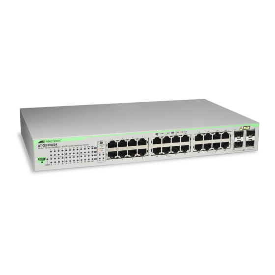
Allied Telesis AT-GS950/24 User Manual (366 pages)
Gigabit Ethernet Smart Switch Web Users Guide
Brand: Allied Telesis
|
Category: Network Router
|
Size: 10 MB
Table of Contents
Advertisement
Allied Telesis AT-GS950/24 Installation Manual (78 pages)
Gigabit Ethernet Smart Switches
Brand: Allied Telesis
|
Category: Network Router
|
Size: 2 MB
Table of Contents

Allied Telesis AT-GS950/24 Installation Manual (54 pages)
Allied Telesis - WebSmart 8-Port Gigabit Switch
Brand: Allied Telesis
|
Category: Network Router
|
Size: 1 MB
Table of Contents
Advertisement

Allied Telesis AT-GS950/24 Installation Manual (52 pages)
Gigabit Ethernet Smart Switch
Brand: Allied Telesis
|
Category: Network Router
|
Size: 0 MB
Table of Contents

Allied Telesis AT-GS950/24 Manual (30 pages)
Gigabit Ethernet Smart Switch How to Start a WEB Management Session
Brand: Allied Telesis
|
Category: Network Router
|
Size: 0 MB
Table of Contents

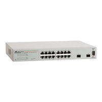
Allied Telesis AT-GS950/24 Datasheet (2 pages)
24 port Gigabit WebSmart Switch
Brand: Allied Telesis
|
Category: Switch
|
Size: 0 MB
Table of Contents
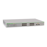
Allied Telesis AT-GS950/24 Datasheet (2 pages)
16 port Gigabit WebSmart Switch
Brand: Allied Telesis
|
Category: Switch
|
Size: 0 MB