Allied Telesis AT-GS950/16 Installation Manual
Gigabit ethernet smart switches
Hide thumbs
Also See for AT-GS950/16:
- User manual (404 pages) ,
- Installation manual (44 pages) ,
- Manual (44 pages)

Related Manuals for Allied Telesis AT-GS950/16


Summary of Contents for Allied Telesis AT-GS950/16
-
Page 1: Gigabit Ethernet
Gigabit Ethernet Smart Switches AT-GS950/16 AT-GS950/24 Installation Guide 613-000190 Rev. A... - Page 2 Copyright © 2005 Allied Telesyn, Inc. All rights reserved. No part of this publication may be reproduced without prior written permission from Allied Telesyn, Inc. Microsoft and Internet Explorer are registered trademarks of Microsoft Corporation. Netscape Navigator is a registered trademark of Netscape Communications Corporation.
-
Page 3: Electrical Safety And Emissions Standards
Electrical Safety and Emissions Standards This product meets the following standards. U.S. Federal Communications Commission Radiated Energy Note: This equipment has been tested and found to comply with the limits for a Class A digital device pursuant to Part 15 of FCC Rules. -
Page 4: Translated Safety Statements
Translated Safety Statements Important: Appendix B contains translated safety statements for installing this equipment. When you see the , go to Appendix B for the translated safety statement in your language. Wichtig: Anhang B enthält übersetzte Sicherheitshinweise für die Installation dieses Geräts. Wenn sehen, schlagen Sie in Anhang B den übersetzten Sicherheitshinweis in Ihrer Sprache nach. -
Page 5: Table Of Contents
Contents Preface ....................................9 Safety Symbols Used in this Document..........................10 Where to Find Web-based Guides ............................11 Contacting Allied Telesyn ..............................12 Online Support ................................12 Email and Telephone Support ............................12 Returning Products................................12 Sales or Corporate Information .............................12 Management Software Updates ............................12 Chapter 1: Overview ................................13 Features ....................................14 Front and Back Panels .................................15 Ports .....................................16... - Page 6 Contents Appendix B: Translated Safety Statements ........................51...
- Page 7 Figures Figure 1. AT-GS950/16 and AT-GS950/24 Front Panels ....................15 Figure 2. AT-GS950/16 and AT-GS950/24 Back Panels.....................15 Figure 3. AT-GS950/16 and GS950/24 System and Port LEDs ..................18 Figure 4. Power Workgroup Topology ..........................24 Figure 5. Collapsed Backbone - Hub Topology ........................25 Figure 6.
- Page 8 Figures...
- Page 9 Tables Table 1. Safety Symbols ..............................10 Table 2. System LEDs ................................18 Table 3. 10/100/1000Base-T Port LEDs ..........................18 Table 4. SFP Port LEDs ..............................19 Table 5. Twisted Pair Cabling and Distances ........................31 Table 6. MDI Pin Signals (10Base-T or 100Base-TX) ......................48 Table 7.
- Page 10 Tables...
-
Page 11: Preface
Preface This guide contains instructions on how to install the AT-GS950/16 and AT-GS950/24 Gigabit Ethernet Smart switches. This preface contains the following sections: “Safety Symbols Used in this Document” on page 10 “Where to Find Web-based Guides” on page 11... -
Page 12: Safety Symbols Used In This Document
Preface Safety Symbols Used in this Document This document uses the safety symbols defined in Table 1. Table 1. Safety Symbols Symbol Meaning Description Caution Performing or omitting a specific action may result in equipment damage or loss of data. Warning Performing or omitting a specific action may result in electrical shock. -
Page 13: Where To Find Web-Based Guides
Where to Find Web-based Guides The installation and user guides for all Allied Telesyn products are available in portable document format (PDF) on our web site at www.alliedtelesyn.com. You can view the documents online or download them onto a local workstation or server. -
Page 14: Contacting Allied Telesyn
To obtain an RMA number, contact Allied Telesyn Technical Support through our web site: www.alliedtelesyn.com. Sales or You can contact Allied Telesyn for sales or corporate information through our web site: www.alliedtelesyn.com. To find the contact information for Corporate your country, select Contact Us -> Worldwide Contacts. Information... -
Page 15: Chapter 1: Overview
Chapter 1 Overview The AT-GS950/16 and AT-GS950/24 Gigabit Ethernet Smart switches are Layer 2 Gigabit Ethernet switches designed to simplify the task of creating or expanding an Ethernet, Fast Ethernet, or Gigabit Ethernet network. This chapter contains the follows sections: “Features”... -
Page 16: Features
Chapter 1: Overview Features The features of the AT-GS950/16 and AT-GS950/24 Gigabit Ethernet Smart switches include: LEDs for unit and port status 16 or 24 Auto-Negotiating 10/100/1000Base-T twisted pair ports with RJ-45 connectors Two small form-factor pluggable (SFP) ports Auto MDI/MDI-X on the twisted pair ports IEEE 802.3 and IEEE 802.3u compliant... -
Page 17: Front And Back Panels
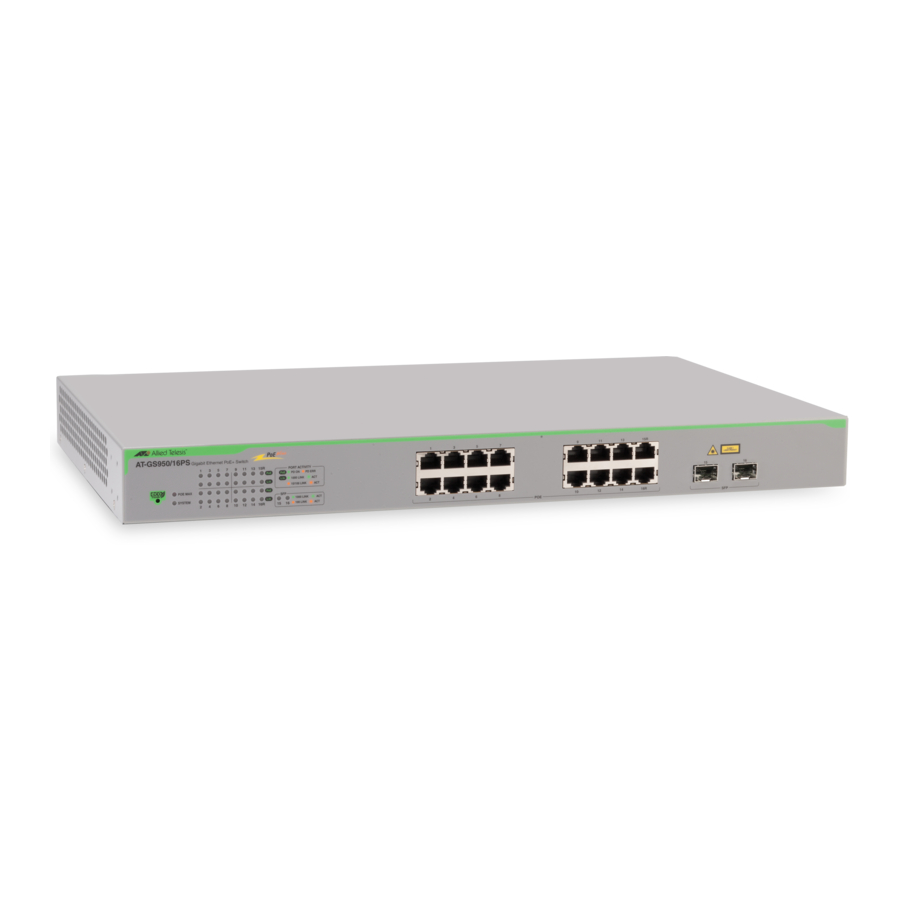
AT-GA950/16 and AT-GA950/24 Gigabit Ethernet Smart Switches Installation Guide Front and Back Panels Figure 1 illustrates the front panels of the AT-GS950/16 and AT-GS950/24 Gigabit Ethernet Smart switches. AT-GS950/16 AT-GS950/16 16-Port 10/100/1000Mbps + 2 SFP Combo WebSmart Switch SPEED LINK/ACT... -
Page 18: Ports
With Auto-Negotiation, the switch automatically matches the highest possible common speed between each switch port and each end node. For example, if an end node is capable of only 10 Mbps (AT-GS950/16), the switch sets the port connected to the end node to 10 Mbps. -
Page 19: Rs-232 Console Port
AT-GA950/16 and AT-GA950/24 Gigabit Ethernet Smart Switches Installation Guide the SFP ports (15 and 16 on the AT-GS950/16; 23 and 24 on the AT-GS950/24) and a fiber optic cable is connected, the corresponding twisted pair port is disabled. RS-232 Console The RS-232 console port uses the management cable supplied with the switch. -
Page 20: Leds
24-Port 10/100/1000Mbps + 2 SFP Combo WebSmart Switch SPEED LINK/ACT SPEED LINK/ACT LINK/ACT POWER Figure 3. AT-GS950/16 and GS950/24 System and Port LEDs Table 2 describes the AT-GS950/16 and AT-GS950/24 system LEDs. Table 2. System LEDs State Description POWER The switch is not receiving power. -
Page 21: Table 4. Sfp Port Leds
AT-GA950/16 and AT-GA950/24 Gigabit Ethernet Smart Switches Installation Guide Table 3. 10/100/1000Base-T Port LEDs (Continued) State Description Blinking The port is transmitting or receiving data. Green Green A valid link has been established on the port. Table 4 describes the LEDs for the SFP ports. Table 4. -
Page 22: Power Supply
Chapter 1: Overview Power Supply The switches have an internal power supply with a single AC power supply socket on the back panel which features autoswitch AC inputs. To power the switch on or off, connect or disconnect the power cord provided with the switch. -
Page 23: Ethernet Switching Basics
NIC already has a MAC address assigned to it by its manufacturer. The MAC address table in the AT-GS950/16 and AT-GS950/24 Gigabit Ethernet Smart switches can store up to 8K MAC addresses. The switch... -
Page 24: Duplex Mode
The twisted pair ports on the AT-GS950/16 and AT-GS950/24 Gigabit Ethernet Smart switches can operate in either half-or full-duplex mode. They are IEEE 802.3u-compliant and use Auto-Negotiation to set the duplex mode setting for you automatically. -
Page 25: Back Pressure And Flow Control
The switch continues to issue PAUSE frames until it is ready again to receive data from the end node. This is referred to as flow control. The AT-GS950/16 and AT-GS950/24 Gigabit Ethernet Smart switches support both TX and RX flow control. -
Page 26: Network Topologies
Chapter 1: Overview Network Topologies This section illustrates two network topologies that you can create with the AT-GS950/16 and AT-GS950/24 Gigabit Ethernet Smart switches: a power workgroup and collapsed backbone. Both types of topologies are described below. Power The topology shown in Figure 4 is commonly referred to as a power workgroup topology. -
Page 27: Collapsed Backbone
AT-GA950/16 and AT-GA950/24 Gigabit Ethernet Smart Switches Installation Guide Collapsed In the topology illustrated in Figure 5, an AT-GS950/16 connects Fast Ethernet switches that have Gigabit Ethernet uplinks. This type of topology Backbone is often referred to as a collapsed backbone topology. The switch functions... - Page 28 Chapter 1: Overview...
-
Page 29: Chapter 2: Installation
Chapter 2 Installation This chapter contains the following sections: “Reviewing Safety Precautions” on page 28 “Selecting a Site for the Switch” on page 30 “Cabling” on page 31 “Unpacking the Switch” on page 32 “Installing the Switch on a Desktop” on page 33 “Installing a Switch in a Rack”... -
Page 30: Reviewing Safety Precautions
Chapter 2: Installation Reviewing Safety Precautions Please review the following safety precautions before you begin to install the chassis or any of its components. Note When you see the , go to Appendix B, “Translated Safety Statements” on page 51 for translated safety statements. Warning: To prevent electric shock, do not remove the cover. - Page 31 AT-GA950/16 and AT-GA950/24 Gigabit Ethernet Smart Switches Installation Guide Circuit Overloading: Consideration should be given to the connection of the equipment to the supply circuit and the effect that overloading of circuits might have on overcurrent protection and supply wiring. Appropriate consideration of equipment nameplate ratings should be used when addressing this concern.
-
Page 32: Selecting A Site For The Switch
Chapter 2: Installation Selecting a Site for the Switch Observe the following requirements when choosing a site for your switch: If you plan to install the switch in an equipment rack, ensure that the rack is safely secured and that it will not tip over. Devices in a rack should be installed starting at the bottom, with the heavier devices near the bottom of the rack. -
Page 33: Cabling
Table 5 contains the cabling specifications for the twisted pair ports. Table 5. Twisted Pair Cabling and Distances Maximum Speed Type of Cable Operating Distance 10 Mbps (AT-GS950/16 Category 3 or better 100-ohm 100 m (328 ft) only) shielded or unshielded twisted pair cable 100 Mbps... -
Page 34: Unpacking The Switch
3. Ensure that the following hardware components are included in your switch package. If any item is missing or damaged, contact your Allied Telesyn sales representative for assistance. One AT-GS950/16 or AT-GS950/24 Smart Switch and the following: Two rack-mount brackets Eight rack-mount bracket screws (black) -
Page 35: Installing The Switch On A Desktop
AT-GA950/16 and AT-GA950/24 Gigabit Ethernet Smart Switches Installation Guide Installing the Switch on a Desktop You can place the AT-GS950/16 and AT-GS950/24 Gigabit Ethernet Smart switches on a desktop or install them in a 19-inch rack. To install the switch in a rack, refer to “Installing a Switch in a Rack” on page 34. -
Page 36: Installing A Switch In A Rack
Chapter 2: Installation Installing a Switch in a Rack To install the AT-GS950/16 or AT-GS950/24 switch in a rack, perform the following procedure: 1. If attached, remove the rubber feet using a flat-head screwdriver. 2. Install a bracket on one side of the switch using a Phillips screwdriver and four of the rack-mount screws included with the switch. -
Page 37: Figure 9. Mounting The At-Gs950/16 Switch On The Rack
AT-GA950/16 and AT-GA950/24 Gigabit Ethernet Smart Switches Installation Guide 4. Mount the switch on a 19-inch rack using the four large screws included. Figure 9 shows how to mount the AT-GS950/16 switch, and Figure 10 shows how to mount the AT-GS950/24 switch. - Page 38 Chapter 2: Installation Warning: Class I Equipment. This equipment must be earthed. The power plug must be connected to a properly wired earth ground socket outlet. An improperly wired socket outlet could place hazardous voltages on accessible metal parts. Pluggable Equipment. The socket outlet shall be installed near the equipment and shall be easily accessible.
-
Page 39: Installing An Optional Sfp Transceiver
AT-GA950/16 and AT-GA950/24 Gigabit Ethernet Smart Switches Installation Guide Installing an Optional SFP Transceiver The AT-GS950/16 and AT-GS950/24 Gigabit Ethernet Smart switches each have two SFP uplink ports. To install an SFP transceiver, perform the following procedure: Note The transceiver can be hot-swapped; you do not need to power off the switch to install a transceiver. -
Page 40: Figure 12. Inserting The Sfp
Chapter 2: Installation 4. Slide the SFP transceiver into an SFP slot on the switch, as shown in Figure 12. Figure 12. Inserting the SFP 5. Repeat steps 2 through 4 if you are installing another SFP transceiver. Note SFP transceivers are dust sensitive. When a fiber optic cable is not installed, or when you store the SFP, always keep the plug in the optical bores. -
Page 41: Cabling And Powering On The Switch
2. Connect the other end of the twisted pair cable to a port in the end node. Connecting the To connect a fiber optic cable to an SFP installed in the AT-GS950/16 and AT-GS950/24 Gigabit Ethernet Smart switches, perform the following Fiber Optic... -
Page 42: Powering On The Switch
Chapter 2: Installation 1. Remove the dust plug from the SFP, as shown in Figure 14. Figure 14. Removing the Dust Plug from the SFP 2. Connect the fiber optic cable to the SFP port, as shown in Figure 15. Figure 15. -
Page 43: Figure 16. Plugging In The Ac Power Cord
AT-GA950/16 and AT-GA950/24 Gigabit Ethernet Smart Switches Installation Guide Figure 16. Plugging in the AC Power Cord 2. Plug the other end of the power cord into a wall outlet. Warning: Power cord is used as a disconnection device. To de- energize equipment, disconnect the power cord. -
Page 44: Starting A Local Management Session
Chapter 2: Installation Starting a Local Management Session Starting a Local To start a local management session on an AT-GS950/16 or AT-GS950/ 24 Smart Switch, perform the following procedure: Management Session 1. Connect one end of the management cable to the console port on the switch, as shown in Figure 17. -
Page 45: Figure 18. Login Menu
AT-GA950/16 and AT-GA950/24 Gigabit Ethernet Smart Switches Installation Guide The Login Menu is shown in Figure 18. AT-GS950/16 Local Management System Enter the character in square brackets to select option Login Menu Login: Figure 18. Login Menu 4. Enter “manager” for the login name and press Return. - Page 46 Chapter 2: Installation...
-
Page 47: Chapter 3: Troubleshooting
Chapter 3 Troubleshooting This chapter contains information on how to troubleshoot the switch in the event that a problem occurs. Note If you need further assistance, please contact Allied Telesyn Technical Support. Refer to “Contacting Allied Telesyn” on page 12. Check the POWER LED on the front of the switch. - Page 48 Chapter 3: Troubleshooting...
-
Page 49: Appendix A: Technical Specifications
Storage Humidity: 5% to 95% non-condensing Operating Altitude Range: Up to 3,000 m (9,843 ft) Power Specifications Input Supply Voltage: 100 - 240 VAC Power Consumption: AT-GS950/16 33 W AT-GS950/24 37.2 W Safety and Electromagnetic Emissions Certifications EMI/RFI: FCC Class A, EN55022 Class A,... -
Page 50: Connectors And Port Pinouts
Connectors and Port Pinouts This section lists the connectors and connector pinouts for the AT-GS950/16 and AT-GS950/24 switches and their components. Figure 20 illustrates the pin layout for an RJ-45 connector and port. Figure 20. RJ-45 Connector and Port Pin Layout Table 6 lists the RJ-45 pin signals when a twisted pair port is operating in the MDI configuration. -
Page 51: Table 8. Rj-45 1000Base-T Connector Pinouts
AT-GA950/16 and AT-GA950/24 Gigabit Ethernet Smart Switches Installation Guide 1000Base-T port is operating at 1000 Mbps. Table 8. RJ-45 1000Base-T Connector Pinouts Pair Signal TX and RX+ TX and RX- TX and RX+ TX and RX+ TX and RX- TX and RX- TX and RX+ TX and RX-... - Page 52 Appendix A: Technical Specifications...
- Page 53 Appendix B Translated Safety Statements Important: This appendix contains multiple-language translations for the safety statements in this guide. Wichtig: Dieser Anhang enthält Übersetzungen der in diesem Handbuch enthaltenen Sicherheitshinweise in mehreren Sprachen. Importante: Este apéndice contiene traducciones en múltiples idiomas de los mensajes de seguridad incluidos en esta guía.
-
Page 54: Laser Safety Notices
Appendix B: Translated Safety Statements Laser Safety Notices Warning: Class 1 Laser product. Warning: Do not stare into the laser beam. Electrical Safety Notices Warning: To prevent electric shock, do not remove the cover. No user-serviceable parts inside. This unit contains hazardous voltages and should only be opened by a trained and qualified technician. - Page 55 AT-GA950/16 and AT-GA950/24 Gigabit Ethernet Smart Switches Installation Guide Warning: Check to see if there are any exposed copper strands coming from the installed wire. When this installation is done correctly there should be no exposed copper wire strands extending from the terminal block. Any exposed wiring can conduct harmful levels of electricity to persons touching the wires.
- Page 56 Appendix B: Translated Safety Statements Warning: Mounting of the equipment in the rack should be such that a hazardous condition is not created due to uneven mechanical loading. Warning: Remove all metal jewelry, such as rings and watches, before installing or removing a line card from a powered-on chassis.
-
Page 57: Telecommunications Compliance Notices
AT-GA950/16 and AT-GA950/24 Gigabit Ethernet Smart Switches Installation Guide Telecommunications Compliance Notices Warning: When using your telephone equipment, basic safety precautions should always be followed to reduce the risk of fire, electronic shock, and injury to persons, including the following: Do not use this product near water, for example, near a bathtub, washbowl, kitchen sink, or laundry tub in a wet basement or near a swimming pool. - Page 58 Appendix B: Translated Safety Statements Lasersicherheitshinweise Achtung: Laserprodukt der Klasse 1. Achtung: Blicken Sie nicht in den Laserstrahl. Elektrische Sicherheitshinweise Achtung: Um Stromschläge zu vermeiden, darf die Abdeckung nicht entfernt werden. Die Ausrüstung enthält keine benutzerwartbaren Teile. Diese Einheit führt gefährliche Spannungen und sollte nur durch einen ausgebildeten und qualifizierten Techniker geöffnet werden.
- Page 59 AT-GA950/16 and AT-GA950/24 Gigabit Ethernet Smart Switches Installation Guide Achtung: Nicht mehr als die empfohlene Kabellänge abisolieren. Durch das Abisolieren von mehr als der empfohlenen Länge können gefährliche blanke Drähte aus dem Anschlussblock hervorragen. Achtung: Beim Installieren dieser Ausrüstung ist stets darauf zu achten, dass die Rahmenerdung zuerst angeschlossen und zuletzt abgetrennt wird.
- Page 60 Appendix B: Translated Safety Statements Bei der Versorgung der Einheit durch zentralisierten Gleichstrom ist ein Tray-Kabel zum Anschluss der Stromquelle erforderlich. Das Tray-Kabel muss ein UL-gelistetes Typ-TC-Tray-Kabel mit einer Nennspannung von 600 V und einer Nenntemperatur von 90 Grad Celsius, mit drei Leitern und mindestens 14 AWG sein. Achtung: Bei der Rackmontage der Ausrüstung ist darauf zu achten, dass keine Gefahrenbedingung durch ungleichmäßige mechanische Belastung geschaffen wird.
- Page 61 AT-GA950/16 and AT-GA950/24 Gigabit Ethernet Smart Switches Installation Guide Telekommunikationskonformitätshinweise Achtung: Bei der Verwendung Ihrer Telefonausrüstung sollten zur Reduzierung der Brand-, Stromschlag und Verletzungsgefahr stets grundsätzliche Sicherheitsrichtlinien, einschließlich der folgenden, befolgt werden: Verwenden Sie dieses Produkt nicht in der Nähe von Wasser, zum Beispiel in der Nähe einer Badewanne, einer Waschschüssel, eines Spülbeckens, eines Waschbottichs, in einem nassen Kellerraum oder in der Nähe eines Schwimmbads.
- Page 62 Appendix B: Translated Safety Statements Avisos de seguridad láser Atención: Producto láser de clase 1. Atención: No mire el rayo láser. Avisos de seguridad eléctricas Atención: Para evitar la electrocución, no quite la tapa. La unidad no contiene piezas que pueda reparar el usuario. Esta unidad contiene tensiones peligrosas y sólo la debe abrir un técnico convenientemente formado y cualificado.
- Page 63 AT-GA950/16 and AT-GA950/24 Gigabit Ethernet Smart Switches Installation Guide Atención: Cuando instale el equipo, asegúrese de instalar primero la conexión a tierra del bastidor y de desconectarla en último lugar. Atención: Compruebe si hay algún hilo de cobre al descubierto que proceda del cable instalado.
- Page 64 Appendix B: Translated Safety Statements Atención: Si el equipo se monta en un rack, se deberá evitar todo peligro de irregularidad en la carga mecánica. Atención: Quítese todas las joyas metálicas, como anillos y relojes, antes de instalar o quitar una tarjeta de red de un chasis con alimentación eléctrica. Utilice circuitos de alimentación dedicados o acondicionadores de alimentación para suministrar energía eléctrica fiable al dispositivo.
- Page 65 AT-GA950/16 and AT-GA950/24 Gigabit Ethernet Smart Switches Installation Guide Avisos de conformidad de telecomunicaciones Atención: Cuando utilice su equipo telefónico, deberá adoptar las siguientes precauciones de seguridad básicas para reducir el riesgo de incendio, descarga electrónica y lesiones: No utilice este producto en zonas húmedas; por ejemplo, cerca de una bañera, un lavabo o un fregadero, en un sótano húmedo o cerca de una piscina.
- Page 66 Appendix B: Translated Safety Statements Avis de sécurité laser Avertissement: Produit laser de classe 1. Avertissement: Ne pas observer directement le rayon laser. Avis de sécurité électrique Avertissement: Pour éviter tout risque d’électrocution, ne pas déposer le capot. L’appareil ne contient aucun composant réparable par l’utilisateur. Il est exposé à des tensions dangereuses et ne doit être ouvert que par un technicien compétent et qualifié.
- Page 67 AT-GA950/16 and AT-GA950/24 Gigabit Ethernet Smart Switches Installation Guide Avertissement: Respecter les recommandations pour dénuder les fils. Un dénudage excessif risque de présenter des risques pour la sécurité en laissant le fil exposé sur le bornier après l’installation. Avertissement: Lors de l’installation de cet équipement, toujours s’assurer que la connexion de terre de la structure est installée en premier et déconnectée en dernier.
- Page 68 Appendix B: Translated Safety Statements Un chemin de câble doit être utilisé pour la connexion à la source d’alimentation si l’unité est alimentée par alimentation c.c. centralisée. Le chemin de câble doit être de type TC agréé UL, intensité nominale de 600 V, 90 °C, trois conducteurs, 14 AWG minimum.
- Page 69 AT-GA950/16 and AT-GA950/24 Gigabit Ethernet Smart Switches Installation Guide Télécommunications – Avis de conformité Avertissement: Les précautions élémentaires de sécurité doivent être systématiquement respectées en utilisant l’équipement téléphonique pour réduire les risques d’incendie, d’électrocution et d’accident corporel, notamment: Ne pas utiliser ce produit près d’une source d’eau, telle qu’une baignoire, un lavabo, un évier ou un baquet dans un sous-sol humide ou près d’une piscine.
- Page 70 Appendix B: Translated Safety Statements Indicazioni sulla sicurezza laser Avvertenza: Prodotto laser Classe 1. Avvertenza: Non fissare il raggio laser. Indicazioni sulla sicurezza elettrica Avvertenza: Per evitare scosse elettriche, non rimuovere la copertura. All'interno non sono presenti componenti utilizzabili dall'utente. Questa unità presenta voltaggi rischiosi e deve essere aperta solo da un tecnico qualificato ed esperto.
- Page 71 AT-GA950/16 and AT-GA950/24 Gigabit Ethernet Smart Switches Installation Guide Avvertenza: Quando si installa l'apparecchiatura, verificare che il collegamento di messa a terra FG (frame ground) sia installato per primo e disinstallato per ultimo. Avvertenza: Verificare che non sporgano fili di rame dai cavi installati. Se l'installazione viene effettuata correttamente, non vi sono fili di rame scoperti, sporgenti dal blocco terminale.
- Page 72 Appendix B: Translated Safety Statements Avvertenza: Rimuovere tutti gli oggetti di metallo, ad esempio anelli e orologi, prima di installare o estrarre una scheda di linea da un chassis acceso. Utilizzare circuiti di alimentazione o alimentatori dedicati per fornire energia elettrica al dispositivo in modo affidabile.
- Page 73 AT-GA950/16 and AT-GA950/24 Gigabit Ethernet Smart Switches Installation Guide Indicazioni per la conformità con le norme sulle telecomunicazioni Avvertenza: Quando si utilizza l'apparecchiatura telefonica, per ridurre il rischio di incendio, scosse elettriche e danni alle persone, è necessario seguire alcune precauzioni di base per la sicurezza, ad esempio: Non utilizzare il prodotto in prossimità...
- Page 74 Appendix B: Translated Safety Statements Лазерная безопасность Внимание: лазерный продукт, класс 1. Внимание: Не смотрите прямо в лазерный луч. Электрическая безопасность Внимание: Для предотвращения электрического шока, не снимайте кожух. Внутри нет частей, подлежащих обслуживанию пользователем. Этот устройство – под опасным напряжением и должно открываться только обученным и квалифицированным...
- Page 75 AT-GA950/16 and AT-GA950/24 Gigabit Ethernet Smart Switches Installation Guide Внимание: При инсталляции оборудования, убедитесь, что заземление подключается в первую, а отключается в последнюю очередь. Внимание: Проверьте, нет ли на инсталлированных проводков на кабеле. При правильной инсталляции на терминале свободных проводков быть не должно. Открытые...
- Page 76 Appendix B: Translated Safety Statements Для подсоединения источника питания, если установка питается централизованным постоянным током, требуется желобной кабель. Кабель должен быть признанным UL типа и предназначен для 600 В и + 90°C, с тремя кондукторами, минимум 14 AWG (американский калибр). Внимание: Установка...
- Page 77 AT-GA950/16 and AT-GA950/24 Gigabit Ethernet Smart Switches Installation Guide Телекоммуникационное соответствие Внимание: При использовании телефонного оборудования, всегда следует обращать внимания на требования безопасности для снижения риска пожара, поражения током и ранения, в том числе: Не используйте оборудование рядом с водой – например ванной, раковиной или стиральным...
- Page 78 Appendix B: Translated Safety Statements...
Need help?
Do you have a question about the AT-GS950/16 and is the answer not in the manual?
Questions and answers