Sign In
Upload
Manuals
Brands
Allied Telesis Manuals
Switch
AT-GS950/16PS
Allied Telesis AT-GS950/16PS Manuals
Manuals and User Guides for Allied Telesis AT-GS950/16PS. We have
6
Allied Telesis AT-GS950/16PS manuals available for free PDF download: User Manual, Installation Manual, Product Information
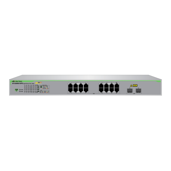
Allied Telesis AT-GS950/16PS User Manual (386 pages)
Gigabit Ethernet PoE+ Switch
Brand:
Allied Telesis
| Category:
Switch
| Size: 12.66 MB
Table of Contents
Table of Contents
3
List of Figures
9
List of Tables
13
Preface
15
Document Conventions
16
Allied Telesis Contact Information
17
Getting Started
19
Chapter 1 : Starting a Web Browser Session
21
Establishing a Remote Connection to the Web Browser Interface
22
Figure 1. Entering a Switch's IP Address in the URL Field
22
Figure 2. Management Login Dialog Box
22
Figure 3. AT-GS950/16PS Switch Information Page
23
Figure 4. Front Panel Page
24
Web Browser Tools
25
Quitting a Web Browser Management Session
26
Chapter 2 : System Configuration
27
System Management Information
28
Figure 5. AT-GS950/16PS Management Page
28
Configuration of IP Address, Subnet Mask and Gateway Address
30
Figure 6. IP Setup Page
30
IP Access List Configuration
32
Create an IP Access List
32
Figure 7. IP Access List Page
32
Delete an IP Address List Entry
33
User Name and Password Configuration
34
Add New User Name and Password
34
Figure 8. Administration Page
34
Modify User Name and Password
35
Figure 9. Modify Administration Page
35
Delete User Name and Password
36
User Interface Configuration
37
SNMP Interface
37
Figure 10. User Interface Page
37
User Interface Timeout
38
System Time
39
Manually Setting System Time
39
Figure 11. System Time Page
39
Setting SNTP
40
Setting Daylight Savings Parameters
41
SSL Settings
42
Configuring SSL
42
Figure 12. SSL Settings Page
42
DHCP and ATI Web Discovery Tool
44
DHCP Client Configuration
45
DHCP Auto Configuration
47
Figure 13. DHCP Auto Configuration Settings Page
47
System Information Display
48
Figure 14. AT-GS950/16PS Switch Information Page
48
System Log Configuration
50
Figure 15. System Log Configuration Page
50
Bridge Configuration
53
Chapter 3 : Port Configuration
55
Overview
56
Displaying and Configuring Ports
57
Figure 16. AT-GS950/16PS Physical Interface Page
57
Chapter 4 : STP and RSTP
61
Overview
62
Bridge Priority and the Root Bridge
63
Table 1 Bridge Priority Value Increments
63
Port Priority
64
Forwarding Delay and Topology Changes
65
Table 2. Valid Port Priority Values
65
Mixed STP and RSTP Networks
67
Figure 17. Point-To-Point Ports
67
Figure 18. Edge Port
67
Spanning Tree and Vlans
68
Figure 19. STP and VLAN Fragmentation with Untagged Ports
68
Figure 20. STP and VLAN Compatibility with Tagged Ports
69
Basic STP and RSTP Configuration
70
Figure 21. Rapid Spanning Tree Configuration Page
70
Configure RSTP Port Settings
73
Configure the Basic RSTP Port Settings
73
Figure 22. AT-GS950/16PS RSTP Basic Port Configuration Page
73
Configure the Advanced RSTP Port Settings
75
Figure 23. AT-GS950/16PS RSTP Advanced Port Configuration Page
75
Spanning Tree Topology
78
Figure 24. AT-GS950/16PS Designated Topology Information Page
78
Chapter 5 : Multiple Spanning Tree Protocol
79
Multiple Spanning Tree Configuration
80
Figure 25. Multiple Spanning Tree Configuration Page
80
Port Configuration
83
Figure 26. AT-GS950/16PS MSTP Port Configuration Page
83
VLAN Mapping
86
Open MSTP VLAN Mapping Page
86
Create VLAN Mapping to MST Instance
86
Figure 27. MSTP VLAN Mapping Page
86
Modify MST Instance
87
Delete MST Instance
87
Port Settings
88
Figure 28. MSTP Port Settings Page
88
Topology Information
90
Figure 29. AT-GS950/16PS Topology Information Page
90
Chapter 6 : Static Port Trunking
93
Overview
94
Figure 30. Static Port Trunk Example
94
Create a Port Trunk
97
Figure 31. Trunking Page
97
Modify a Port Trunk
99
Disable a Port Trunk
101
Chapter 7 : LACP Port Trunks
103
Overview
104
System Priority
105
Port Priority Value
106
General Guidelines
107
Group Status
109
Figure 32. LACP Group Status Page
109
Configuration Example
110
Figure 33. LACP Group Status Page with no Cables Connected
110
Figure 34. LACP Group Status Page with Three Cables Connected
111
Port Priority Configuration
112
Figure 35. AT-GS950/16PS Port Priority Page
112
Chapter 8 : Port Mirroring
113
Overview
114
Port Mirroring Configuration
115
Figure 36. AT-GS950/16PS Mirroring Page
115
Disable Port Mirroring
117
Chapter 9 : Loopback Protection
119
Configuration
120
Figure 37. AT-GS950/16PS Loopback Detection Page
120
Status
122
Chapter 10 : MAC Address Table
123
Overview
124
Static Unicast MAC Address Configuration
126
Figure 38. AT-GS950/16PS Static Unicast Address Table Page
126
Figure 39. Static Unicast Address Table with Port-Base VLAN Example
127
Modify Static Unicast Address
128
Figure 40. Modify Static Unicast Address Page
128
Delete Static Unicast Address
129
Static Multicast Address Configuration
130
Figure 41. AT-GS950/16PS Static Multicast Address Table Page
130
Figure 42. Static Multicast Address Table Example
131
Modify Static Multicast Address
133
Figure 43. Modify Static Multicast Address Page
133
Delete Static Multicast Address
134
Chapter 11 : IGMP Snooping
135
Overview
136
IGMP Snooping Configuration
138
Figure 44. IGMP Snooping Page
138
Figure 45. IGMP Snooping Page with MAC Addresses
139
Chapter 12 : Storm Control
141
Overview
142
Ingress Rate Limiting
143
Egress Rate Limiting
143
Configuration
144
Figure 46. AT-GS950/16PS Storm Control Page
144
Ingress Rate Limiting
146
Figure 47. AT-GS950/16PS Ingress Rate Limiting Page
146
Egress Rate Limiting
148
Figure 48. AT-GS950/16PS Egress Rate Limiting Page
148
Chapter 13 : Virtual Lans
149
VLAN Overview
150
Port-Based VLAN Overview
151
Tagged VLAN Overview
152
General Rules for Creating a Tagged VLAN
154
Assign Ports to a VLAN Mode
155
Figure 49. AT-GS950/16PS VLAN Mode Page
155
Tagged VLAN Configuration
157
Create a Tagged VLAN
157
Figure 50. AT-GS950/16PS Tagged VLAN Page
157
Modify a Tagged VLAN
158
Figure 51. Example of AT-GS950/16PS Tagged VLAN Page
159
Figure 52. AT-GS950/16PS Modify VLAN Page
159
Delete a Tagged VLAN
160
Tagged VLAN Port Settings
162
Figure 53. AT-GS950/16PS VLAN Port Setting Page
162
Port-Based VLAN Configuration
164
Create a Port-Based VLAN
164
Figure 54. Port-Based VLAN Page
164
Modify a Port-Based VLAN
165
Figure 55. Example of AT-GS950/16PS Port Based VLAN Page
165
Chapter 14 : GVRP
167
Overview and Guidelines
168
General Configuration
169
Figure 56. GVRP Global Configuration Page
169
Port Settings
170
Figure 57. GVRP Port Setting Page
170
Time Settings
172
Figure 58. AT-GS950/16PS GVRP Time Setting Page
172
Chapter 15 : Quality of Service and Cost of Service
175
Chapter 15 Overview
176
Packet Priority
176
Egress Queue Vs Packet Priority Mapping
177
Table 3. Default Mappings Priority Levels to Priority Queues
177
Table 4. Customized Mappings Priority Levels to Priority Queues
177
Prioritizing Untagged Packets
178
Scheduling
178
Table 5. Example of Weighted Round Robin Priority
179
Mapping Cos Priorities to Egress Queues
180
Figure 59. Cos Page
180
Associate Ports to Cos Priorities
182
Figure 60. AT-GS950/16PS Port Priority Page
182
Associate DSCP Classes to Egress Queues
183
Figure 61. DSCP Class Mapping Page
183
Queue Scheduling Algorithm
185
Figure 62. Scheduling Algorithm Page
185
Advanced Features
187
Chapter 16 : Snmpv1 and V2C
189
Snmpv1 and Snmpv2C Overview
190
Trap Receiver Attributes
191
Activate SNMP Interface
192
Snmpv1 and Snmpv2C User and Group Names
193
Create User and Group Names
193
Figure 63. SNMP User/Group Page
193
Modify User and Group Names
194
Figure 64. SNMP User/Group Page Example
194
Delete User and Group Names
195
SNMP Community Strings
196
Create SNMP Community Strings
196
Figure 65. Community Table Page
196
Modify SNMP Community Strings
197
Delete SNMP Community Strings
197
Figure 66. SNMP Community Table Page Example
197
SNMP Traps
198
Create Trap Host Table Entry
198
Figure 67. Trap Management Page
198
Modify a Trap Host Table Entry
199
Delete a Trap Host Table Entry
199
Figure 68. Trap Management Page Example
199
Chapter 17 : Snmpv3
201
Overview
202
Snmpv3 Authentication Protocols
202
Snmpv3 Privacy Protocol
203
Snmpv3 MIB Views
203
Figure 69. MIB Tree
203
Snmpv3 Configuration Process
204
Figure 70. Snmpv3 Table Relationships
205
Snmpv3 User and Group Names
206
Creating Snmpv3 User and Group Names
206
Modifying Snmpv3 User and Group Names
207
Deleting Snmpv3 User and Group Names
207
Figure 71. SNMP User Group, Snmpv3 Example
207
Snmpv3 View Names
209
Creating Snmpv3 View Names
209
Figure 72. SNMP Group Access Table
209
Figure 73. SNMP Group Access Table Example for Snmpv3
210
Modifying Snmpv3 View Names
211
Deleting Snmpv3 View Names
211
Snmpv3 View Table
212
Creating Snmpv3 View Table Entries
212
Figure 74. SNMP View Table
212
Modifying Snmpv3 View Table Entries
213
Deleting Snmpv3 View Table Entries
213
Figure 75. SNMP View Table Page Example
213
Snmpv3 Traps
215
Chapter 18 : Access Control Configuration
217
Overview
218
Classifier
219
Creating a Classifier
219
Figure 76. Create Classifier Page
219
Modifying a Classifier
221
Figure 77. Create Classifier Example Page
221
Deleting a Classifier
222
Figure 78. Modify Classifier Page
222
Profile Action
224
Creating a Profile Action
224
Figure 79. Create Profile Action Page
224
Modifying Profile Action
225
Figure 80. Example of Profile Action Entry
225
Deleting a Profile Action
226
Figure 81. Modify Profile Action Page
226
In-Profile Action
227
Creating an In-Profile Action
227
Figure 82. Create In-Profile Action Page Example
227
Figure 83. Example of In-Profile Action Entry
228
Modifying an In-Profile Action
229
Figure 84. Modify In-Profile Action Page
229
Deleting an In-Profile Action
230
Out-Profile Action
231
Creating a Out-Profile Action
231
Figure 85. Create Out-Profile Action Page
231
Figure 86. Example of Out-Profile Action Entry
232
Modify Out-Profile Action
233
Figure 87. Modify Out-Profile Action Page
233
Delete Out-Profile Action
234
Port List
235
Create Port List
235
Figure 88. Create Port List Page
235
Modify Port List
236
Figure 89. Example of Port List Entry
236
Figure 90. Modify Port List Page
236
Delete Port List
237
Policy
238
Create Policy
238
Figure 91. Create Policy Page
238
Modify Policy
240
Figure 92. Example of Policy Entry
240
Delete Policy
241
Figure 93. Modify Policy Page
241
Policy Sequence Status
243
Figure 94. Policy Sequence Page
243
Figure 95. Policy Sequence Page with Display by Index Selected
243
Chapter 19 : RMON
245
Overview
246
Enable and Disable RMON
247
Figure 96. RMON Basic Settings Page
247
Port Statistics
248
Figure 97. Ethernet Statistics Configuration Page
248
Figure 98. Ethernet Statistics Configuration Example
249
Histories
250
Figure 99. History Control Configuration Page
250
Figure 100. History Control Configuration Example Page
251
Events
252
Figure 101. RMON Event Configuration Page
252
Figure 102. RMON Event Configuration Example Page
253
Alarms
254
Figure 103. RMON Alarm Configuration Page
255
Figure 104. RMON Alarm Configuration Example Page (to be Provided)
256
Chapter 20 : Voice VLAN
257
Overview
258
Cos with Voice VLAN
258
Organization Unique Identifier (OUI)
258
Dynamic Auto-Detection Vs Static Ports
259
General Guidelines
261
Configuration
262
Figure 105. AT-GS950/16PS Voice VLAN Setting Page
262
OUI Setting
265
Create OUI Setting
265
Figure 106. Voice VLAN OUI Setting Page
265
Modify OUI Setting
266
Delete OUI Setting
266
Chapter 21 : Security
267
Figure 113. Destination MAC Filter
267
Port Access Control
268
Overview
268
Port Access Control Configuration
269
Figure 107. Port Access Control Configuration Page
269
Figure 108. Expanded Port Access Control Configuration Page
270
RADIUS Client
273
Overview
273
General Guidelines
273
Radius Client Configuration
274
Figure 109. RADIUS Page
274
Dial-In User- Local Authentication
276
Overview
276
Dial-In User Configuration
276
Figure 110. Dial-In User Page
277
Figure 111. Dial-In User Page Example
277
Destination MAC Filter
279
Overview
279
Destination MAC Filter Configuration
279
Delete Destination MAC Filter
280
Figure 112. Destination MAC Filter Page
280
Chapter 22 : Power over Ethernet (Poe)
283
Overview
284
Power Sourcing Equipment (PSE)
284
Powered Device (PD)
284
PD Classes
284
Power Budget
284
Table 6. IEEE Powered Device Classes
284
Port Prioritization
285
Table 7. Poe Port Priorities
285
Poe Configuration
286
Figure 114. Power over Ethernet Configuration Page
286
Chapter 23: DHCP Snooping
290
Overview
291
Trusted Ports
291
Untrusted Ports
291
Unauthorized DHCP Servers
291
DHCP with Option 82
292
General Guidelines
293
General Configuration
294
Figure 115. General Settings Page
294
VLAN Setting
296
Creating a VLAN
296
Figure 116. DHCP Snooping VLAN Settings Page
296
Modifying a VLAN
297
Deleting a VLAN
297
Trusted and Untrusted Port Configuration
298
Figure 117. AT-GS950/16PS Trusted Interfaces Page
298
Figure 118. Trusted Interfaces Page Example
299
Binding Database
300
Static IP Addresses
300
Figure 119. AT-GS950/16PS Binding Database Page
300
Viewing
301
Figure 120. Binding Database Page Example
301
Chapter 24 : LLDP
303
Overview
304
Global Configuration
305
Figure 121. AT-GS950/16PS LLDP Global Settings Page
305
Enabling or Disabling LLDP
306
Displaying System Information
307
Setting Port States
307
Neighbors Information
309
Figure 122. LLDP Neighbors Information Page
309
Chapter 25 : Network Statistics
311
Overview
312
Traffic Comparison Statistics
313
Figure 123. Traffic Comparison Page
313
Table 8 Traffic Comparison Options
314
Error Group Statistics
316
Figure 124. Error Group Chart Page
316
Historical Status Charts
318
Figure 125. Historical Status Chart Page
318
Table 9 Historical Status Options
319
Tools
321
Chapter 26 : Software/Configuration Updates
323
Overview
324
Upgrade Firmware Image Via HTTP
325
Figure 126. Firmware Upgrade Via HTTP Page
326
Upgrade Firmware Image Via TFTP
327
Figure 127. Firmware Upgrade Via TFTP Page
328
Upload or Download a Configuration File Via HTTP
329
Configuration File Upload
329
Figure 128. Configuration File Upload/Download Via HTTP Page
329
Figure 129. Result Page
330
Configuration File Download
331
Figure 130. File Download with HTTP
331
Download or Upload a Configuration File Via TFTP
332
Configuration File Upload
332
Figure 131. Configuration Upload/Download Via TFTP Page
332
Configuration File Download
333
Chapter 27 : Cable Diagnostics
335
Figure 132. Cable Diagnostics Page
335
Chapter 28 : Rebooting the AT-GS950/16PS
337
Switch Reboot
338
Figure 133. Factory Default Reset/Reboot Page
338
Configure Factory Default Values
340
Password Protection of Factory Reset
342
Disabling Factory Default Reset Feature
342
Figure 134. Factory Default Reset/Reboot Page with Password Entry
343
Enabling Factory Default Reset
344
Figure 135. Factory Default Reset Disabled Page
344
Figure 136. Factory Default Reset/Reboot Page with Password Entry
345
Chapter 29 : Pinging a Remote System
347
Figure 137. Ping Test Configuration Page
347
Figure 138. Ping Test Results Page
348
Appendix A: MSTP Overview
349
Overview
350
Multiple Spanning Tree Instance (MSTI)
352
Resolving VLAN Fragmentation
352
Figure 139. VLAN Fragmentation with STP or RSTP
352
Multiple Vlans Assigned to an MSTI
353
Figure 140. MSTP Example of Two Spanning Tree Instances
353
Figure 141. Multiple Vlans in a MSTI
354
General Guidelines
355
VLAN and MSTI Associations
356
Ports in Multiple Mstis
357
Multiple Spanning Tree Regions
358
Table 10. MSTP Region
359
MST Region Guidelines
360
Table 11. Regional Bridge Priority Value Increments
360
Common and Internal Spanning Tree (CIST)
362
MSTP with STP and RSTP
362
Associating Vlans to Mstis
363
Figure 142. CIST and VLAN Guideline - Example 1
363
Figure 143. CIST and VLAN Guideline - Example 2
364
Vlans Across Different Regions
365
Figure 144. Spanning Regions - Example 1
365
Figure 145. Spanning Regions Without Blocking
366
Summary of Guidelines
367
Appendix B: AT-GS950/16PS Default Parameters
369
Table 12. AT-S112 Management Software Default Settings
369
Specifications
370
Default Setting
373
Statistics Chart
384
Advertisement
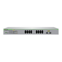
Allied Telesis AT-GS950/16PS Installation Manual (72 pages)
Gigabit Ethernet PoE+ Switches
Brand:
Allied Telesis
| Category:
Switch
| Size: 0.63 MB
Table of Contents
Table of Contents
5
Preface
11
Symbol Conventions
12
Contacting Allied Telesis
13
Chapter 1 : Overview
15
Features
16
Front and Back Panels
18
Figure 1: AT-GS950/10PS and AT-GS950/16PS Front Panels
18
Figure 2: AT-GS950/28PS and AT-GS950/48PS Front Panels
19
Figure 3: AT-GS950/10PS Back Panel
20
Figure 4: AT-GS950/16PS and AT-GS950/28PS Back Panels
20
Figure 5: AT-GS950/48PS Back Panel
20
Management Software
21
Twisted Pair Ports
22
Power over Ethernet (Poe)
23
Combo Ports
24
Table 1. Combo Ports
24
Leds
26
Figure 6: PWR LED on AT-GS950/10PS
26
Table 2. AT-GS950/10PS PWR LED Functional Descriptions
26
Figure 7: SYSTEM LED on AT-GS950/16PS
27
Figure 8: SYS LED on AT-GS950/28PS
27
Figure 9: SYS LED on AT-GS950/48PS
27
Figure 10: AT-GS950/10PS Link/Activity and Speed Leds
28
Table 3. AT-GS950/16PS, AT-GS950/28PS, and AT-GS950/48PS SYS LED Functional Descriptions
28
Figure 11: AT-GS950/16PS Link/Activity/Speed Leds
29
Figure 12: AT-GS950/28PS Link/Activity/Speed Leds
29
Table 4. AT-GS950/10PS L/A and SPD Leds Functional Descriptions
29
Figure 13: AT-GS950/48PS Link/Activity/Speed Port Leds
30
Table 5. AT-GS950/16PS, AT-GS950/28PS, and AT-GS950/48PS L/ALED Functional Descriptions
30
Figure 14: AT-GS950/10PS SFP Status Leds
31
Figure 15: AT-GS950/16PS SFP Status Leds
31
Figure 16: AT-GS950/28PS SFP Status Leds
31
Figure 17: AT-GS950/48PS SFP Status Leds
32
Table 6. SFP Slot LED Functional Descriptions - AT-GS950/10PS, AT-GS950/16PS, AT-GS950/48PS
32
Table 7. SFP Slot LED Functional Descriptions - AT-GS950/28PS
33
Figure 18: AT-GS950/10PS Poe and Poe MAX Leds
34
Figure 19: AT-GS950/16PS Poe and Poe MAX Leds
34
Figure 20: AT-GS950/28PS Poe and Poe MAX Leds
34
Figure 21: AT-GS950/48PS Poe and Poe MAX Leds
34
Table 8. Poe Status LED Functional Descriptions
35
Eco-Friendly Button
36
Figure 22: Eco-Friendly Button
36
Power Supply
38
Fans
39
Chapter 2 : Installation
41
Reviewing Safety Precautions
42
Figure 23: AT-GS950/28PS Unit Orientation
45
Selecting a Site for the Switch
46
Cable Specifications
47
Table 9. Twisted Pair Cabling and Distances
47
Unpacking the Switch
48
Figure 24: Shipping Package Contents
49
Installing the Switch on a Desktop
50
Figure 25: Attaching the Rubber Feet
50
Installing the Switch in an Equipment Rack
51
Figure 26: Attaching the Rack-Mount Brackets to the Switch
51
Figure 27: Attaching the Rack-Mount Brackets to the Switch (Continued)
52
Figure 28: Mounting the Switch in an Equipment Rack
52
Installing the Switch on a Wall
53
Figure 29: Attaching the Brackets to Install the Switch on a Wall
53
Figure 30: Marking the Screw Hole Locations
54
Figure 31: Securing the Switch to the Wall
55
Installing Optional SFP Transceivers
56
Figure 32: Inserting the SFP
57
Figure 33: Positioning the SFP Handle in the Upright Position
57
Cabling the Switch
59
Powering on the Switch
60
Figure 34: Installing the Retaining Clip
60
Figure 35: Raising the Retaining Clip
61
Figure 36: Plugging in the AC Power Cord
61
Figure 37: Lowering the Retaining Clip
62
Figure 38: Plugging in the AC Power Cord
63
Managing the Switch
64
Chapter 3 : Troubleshooting
65
Appendix A: Technical Specifications
69
Physical Specifications
69
Table 10. Chassis Dimensions
69
Table 11. Chassis Weight
69
Environmental Specifications
70
Power Specifications
70
Poe Specifications
70
Table 12. Environmental Specifications
70
Table 13. Max AC Input Power Specifications
70
Safety and Electromagnetic Emissions Certifications
71
Connectors and Port Pinouts
71
Figure 39: RJ-45 Connector and Port Pin Layout
71
Table 14. Max Ports Supported Per Poe Class
71
Table 15. Safety and Electromagnetic Emissions Certifications
71
Table 16. MDI Pin Signals (10Base-T or 100Base-TX)
72
Table 17. MDI-X Pin Signals (10Base-T or 100Base-TX)
72
Table 18. RJ-45 1000Base-T Connector Pinouts
72
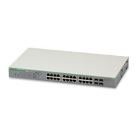
Allied Telesis AT-GS950/16PS Installation Manual (64 pages)
Allied Telesis Gigabit Ethernet PoE+ Switches
Brand:
Allied Telesis
| Category:
Network Router
| Size: 2.72 MB
Table of Contents
Installation Guide
1
Electrical Safety and Emissions Standards
3
Translated Safety Statements
4
Table of Contents
5
Preface
11
Symbol Conventions
12
Contacting Allied Telesis
13
Chapter 1 : Features
16
Twisted Pair Ports
16
SFP Slots
16
Leds
17
Installation Options
17
Power Conservation
17
MAC Address Table
17
Front and Back Panels
18
Figure 1: AT-GS950/10PS, AT-GS950/16PS, and AT-GS950/48PS Front Panels
18
Figure 2: AT-GS950/10PS Back Panel
19
Figure 3: AT-GS950/16PS Back Panel
19
Figure 4: AT-GS950/48PS Back Panel
19
Management Software
20
Twisted Pair Ports
21
Power over Ethernet (Poe)
22
Table 1. Max Ports Supported Per Poe Class
22
Combo Ports
23
Table 2. Combo Ports
23
Leds
24
PWR/SYS Leds
24
Figure 5: PWR LED on AT-GS950/10PS
24
Table 3. AT-GS950/10PS PWR LED Functional Descriptions
24
Figure 6: SYSTEM LED on AT-GS950/16PS
25
Figure 7: SYS LED on AT-GS950/48PS
25
Table 4. AT-GS950/16PS and AT-GS950/48PS SYS LED Functional Descriptions
25
10/100/1000 Baset Link Activity Leds
26
Figure 8: AT-GS950/10PS Link/Activity and Speed Leds
26
Table 5. AT-GS950/10PS L/A and SPD Leds Functional Descriptions
26
Figure 9: AT-GS950/16PS Link/Activity/Speed Leds
27
Figure 10: AT-GS950/48PS Link/Activity/Speed Port LED
27
SFP Leds
28
Figure 11: AT-GS950/10PS SFP Speed and Link/Activity Leds
28
Table 6. AT-GS950/16PS and AT-GS950/48PS L/A LED Functional Descriptions
28
Figure 12: AT-GS950/16PS SFP Status Leds
29
Figure 13: AT-GS950/48PS SFP Status Leds
29
Poe Leds
30
Table 7. SFP Slot LED Functional Descriptions
30
Figure 14: AT-GS950/10PS Poe and Poe MAX Leds
31
Figure 15: AT-GS950/16PS Poe and Poe MAX Leds
31
Figure 16: AT-GS950/48PS Poe and Poe MAX Leds
31
Table 8. Poe Status LED Functional Descriptions
31
Eco-Friendly Button
33
Eco-Friendly Button Operation
33
Figure 17: Eco-Friendly Button
33
Reboot/Reset the Switch
34
Power Supply
35
Fans
36
Chapter 2 : Reviewing Safety Precautions
38
Selecting a Site for the Switch
41
Cable Specifications
42
Table 9. Twisted Pair Cabling and Distances
42
Unpacking the Switch
43
Figure 18: Shipping Package Contents
44
Installing the Switch on a Desktop
45
Figure 19: Attaching the Rubber Feet
45
Installing the Switch in an Equipment Rack
46
Figure 20: Attaching the Rack-Mount Brackets to the Switch
46
Figure 21: Attaching the Rack-Mount Brackets to the Switch (Continued)
47
Figure 22: Mounting the Switch in an Equipment Rack
47
Installing the Switch on a Wall
48
Figure 23: Attaching the Brackets to Install the Switch on a Wall
48
Figure 24: Marking the Screw Hole Locations
49
Figure 25: Securing the Switch to the Wall
50
Installing Optional SFP Transceivers
51
Figure 26: Removing the Dust Plug from an SFP Slot
51
Figure 27: Inserting the SFP
52
Figure 28: Positioning the SFP Handle in the Upright Position
52
Cabling the Switch
54
Powering on the Switch
55
Figure 29: Plugging in the AC Power Cord
55
Troubleshooting
57
Chapter 3 : Appendix A: Physical Specifications
61
Dimensions
61
Weight
61
Table 10. Chassis Dimensions
61
Table 11. Chassis Weight
61
Environmental Specifications
62
Power Specifications
62
Poe Specifications
62
Table 12. Environmental Specifications
62
Table 13. Max AC Input Power Specifications
62
Table 14. Max Ports Supported Per Poe Class
62
Safety and Electromagnetic Emissions Certifications
63
Connectors and Port Pinouts
63
Figure 30: RJ-45 Connector and Port Pin Layout
63
Table 15. Safety and Electromagnetic Emissions Certifications
63
Table 16. MDI Pin Signals (10Base-T or 100Base-TX)
63
Table 17. MDI-X Pin Signals (10Base-T or 100Base-TX)
64
Table 18. RJ-45 1000Base-T Connector Pinouts
64
Advertisement
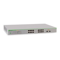
Allied Telesis AT-GS950/16PS User Manual (86 pages)
Gigabit Ethernet PoE Switches
Brand:
Allied Telesis
| Category:
Switch
| Size: 1.18 MB
Table of Contents
Table of Contents
3
Preface
5
Safety Symbols Used in this Document
6
Contacting Allied Telesis
7
Chapter 1: Introduction
9
GS950 PS Series of Gigabit Ethernet Poe+ Switches
10
Management Interfaces
11
Management Functions from the Command Line Interface
12
Command Line Interface Modes
13
Command Line Symbols
14
Starting a Command Line Management Session
15
Tips on Using the Command Line Interface
17
Chapter 2: Basic Management Commands
19
(Question Mark Key)
20
Clear Screen
21
Config Account
22
Configure Terminal
23
End
24
Logout
25
Reboot
26
Reset Config
27
Reset Config Except Ip
28
Save
29
Show Switch
30
Chapter 3: Ipv4 Management Address Commands
31
Config Ipif System
32
Config Ipif System Bootp
34
Config Ipif System Dhcp
35
Ping
36
Show Ipif
37
Chapter 4: Ipv6 Management Address Commands
39
Config Ipif System Dhcpv6_Client
40
Config Ipif System Ipv6
42
Ipv6 Address Link-Local
44
Ipv6 Automatic Link-Local Address
45
Ipv6 Enable
46
Ipv6 Gateway
47
No Ipv6 Enable
48
Ping6
49
Chapter 5: HTTP and HTTPS Commands
51
Ip Http Secure-Server
52
No Ip Http Secure-Server
53
Show Ip Http Secure-Server Status
54
Chapter 6: File Transfer Commands
55
Download
56
Upload
58
Chapter 7: SNMP Commands
59
No Snmp-Server Community
60
No Snmp-Server Engineid
61
No Snmp-Server Group
62
No Snmp-Server Host
64
No Snmp-Server Traps Enable
65
No Snmp-Server User
66
No Snmp-Server Viewtree
67
Show Snmp
68
Show Snmp Community
69
Show Snmp Engineid
70
Show Snmp Group
71
Show Snmp-Server Traps-Management
72
Show Snmp User
73
Show Snmp Viewtree
74
Snmp-Server Community
75
Snmp-Server Engineid
76
Snmp-Server Group
77
Snmp-Server Host
79
Snmp-Server Traps Enable
81
Snmp-Server User
82
Snmp-Server Viewtree
84
Allied Telesis AT-GS950/16PS Product Information (3 pages)
GS950 PS Series GIGABIT WEBSMART POE+ EDGE SWITCHES
Brand:
Allied Telesis
| Category:
Switch
| Size: 0.89 MB
Table of Contents
Key Features
1
Power over Ethernet
1
Specifications
2
Ordering Information
3
Allied Telesis AT-GS950/16PS Product Information (2 pages)
GS950 PS Series GIGABIT WEBSMART POE+ EDGE SWITCHES
Brand:
Allied Telesis
| Category:
Switch
| Size: 0.48 MB
Table of Contents
Key Features
1
High Performance
1
Specifications
2
Ordering Information
2
Advertisement
Related Products
Allied Telesis AT-GS950/16
Allied Telesis AT-GS950/24
Allied Telesis AT-GS950/8
Allied Telesis AT-GS950/8POE
Allied Telesis AT-GS950
Allied Telesis AT-GS950/48
Allied Telesis AT-GS950/48PS
Allied Telesis AT-GS950/10PS
Allied Telesis AT-GS950/28PS
Allied Telesis AT-GS900/8POE
Allied Telesis Categories
Switch
Network Router
Media Converter
Network Hardware
Wireless Access Point
More Allied Telesis Manuals
Login
Sign In
OR
Sign in with Facebook
Sign in with Google
Upload manual
Upload from disk
Upload from URL