Allied Telesis AT-GS950/8 Installation Manual
Gigabit ethernet smart switch
Hide thumbs
Also See for AT-GS950/8:
- User manual (364 pages) ,
- Installation manual (54 pages) ,
- Manual (44 pages)

Related Manuals for Allied Telesis AT-GS950/8


Summary of Contents for Allied Telesis AT-GS950/8
-
Page 1: Installation Guide
AT-GS950/8 AT-GS950/16 AT-GS950/24 AT-GS950/48 Gigabit Ethernet Smart Switch Installation Guide PN 613-001971 Rev. A... - Page 2 Telesis, Inc. be liable for any incidental, special, indirect, or consequential damages whatsoever, including but not limited to lost profits, arising out of or related to this manual or the information contained herein, even if Allied Telesis, Inc. has been advised of, known, or should have known, the possibility of such damages.
-
Page 3: Electrical Safety And Emissions Standards
Electrical Safety and Emissions Standards This product meets the following standards. U.S. Federal Communications Commission Radiated Energy Note: This equipment has been tested and found to comply with the limits for a Class A digital device pursuant to Part 15 of FCC Rules. -
Page 4: Translated Safety Statements
Translated Safety Statements Important: The indicates that translations of the safety statement are available in the PDF document “Translated Safety Statements” posted on the Allied Telesis website at www.alliedtelesis.com. -
Page 5: Table Of Contents
Contents Preface ................................11 Symbol Conventions ..........................11 Contacting Allied Telesis..........................12 Chapter 1 : Overview ............................. 13 Features ..............................13 Twisted Pair Ports ..........................13 LEDs..............................14 SFP Slots............................. 14 Installation Options ..........................14 Power Conservation ..........................14 MAC Address Table ..........................14 Management Software ........................ - Page 6 Contents Certifications............................... 49 Connectors and Port Pinouts........................50...
- Page 7 List of Figures Figure 1: AT-GS950/8, AT-GS950/16, AT-GS950/24 and AT-GS950/48 Front Panels ............16 Figure 2: Back Panel ................................17 Figure 3: Gigabit Ethernet to the Desktop Topology......................23 Figure 4: Gigabit Ethernet Backbone Topology........................24 Figure 5: AT-GS950/xx Packing List............................ 30 Figure 6: Attaching the Rubber Feet ...........................
- Page 8 List of Figures...
- Page 9 List of Tables Table 1. Combo Ports .................................18 Table 2. System LEDs ................................20 Table 3. 10/100/1000Base-T Port LEDs ..........................20 Table 4. SFP Slot LEDs ..............................21 Table 5. Twisted Pair Cabling and Distances ........................29 Table 6. Product Dimensions ..............................48 Table 7. Product Weights ..............................48 Table 8.
- Page 10 List of Tables...
-
Page 11: Preface
Preface This guide contains the installation instructions for the AT-GS950/8, AT-GS950/16, AT-GS950/24 and AT-GS950/48 Gigabit Ethernet Smart Switches. The overview gives a physical description of the switch hardware and the instructions give the installation procedures. This preface contains the following sections: ... -
Page 12: Contacting Allied Telesis
Preface Contacting Allied Telesis If you need assistance with this product, you may contact Allied Telesis technical support by going to the Support & Services section of the Allied Telesis web site at www.alliedtelesis.com/support. You can find links for the following services on this page: ... -
Page 13: Chapter 1 : Overview
“eco-friendly Button” on page 21 ❒ “Power Supply” on page 22 ❒ “Network Topologies” on page 23 Features Here are the hardware features of the AT-GS950/8, AT-GS950/16, AT- GS950/24 and AT-GS950/48 Gigabit Ethernet Switches. Twisted Pair ❒ 8, 16, 24 or 48 ports Ports ❒... -
Page 14: Leds
Speed and link/activity LEDs for the twisted pair ports ❒ Link/activity LEDs for the SFP slots ❒ Power LED SFP Slots ❒ Two slots on the AT-GS950/8 and AT-GS950/16 Switches ❒ Four slots on the AT-GS950/24 and AT-GS950/48 Switches ❒ Support 100Base-FX and 1000Base-SX/LX... -
Page 15: Management Software
AT-GS950/8, AT-GS950/16, AT-GS950/24 and AT-GS950/48 Switches Installation Guide Management ❒ AT-S107 Management Software for the AT-GS950/8 Switch Software ❒ AT-S108 Management Software for the AT-GS950/16 Switch ❒ AT-S109 Management Software for the AT-GS950/24 Switch ❒ AT-S116 Management Software for the AT-GS950/48... -
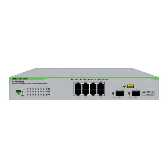
Page 16: Front And Back Panels
Chapter 1: Overview Front and Back Panels Figure 1 on page 16 illustrates the front panels of the AT-GS950/8, AT-GS950/16, AT-GS950/24 and AT-GS950/48 Gigabit Ethernet Switches. AT-GS950/8 eco-friendly Port and 10/100/1000Base-T SFP Slots System LEDs Button Twisted Pair Ports AT-GS950/16... -
Page 17: Management Software
Allied Telesis corporate web site and reinstall it on the switch. You may also want to periodically visit the Allied Telesis corporate web site to see if new versions of the software have been released. For instructions to install new management software, refer to the AT-S107, AT-S108, AT-S109 or AT- S116 Management Software User’s Guide. -
Page 18: Combo Ports
Auto-Negotiation and set the port’s speed and duplex mode manually. Combo Ports The AT-GS950/8 and AT-GS950/16 Switches have two combo ports. The AT-GS950/24 and AT-GS950/48 Switches has four combo ports. Each combo port consists of one 10/100/1000Base-T twisted pair port and one slot for an optional 100Base-FX or 1000Base-SX/LX SFP transceiver. - Page 19 AT-GS950/8, AT-GS950/16, AT-GS950/24 and AT-GS950/48 Switches Installation Guide Table 1. Combo Ports Switch Twisted Pair Port SFP Slot AT-GS950/48 The combo ports have the guidelines listed here: ❒ Only one port in a pair — either the twisted pair port or a corresponding SFP module —...
-
Page 20: Leds
The operating speed of the port is 10 Mbps or the port has not established a link with a network device. DPX (duplex mode Steady The port is operating in full duplex mode. for AT-GS950/8 Green Switch only) The port is operating in half duplex mode. -
Page 21: Eco-Friendly Button
AT-GS950/8, AT-GS950/16, AT-GS950/24 and AT-GS950/48 Switches Installation Guide Table 4 describes the LEDs for the SFP slots. Table 4. SFP Slot LEDs State Description The port on the SFP transceiver has not established a link with an end node or the transceiver slot is empty. -
Page 22: Power Supply
❒ Both the reboot and factory default reset functions can be disabled in the management software. For more information, refer to the AT-GS950/8, AT-GS950/16, or AT-GS950/24 Management Software User’s Guide. Power Supply Each switch has an internal power supply with a single AC power supply socket on the back panel. -
Page 23: Network Topologies
AT-GS950/8, AT-GS950/16, AT-GS950/24 and AT-GS950/48 Switches Installation Guide Network Topologies This section illustrates two network topologies: Gigabit Ethernet to the desktop and Gigabit Ethernet backbone. Gigabit Ethernet The topology shown in Figure 3 is commonly referred to as Gigabit Ethernet to the desktop. This topology provides the best in performance... -
Page 24: Figure 4: Gigabit Ethernet Backbone Topology
Chapter 1: Overview Legend 10 Mbps 100 Mbps 1000 Mbps Figure 4. Gigabit Ethernet Backbone Topology... -
Page 25: Chapter 2 : Installation
AT-GS950/8, AT-GS950/16, AT-GS950/24 and AT-GS950/48 Switches Installation Guide Chapter 2 Installation This chapter contains the following sections: ❒ “Reviewing Safety Precautions” on page 26 ❒ “Selecting a Site for the Switch” on page 28 ❒ “Cable Specifications” on page 29 ❒... -
Page 26: Reviewing Safety Precautions
indicates that a translation of the safety statement is available in a PDF document titled “Translated Safety Statements” posted on the Allied Telesis website at alliedtelesis.com/support. Warning To prevent electric shock, do not remove the cover. No user- serviceable parts inside. This unit contains hazardous voltages and should only be opened by a trained and qualified technician. - Page 27 AT-GS950/8, AT-GS950/16, AT-GS950/24 and AT-GS950/48 Switches Installation Guide Caution Operating Temperature. This product is designed for a maximum ambient temperature of 40 degrees C. Note All Countries: Install product in accordance with local and National Electrical Codes. Note...
-
Page 28: Selecting A Site For The Switch
Chapter 2: Installation Selecting a Site for the Switch Observe the following requirements when choosing a site for your switch: ❒ If you plan to install the switch in an equipment rack, verify that the rack is safely secured and will not tip over. Devices in a rack should be installed starting at the bottom, with the heavier devices near the bottom of the rack. -
Page 29: Cable Specifications
AT-GS950/8, AT-GS950/16, AT-GS950/24 and AT-GS950/48 Switches Installation Guide Cable Specifications Table 5 contains the cable specifications for the twisted pair ports. Table 5. Twisted Pair Cabling and Distances Maximum Speed Type of Cable Operating Distance 10 Mbps Standard TIA/EIA 568-B-compliant... -
Page 30: Unpacking The Switch
2. Place the switch on a level, secure surface. 3. Verify that the shipping container includes the items listed in Figure 5 on page 30 in addition to your AT-GS950/8, AT-GS950/16, AT-GS950/ 24 or AT-GS950/48 switch. Two equipment rack or... -
Page 31: Installing The Switch On A Desktop
AT-GS950/8, AT-GS950/16, AT-GS950/24 and AT-GS950/48 Switches Installation Guide Installing the Switch on a Desktop You may install the AT-GS950 Switch on a desktop or in a standard 19- inch equipment rack. To install the switch in a rack, refer to “Installing the Switch in an Equipment Rack”... -
Page 32: Installing The Switch In An Equipment Rack
Chapter 2: Installation Installing the Switch in an Equipment Rack To install the switch in a standard 19-inch equipment rack, perform the following procedure: 1. If the rubber feet are attached to the bottom of the switch, remove them using a flat-head screwdriver. 2. -
Page 33: Figure 7: Attaching The Rack-Mount Brackets To The Switch
AT-GS950/8, AT-GS950/16, AT-GS950/24 and AT-GS950/48 Switches Installation Guide Figure 7. Attaching the Rack-Mount Brackets to the Switch... -
Page 34: Figure 8: Mounting The Switch In An Equipment Rack
Chapter 2: Installation 3. Mount the switch in a standard 19-inch equipment rack using four equipment rack screws (not provided with the switch). Figure 8. Mounting the Switch in an Equipment Rack 4. Go to “Installing Optional SFP Transceivers” on page 37 or “Cabling the Switch”... -
Page 35: Installing The Switch On A Wall
AT-GS950/8, AT-GS950/16, AT-GS950/24 and AT-GS950/48 Switches Installation Guide Installing the Switch on a Wall To install the switch on a wall, perform the following procedure: 1. Turn the switch over and place it on a table. 2. If the rubber feet are attached to the bottom of the switch, remove them using a flat-head screwdriver. -
Page 36: Figure 11: Securing The Switch To The Wall
Chapter 2: Installation 5. Install the four plastic anchors included with the switch into the wall, at the locations marked in the previous step. The anchors require 0.635 mm (0.25 in.) holes. 6. While another person holds the switch at the wall location, secure it to the wall using the four wall mounting screws. -
Page 37: Installing Optional Sfp Transceivers
AT-GS950/8, AT-GS950/16, AT-GS950/24 and AT-GS950/48 Switches Installation Guide Installing Optional SFP Transceivers To install an SFP transceiver, perform the following procedure: Note The transceiver can be hot-swapped; you do not need to power off the switch to install a transceiver. However, always remove the cables before removing the transceiver. -
Page 38: Figure 13: Inserting The Sfp
Chapter 2: Installation 4. Slide the transceiver into the SFP slot until it clicks into place. See Figure 13 Figure 13. Inserting the SFP 5. Verify that the handle on the transceiver is in the upright position, as shown in Figure 14. This secures the transceiver and prevents it from being dislodged from the slot. - Page 39 AT-GS950/8, AT-GS950/16, AT-GS950/24 and AT-GS950/48 Switches Installation Guide For information on the cable specifications of the SFP, consult the documentation shipped with the SFP. 7. Go to “Cabling the Switch” on page 40.
-
Page 40: Cabling The Switch
Chapter 2: Installation Cabling the Switch Observe the following guidelines when connecting twisted pair and fiber optic cables to the ports on the switch: ❒ The connector on the cable should fit snugly into the port on the switch. The tab on the connector should lock the connector into place. -
Page 41: Powering On The Switch
AT-GS950/8, AT-GS950/16, AT-GS950/24 and AT-GS950/48 Switches Installation Guide Powering On the Switch To power on the switch, perform the following procedure: 1. Plug the power cord into the AC power connector on the back of the switch, as shown in Figure 15. - Page 42 Chapter 2: Installation...
-
Page 43: Chapter 3 : Troubleshooting
This chapter contains information on how to troubleshoot the switch if a problem occurs. Note For further assistance, please contact Allied Telesis Technical Support at www.alliedtelesis.com/support. Problem 1: The POWER LED on the front of the switch is off. Solutions: The unit is not receiving power. Try the following: ❒... - Page 44 Chapter 3: Troubleshooting ❒ Try connecting another network device to the twisted pair port with a different cable. If the twisted pair port is able to establish a link, then the problem is with the cable or the other network device. ❒...
- Page 45 Solution: There might be a duplex mode mismatch between the port and the network device. This occurs when a twisted pair port using Auto- Negotiation is connected to a device with a fixed duplex mode of full duplex. If this is the cause of the problem, adjust the duplex mode of the port on the network device or on the switch so that both ports are using the same duplex mode.
- Page 46 Chapter 3: Troubleshooting...
-
Page 47: Appendix A: Technical Specifications
Appendix A Technical Specifications This appendix contains the technical specifications for the AT-GS950/8, AT-GS950/16, AT-GS950/24 and AT-GS950/48 switches. The specification categories are as follows: “Physical Specifications” on page 48 “Environmental Specifications” on page 49 “Power Specifications” on page 49 “Certifications” on page 49... -
Page 48: Physical Specifications
Physical Specifications Dimensions (H x W x D) Table 6. Product Dimensions Model Specification AT-GS950/8 33 cm x 20 cm x 4.4 cm (13 in x 7.87 in x 1.73 in) AT-GS950/16 33 cm x 20 cm x 4.4 cm (13 in x 7.87 in x 1.73 in) -
Page 49: Environmental Specifications
5% to 90% noncondensing Storage Humidity 5% to 95% noncondensing Power Specifications Input Supply Voltage - 100-240 VAC, 50 - 60 Hz Table 9. Max AC Input Power Specifications Parameter Specifications AT-GS950/8 8.7 W AT-GS950/16 12.9 W AT-GS950/24 17.3 W AT-GS950/48 43.0 W Certifications Table 10. -
Page 50: Figure 15: Rj-45 Connector And Port Pin Layout
Appendix A: Technical Specifications Connectors and Port Pinouts This section lists the connectors and connector pinouts. Figure 16 illustrates the pin layout for an RJ-45 connector and port. Figure 16. RJ-45 Connector and Port Pin Layout Table 11 lists the RJ-45 pin signals when a twisted pair port is operating in the MDI configuration. -
Page 51: Table 13. Rj-45 1000Base-T Connector Pinouts
Table 13 lists the RJ-45 connector pins and their signals when a 1000Base-T port is operating at 1000 Mbps. Table 13. RJ-45 1000Base-T Connector Pinouts Pair Signal TX and RX+ TX and RX- TX and RX+ TX and RX+ TX and RX- TX and RX- TX and RX+ TX and RX-... - Page 52 Appendix A: Technical Specifications...
Need help?
Do you have a question about the AT-GS950/8 and is the answer not in the manual?
Questions and answers