Sign In
Upload
Manuals
Brands
Agilent Technologies Manuals
Measuring Instruments
E8362A
Agilent Technologies E8362A Manuals
Manuals and User Guides for Agilent Technologies E8362A. We have
2
Agilent Technologies E8362A manuals available for free PDF download: Service Manual, Installation And Quick Start Manual
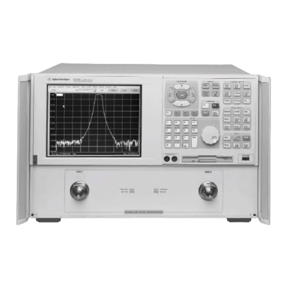
Agilent Technologies E8362A Service Manual (335 pages)
PNA Series Microwave Network Analyzers
Brand:
Agilent Technologies
| Category:
Measuring Instruments
| Size: 10.02 MB
Table of Contents
Service Guide E8364-90001
3
Information in this Chapter
12
Safety Symbols
13
Servicing
14
Electrostatic Discharge Protection
15
Regulatory Information
16
Compliance with Canadian EMC Requirements
17
Information in this Chapter
20
Maintenance
21
Option 099, Firmware Upgrade
22
Option 0BW, Printed Service Guide
23
Required Service Test Equipment
24
Agilent Support, Services, and Assistance
27
Service and Support Options
28
Information in this Chapter
30
Before You Begin
32
Review the Principles of Connector Care
33
About System Verification and Performance Tests
34
System Verification Procedure
35
ANSI/NCSL Z540–1–1994 Verification
36
Non-ANSI/NCSL Z540–1–1994 Verification
37
Preliminary Checks
38
The Test Port Cable Checks
41
System Verification
48
Measurement Uncertainty
49
Measurement Traceability
50
Performing System Verification
51
Performance Tests (Agilent N2721A Software Package)
58
Source Power Linearity Test
59
Trace Noise Test
60
Noise Floor Test
61
Calibration Coefficient Test
62
System Crosstalk Test
63
Power Meter Accuracy Test
65
Adjustments
70
Source Calibration Adjustment
71
Receiver Calibration Adjustment
72
LO Power Adjustment
75
Mhz Frequency Reference Adjustment
77
Ghz PMYO Frequency Adjustment
78
Information in this Chapter
80
Protect against Electrostatic Discharge (ESD)
81
Getting Started with Troubleshooting
82
Troubleshooting Organization
83
Power up Troubleshooting
84
Power Supply Check
85
Troubleshooting LCD Display Problems
91
Front Panel Troubleshooting
95
A2 Display Test
97
A3 Front Panel Interface Board
98
Rear Panel Troubleshooting
99
Checking the GPIB Port
100
LAN Troubleshooting
101
Measurement System Troubleshooting
105
Verifying the A, B, R1, and R2 Traces
106
Where to Begin Troubleshooting
107
Checking the Source Group
110
Checking the Signal Separation Group
124
Checking the Receiver Group
128
Instrument Block Diagrams
131
E8362A Overall Block Diagram, Includes Options UNL and 014
133
E8363A and E8364A, Includes Option UNL
135
E8363A and E8364A, Includes Options UNL and 014
137
Information in this Chapter
140
Network Analyzer System Operation
141
Source Group Operation
143
A8 Fractional-N Synthesizer Board
145
A17 L.O. Multiplier/Amplifier 10 (LOMA 10)
146
A11 Phase Lock Board
147
A21 Source Multiplier/Amplifier 50 (SOMA 50) (E8363A and E8364A Only)
148
A16 Test Set Motherboard
149
Signal Separation Group Operation
153
A23 and A24 Detectors (E8363A and E8364A Only)
154
Option 014 Configurable Test Set
155
Receiver Group Operation
158
A6 SPAM Board (Analog Description)
160
Digital Processing and Digital Control Group Operation
161
Front Panel Subgroup
163
Data Acquisition and Processing Subgroup
164
Power Supply Group Operation
167
Information in this Chapter
170
Ordering Information
171
Assembly Replacement Sequence
172
Rebuilt-Exchange Assemblies
173
Replaceable Parts Listings
174
Front Panel Assembly
178
Top Assemblies and Hardware
180
Bottom Assemblies, Standard
182
Bottom Assemblies, Option UNL
184
Bottom Assemblies, Option 014
186
Bottom Assemblies, Option UNL, 014
188
Bottom Hardware
190
Top Cables
192
Bottom RF Cables, Standard
194
Bottom RF Cables, Option UNL
196
Bottom RF Cables, Option 014
198
Bottom RF Cables, Option 014 (Continued)
199
Bottom RF Cables, Option UNL, 014
201
Bottom RF Cables, Option UNL, 014 (Continued)
202
Bottom Cables, Ribbon and Wrapped-Wire
204
Internal Hardware and Parts
206
Hard Disk Drive Assembly
208
Rear Panel Assembly
209
External Parts
210
Miscellaneous Part Numbers
212
Miscellaneous Part Numbers (Continued)
213
Information in this Chapter
216
Before Starting the Removal and Replacement Procedures
217
Removal and Replacement Procedures
218
Removing the Covers
220
Raising and Removing the Receiver Deck
222
Removing and Replacing the Front Panel Assembly
224
Removing and Replacing Front Panel Subassemblies
226
Removing and Replacing the Display Inverter Board and the Display Lamp
228
Removing and Replacing the A4 Power Supply Assembly
230
Removing and Replacing the A6, A8, and A10 Boards
232
Removing and Replacing the A11 Phase Lock Board
234
Removing and Replacing the A12 Source 20
236
Removing and Replacing the A14 System Motherboard
238
Removing and Replacing the A15 CPU Board
240
Removing and Replacing the A16 Test Set Motherboard
242
Removing and Replacing the A17 LOMA 10
244
Removing and Replacing the A18 MA 20
246
Removing and Replacing the A19 Splitter
248
Removing and Replacing the A20 LODA
250
Removing and Replacing the A21 SOMA 50 (E8363A and E8364A Only)
252
Removing and Replacing the A22 Switch Splitter
254
Removing and Replacing the 30-Db Fixed Attenuators (E8362A Only)
256
Removing and Replacing the A23 and A24 Detectors (E8363A and E8364A Only)
258
Removing and Replacing the A25 and A26 Test Port Couplers
260
Bias Board
262
Removing and Replacing the A31, A32, A33, and A34 Receiver Modules
264
Removing and Replacing the A35 Receiver Motherboard
266
Removing and Replacing the A36 and A37 60-Db Step Attenuators (Option UNL)
268
Removing and Replacing the A38 and A39 Bias Tees (Option UNL)
270
Removing and Replacing the A40 Floppy Disk Drive
272
Removing and Replacing the A41 Hard Disk Drive
274
Tools Required
275
Removing and Replacing the Midweb and the B1 Fan
281
Post-Repair Procedures
284
Information in this Appendix
288
Using Error Terms as a Diagnostic Tool
289
Performing Measurement Calibration
290
Accessing Error Terms
292
Programmatic Access to Error Terms
293
Error Term Data
294
If Error Terms Seem Worse than Expected
295
Information in this Appendix
304
Accessing the Option Enable Utility
305
Installing or Removing Options
306
Repairing and Recovering Option Data
307
Installing or Changing a Serial Number
308
Information in this Appendix
310
Downloading Using Option 099, Firmware Upgrade
311
Downloading over the LAN
312
Information in this Appendix
314
System Recovery Procedure
316
If the Operating System Does Not Boot from the Hard Disk Drive
317
If the Operating System Does Not Boot from the Floppy Disk Drive
318
Advertisement
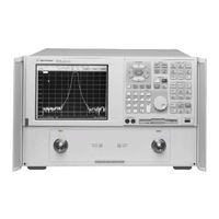
Agilent Technologies E8362A Installation And Quick Start Manual (24 pages)
Network Analyzers
Brand:
Agilent Technologies
| Category:
Measuring Instruments
| Size: 0.49 MB
Table of Contents
Table of Contents
4
1 Installing Your Analyzer
5
STEP 1. Check the Shipment
5
STEP 2. Meet Electrical and Environmental Requirements
8
STEP 3. Install the Analyzer on a Bench Top or in an Equipment Rack
9
To Install on a Bench Top
9
To Install in an Equipment Rack
9
STEP 4. Connect the Accessories
10
STEP 5. Install Ferrite Cores
11
STEP 6. Start up the Analyzer
12
STEP 7. Perform Administrative Tasks
13
STEP 8. Run the Operator's Check
14
STEP 9. Turn off the Analyzer
14
To Hibernate the Analyzer
14
To Shut down the Analyzer
15
2 Getting Help with Your Analyzer
17
Contacting Agilent Technologies
17
Help System
17
PNA on the Internet
18
Product Overview
18
3 Safety and Regulatory Information
19
Maintenance
19
Shipment for Service
19
Safety Symbols
19
General Safety Considerations
20
Safety Earth Ground
20
Before Applying Power
20
Servicing
21
Regulatory Information
21
Instructions for Use
21
Instrument Markings
22
Declaration of Conformity
23
Compliance with German Noise Requirements
24
Warranty
24
Advertisement
Related Products
Agilent Technologies E8362C
Agilent Technologies E8362B
agilent technologies E8362A PNA Series
Agilent Technologies E8362
Agilent Technologies E8362BH85PNA Series
Agilent Technologies E8363C
Agilent Technologies E8364A
Agilent Technologies E8363BU-014
Agilent Technologies E8364-90019
Agilent Technologies E8364-60103
Agilent Technologies Categories
Measuring Instruments
Laboratory Equipment
Test Equipment
Water Pump
Power Supply
More Agilent Technologies Manuals
Login
Sign In
OR
Sign in with Facebook
Sign in with Google
Upload manual
Upload from disk
Upload from URL