
Related Manuals for Konica Minolta CL-70F


Summary of Contents for Konica Minolta CL-70F
-
Page 1: Operating Manual
CRI Illuminance Meter CL-70F Operating Manual Please read the operating manual carefully to fully understand the features of this product before use and keep it for future use. Keep the operating manual in a safe place. - Page 2 Congratulations on your purchase of a Konica Minolta CRI Illuminance Meter CL-70F. Please read the operating manual carefully to properly utilize the many features and benefits of this precision instrument. The Konica Minolta CRI Illuminance Meter CL-70F is a portable spectrometer equipped with CMOS linear image sensor that can measure from 380nm to 780nm.
-
Page 3: Safety Precautions
■ Safety Precautions Before using this product, please read this "Safety Precautions" for proper operation. WARNING The WARNING symbol indicates the possibility of death or serious injury if the product is not used properly. CAUTION The CAUTION symbol indicates the possibility of minor to moderate personal injury or product damage if the product is not used properly. - Page 4 WARNING ● Infants or toddlers may accidentally wrap the strap around their neck, so please place it in a location out of their reach. There is a danger of suffocation. ● Do not place batteries in open flames, attempt to short, disassemble or apply heat to them, use unspecified batteries, or recharge them (except rechargeable batteries).
-
Page 5: Polyvinyl Chloride (Pvc) Cable And Cord Notice
■ Polyvinyl Chloride (PVC) cable and cord notice WARNING Handling the cords associated with accessories sold with this product will expose you to lead, a chemical known to the State of California to cause cancer, and birth defects or other reproductive harm. Wash hands after handling. - Page 6 NOTICE ● A protective sheet is attached to the LCD. Peel it off before use. ● Although the LCD monitor is manufactured to very high standards, it is possible to observe a few dead pixels on the screen. This is normal and not a malfunction of the meter.
-
Page 7: Intended Usage
Controlling the illuminance and monitoring spectral distribution of light source for indoor agriculture. Evaluating the illuminance, color temperature, and color rendering index of road ● lighting, indoor lighting, store lighting, and others. Main features of the CL-70F Model name Usage Features CL-70F... -
Page 8: Intended Users
■ Intended Users The intended users of this product are the following. ● People monitoring and quality control of LED, OLED, projector illumination, etc. People monitoring and management of illumination during installation and use of ● lamps used in museums, restaurants, work spaces, etc. ●... -
Page 9: Accompanying Accessories
■ Accompanying Accessories The following items are included with the CRI Illuminance Meter CL-70F. Confirm if any accessories are missing after unpacking. If something is missing, contact the sales agent. Batteries (size AA) and a USB cable are not included. -
Page 10: Table Of Contents
Table of Contents ■ Safety Precautions ............................ ■ Polyvinyl Chloride (PVC) cable and cord notice i ii ................ ■ Intended Usage ............................ ■ Intended Users ............................ ■ Restrictions .............................. ■ Accompanying Accessories v ii ... - Page 11 4-3-2 Displaying in Spectrum Graph [Spectrum] Mode ............ 4-3-3 Displaying in Spectrum Comparison [Spectrum Comp.] Mode ......... 4-3-4 Displaying in Color Rendering Index [CRI] Mode ............ 4-3-5 Displaying in CIE1931 (CIE1964) [CIE1931 (CIE1964)] Mode ......... 4-3-6 Displaying in CIE1931 (CIE1964) Comparison [CIE1931 (CIE1964) Comp.] Mode ...
- Page 12 7-2-3 Selecting the Auto Power Off Time 1 13 ................... 7-2-4 Selecting the Backlight Brightness 1 15 ................... 7-2-5 Selecting the Auto Dimmer Time 1 17 .................. 7-2-6 Selecting the Language 1 19 ...................... 7-2-7 Reset Customized Items 1 21 ...
-
Page 14: Parts Designations And Functions
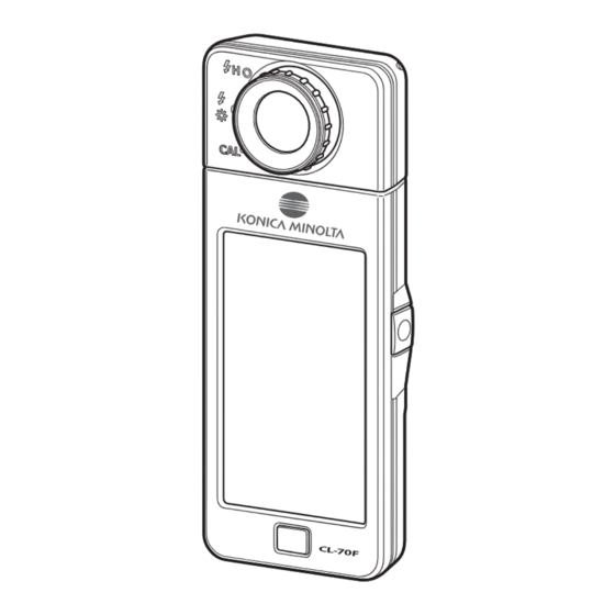
1. Parts Designations and Functions Parts Designations and Functions 1-1 Parts Designations Front View Rear View Light Receptor Light Selection Ring Power Button Display Panel Measuring Button Tripod Socket Memory Button Battery Cover Latch Battery Cover Menu Button Bottom View Battery Compartment Section Strap Eyelet Sync Terminal... -
Page 15: Parts Functions
1. Parts Designations and Functions 1-2 Parts Functions The following table lists the functions of each part. Part Name Functions Point light receptor directly at light source during reading. Head Light Receptor rotates 270 degrees to aid reading. Light Selection Rotate to select dark calibration, normal measuring range or high Ring range for flash light. -
Page 16: Before Use
2. Before Use Before Use 2-1 Attaching the Strap Pass the strap (included) through the outer hole of the Strap Eyelet c. Pass the opposite end of the strap through the loop at the end of the strap. Strap Eyelet WARNING Infants or toddlers may accidentally wrap the strap around their neck, so please place it in a location out of their reach. -
Page 17: Installing The Batteries
2. Before Use 2-2 Installing the Batteries Prepare two AA batteries. Slide the Battery Cover Latch in the direction of the arrow and remove the Battery Cover 9. Insert the batteries according to the "+" and "-" symbols in the Battery Compartment d. -
Page 18: Power On/Off
2. Before Use 2-3 Power ON/OFF Power ON Light Selection Ring Turn the Light Selection ing to set to the dark calibration position Press the Power Button 3. The meter will turn on and the Opening screen will be displayed (for 2 seconds). Power Button CL-7 F Opening Screen NOTICE... - Page 19 2. Before Use Select the language. (Appears only when turned O for the first time) The Language Selection screen is displayed. Select the language to use. Language Selection Language Selection Screen Confirmation Screen A blue highlight will appear behind the selected button.
- Page 20 2. Before Use NOTICE ● When the Light Selection ing is not set to the dark Dark Calibration Position Confirmation Screen calibration position, the message "Please set Light Selection Ring for dark calibration." is displayed. Set the Light Selection ing to the dark calibration position ) to calibrate the system.
- Page 21 2. Before Use NOTICE When the Measuring Button is pressed at the dark calibration position, the message "Measurement failed. Please check Light Selection ing position." is displayed. Turn the Light Selection ing to select the range. NOTE Measurement and display will take longer in light levels below 30lx. The LCD illumination will normally switch off during measurement to avoid influence to measurement.
-
Page 22: Checking The Battery Capacity
2. Before Use 2-4 Checking the Battery Capacity When the power is turned ON, the LCD screen will show the battery capacity indicator. Sufficient battery life remaining. Battery capacity indicator Adequate battery life remaining. Have a spare battery ready. Replace the battery immediately. NOTE ●... -
Page 23: Automatic Power Off Function
2. Before Use 2-5 Automatic Power OFF Function To save battery capacity, the meter will automatically turn off 5 minutes (factory setting) after the last button is pressed. NOTE ● All measurements, settings and indications are saved in memory even after the meter has automatically turned off. When the power is turned ON, they will be displayed again. -
Page 24: Changing Batteries During Measurement
2. Before Use 2-6 Changing Batteries During Measurement ● Please make sure the power is OFF when replacing batteries. If left ON, the meter circuit could be damaged and measurements taken during the last operation will not be saved. If an unexpected display appears on the LCD during battery replacement or ●... -
Page 25: Basic Operation Methods
3. Basic Operation Methods Basic Operation Methods 3-1 Basic Operation Flow The basic operations and screens are as follows. Measurements and measurement changes are operated from the Measurement screen. Power ON Opening Screen Language Selection (for first time only) Make sure the Light Selection Dark Calibration Ring is set to the dark... - Page 26 3. Basic Operation Methods From the previous page [Measuring Mode] Icon Select the measuring mode. Measuring Mode Selection Screen Ambient Light, Flash Light (Cordless, Cord) Measurement Screen Measuring Icon Measuring The LCD dims when measuring. Measuring Screen When measurement is complete, the LCD returns to the Measurement Screen previous user set brightness,...
-
Page 27: Screen And Operation
3. Basic Operation Methods 3-2 Screen and Operation 3-2-1 Basic Screen and Operation The touch-screen display enables selecting Display Modes and settings with the touch of your finger. Measurement Screen The Measurement screen is displayed (for 2 seconds) after the power is turned ON, and the dark calibration is made. - Page 28 3. Basic Operation Methods Item List Part ame Description Status Bar Displays the setting contents. ( P16) Displays the measuring mode. ( P22) [Measuring Mode] Icon Switches to the Measuring Mode Selection screen. Displays the display mode. ( P28) Switches to the [Display Mode] Icon Display Mode Selection screen.
- Page 29 3. Basic Operation Methods Status Bar For this description, all icons and menus are displayed. Part ame Description Sufficient battery life remaining. Adequate battery life remaining. Battery Capacity Have a spare battery ready. Indicator Replace the battery immediately. Appears when powered by USB. Displays the number of measured data stored in memory.
- Page 30 3. Basic Operation Methods Tool Box Screen The following setting can be performed after touching the [Tool Box ( )] icon on the measuring screen. * All icons are displayed for explanatory purposes for the Tool Box screen. It is not the default.
-
Page 31: Icon Operation
3. Basic Operation Methods 3-2-2 Icon Operation Touch Operation Touch the icons on screen to perform various operations. (Ex.) Measuring Screen in Text Mode Touch-enabled Icons A blue illumination under icons indicates which icons are operational. Touch-enabled Icons Touch-disabled Icons Slide Operation Slide your finger tip up or down over a value to change the value amount. -
Page 32: Input Of Numbers/Characters
3. Basic Operation Methods 3-2-3 Input of umbers Characters You can input numbers and characters. umeric umber Input Screen (Ex.) Display of deviation umeric umber Method Description Enters a numeric value, plus or minus sign, and a period. When touched, -, period the entry is displayed at the top of the screen. - Page 33 3. Basic Operation Methods Character Input Screen Figure Input Screen Upper Case Input Screen Lower Case Input Screen (Figures) (Upper Case Letters) (Lower Case Letters) eypad (Upper Case Input Screen) eypad (Lower Case Input Screen) Input Method of Characters and umbers Description 1 A a Shifts between numbers/upper case letters/lower case letters.
-
Page 34: Locking And Unlocking The Screen
3. Basic Operation Methods 3-2-4 Locking and Unlocking the Screen You can lock the screen to prevent misoperation. When the screen is locked, touch operation is disabled. However, the Memory Button , Measuring Button , and Power Button are still operational. -
Page 35: Setting The Measuring Conditions
4. Setting the Measuring Conditions Setting the Measuring Conditions 4-1 Selecting the Measuring Mode 4-1-1 Matching Measuring Mode with Light Sources Select the Measuring Mode to use. NOTICE When changing the measuring mode setting, the measurement data will be erased. Measuring Mode Selection Screen Measuring Mode Icon... - Page 36 4. Setting the Measuring Conditions Operation Touch the [Measuring Mode] icon in the upper left corner of the screen. The Measuring Mode Selection screen will be displayed. Measuring Screen Measuring Mode in Text Mode Selection Screen [Measuring Mode] Icon Touch an icon to select the measuring mode. Select the desired measuring mode.
-
Page 37: Selecting The Exposure Time (Ambient Modes Only)
Touch Cancel to return to the previous measurement screen without setting. Exposure time is set. NOTE In uto mode, the CL-70F automatically selects among measuring times, determined by the illumination available, to achieve a proper result in a convenient way. -
Page 38: Selecting The Shutter Speed (Flash Modes Only)
4. Setting the Measuring Conditions 4-1-3 Selecting the Shutter Speed (Flash Modes Only) Set a shutter speed that is appropriate for the intended flash-ambient measurement. Operation Touch the [Shutter Speed] indication. Measuring Screen in Text Mode Te t Mode in Cordless Mode Select the desired shutter speed. - Page 39 4. Setting the Measuring Conditions NOTE Shutter Speed Options 1 Step NOTICE ● When measuring flash-light color in high ambient light conditions (64 lx·s or higher), select a shutter speed of 1/250 or 1/500 sec to reduce or eliminate the influence of the ambient light in the measurement. Using slower shutter speeds will include ambient light color in the measurement.
-
Page 40: Customizing Measuring Displays
4. Setting the Measuring Conditions 4-2 Customizing Measuring Displays The meter s display can be customi ed to show only items you need in a single view. Operation Touch the [Display Item] indication on the Measurement screen. The Display item library screen will be displayed. ( P33) Select the items to be displayed. -
Page 41: Selecting The Display Mode
4. Setting the Measuring Conditions 4-3 Selecting the Display Mode Touching an icon on the isplay Mode Selection screen displays lighting information in different ways to suit your needs. * Pressing the Menu Button returns the screen to the isplay Mode Selection. Display Mode Selection Screen (2°) Display Mode Selection Screen (10°) Text... - Page 42 4. Setting the Measuring Conditions Display Mode Icons List Description Icon Display Mode Name isplays user-selected items in [Text] Icon numeric values. P32) isplays user-selected values and [Spectrum] Icon spectrum distribution graph. P35) Compares the current measurement [Spectrum Comparison] value and up to memori ed values Icon in the spectrum distribution graph.
- Page 43 4. Setting the Measuring Conditions Operation Touch the [Display Mode] icon on the Measurement screen or press Menu Button on the meter. The Display Mode Selection screen will be displayed. ( P28) isplay modes from o. to are for measurement. isplay mode o.
- Page 44 4. Setting the Measuring Conditions Press the Measuring Button to measure. Light Selection Ring The Light Selection Ring should be set to L when ta ing ambient light measurements. When measuring flash units, select Range L or Range ) depending on the brightness of Light the flash.
-
Page 45: Displaying In Text [Text] Mode
4. Setting the Measuring Conditions 4-3-1 Displaying in Text [Text] Mode ou can select items to display on the Te t Screen. Text Screen [Measuring Mode] Icon isplay Mode Icon Te t isplay posure Time Indication isplay Item Indication Operation Touch the [Text] icon on the Display Mode screen. - Page 46 4. Setting the Measuring Conditions Touch the [Display Item] indication to change. The Display item library screen will be displayed. The currently selected display item will be encircled in blue. Touch the desired Display Item indication and [OK] button. Confirms the settings, and returns to the Text screen. To return to the Te t screen without changing, touch the Cancel button.
- Page 47 4. Setting the Measuring Conditions Touch the [Exposure Time] indication in the Measurement screen. Set the exposure time to Auto, 0.1 sec, or 1.0 sec during ambient light measurement. ( P24) Press the Measuring Button to measure. Light Selection Ring The Light Selection Ring should be set to L when ta ing ambient light measurements.
-
Page 48: Displaying In Spectrum Graph [Spectrum] Mode
4. Setting the Measuring Conditions 4-3-2 Displaying in Spectrum Graph [Spectrum] Mode isplays three user-selected values and spectral distribution graph. Spectrum Screen [Measuring Mode] Icon isplay Mode Icon Spectrum isplay posure Time Indication isplay Item Indication Operation Touch the [Spectrum] icon on the Display Mode screen. A spectrum distribution graph screen will be displayed. - Page 49 4. Setting the Measuring Conditions Press the Measuring Button to measure. Light Selection Ring The Light Selection Ring should be set to L when ta ing ambient light measurements. When measuring flash units, select Range L or Range ) depending on the brightness of the flash.
- Page 50 4. Setting the Measuring Conditions NOTE The ma imum display value of the -a is can be selected by the item Spectrum -a is Scale icon in page of Setting. Memorize the measurement results. Measurement results can be memorized. To record measurements, press Memory utton...
-
Page 51: Displaying In Spectrum Comparison [Spectrum Comp.] Mode
4. Setting the Measuring Conditions 4-3-3 Displaying in Spectrum Comparison [Spectrum Comp.] Mode isplays the current measured value plus up to two selected values from the meter s memory for comparison. Spectrum Comp. Screen posure Time Indication isplay Mode Icon [Measuring Mode] Icon Spectrum Comparison isplay... - Page 52 4. Setting the Measuring Conditions Press the Measuring Button to measure. Light Selection Ring The Light Selection Ring should be set to L when ta ing ambient light measurements. When measuring flash units, select Range L or Range ) depending on the brightness of the flash.
- Page 53 4. Setting the Measuring Conditions If no measurements have been memorized, a message will be displayed to indicate this pop-up screen. Memory Selection Pop-up Screen fter you confirmed the message " o memori ed value.", touch the Close button. Returns to the Spectrum Comp. screen. NOTE See the "...
- Page 54 4. Setting the Measuring Conditions Touch the [OK] button. Confirms the setting and returns to the Spectrum Comp. screen. To cancel the setting, touch the Cancel button. The titles and measurements of the selected memories will be displayed on the Spectrum Comp. screen. Memory Title Display Memory Title Memori ed Measurement alue...
- Page 55 4. Setting the Measuring Conditions Touch the [Magnifying Glass (+)] icon. The spectrum comparison graph will be enlarged. The enlarged graph is displayed on the whole screen landscape). To return to the Spectrum Comp. screen, touch the Magnifying lass -) icon on the enlarged spectrum comparison graph.
-
Page 56: Displaying In Color Rendering Index [Cri] Mode
4. Setting the Measuring Conditions 4-3-4 Displaying in Color Rendering Index [CRI] Mode isplays the selected average CRI Ra) or individual CRI R ) numerically. ach CRI is also displayed in a bar graph. CRI Screen posure Time Indication isplay Mode Icon [Measuring Mode] Icon CRI isplay isplay Item Indication... - Page 57 4. Setting the Measuring Conditions Press the Measuring Button to measure. Light Selection Ring The Light Selection Ring should be set to L when ta ing ambient light measurements. When measuring flash units, select Range L or Range ) depending on the brightness of the flash.
- Page 58 4. Setting the Measuring Conditions Touch the [OK] button. Returns to the CRI screen by the [OK] button. Touching the Cancel button returns to the CRI screen without the display item being changed. Display Item Library CRI Screen isplay Item Indication [OK] Button [Cancel]...
-
Page 59: Displaying In Cie1931 (Cie1964) [Cie1931 (Cie1964)] Mode
4. Setting the Measuring Conditions 4-3-5 Displaying in CIE1931 (CIE1964) [CIE1931 (CIE1964)] Mode isplays the measurement result in te t format together with the position on the or CI ) chromaticity diagram. When degrees of view of angle is selected in ardware Setting, this mode shows appears when 0 degrees of view of angle is selected. - Page 60 4. Setting the Measuring Conditions Press the Measuring Button to measure. Light Selection Ring The Light Selection Ring should be set to L when ta ing ambient light measurements. When measuring flash units, select Range L or Range ) depending on the brightness of the flash.
-
Page 61: Displaying In Cie1931 (Cie1964) Comparison
4. Setting the Measuring Conditions 4-3-6 Displaying in CIE1931 (CIE1964) Comparison [CIE1931 (CIE1964) Comp.] Mode isplays the measured result in te t format together with the position on the or CI ) chromaticity diagram. The measured result can be compared with up to sets of memori ed values. - Page 62 4. Setting the Measuring Conditions Press the Measuring Button to measure. Light Selection Ring The Light Selection Ring should be set to L when ta ing ambient light measurements. When measuring flash units, select Range L or Range ) depending on the brightness of the flash.
- Page 63 4. Setting the Measuring Conditions When no data is memorized, a message will be displayed in a popup screen. Memory Selection Pop-up Screen If you encounter the " o memori ed value" screen, touch the close button to return to the CI ) Comp.
- Page 64 4. Setting the Measuring Conditions The titles and measurements of the selected memory data will be displayed on the CIE1931 (1964) Comp. screen. Memory Title Display Memory Title Memori ed Measurement alue Display the selected value on the CIE1931 (CIE1964) comparison screen.
-
Page 65: Displaying In Cie1976 [Cie1976] Mode
4. Setting the Measuring Conditions 4-3-7 Displaying in CIE1976 [CIE1976] Mode isplays the measurement result in te t format together with position on the 7 chromaticity diagram. CIE1976 Screen [Measuring Mode] Icon isplay Mode Icon isplay posure Time Indication isplay Item Indication Operation Touch the [CIE1976] icon on the Display Mode screen. - Page 66 4. Setting the Measuring Conditions Press the Measuring Button to measure. Light Selection Ring The Light Selection Ring should be set to L when ta ing ambient light measurements. When measuring flash units, select Range L or Range ) depending on the brightness of the flash.
-
Page 67: Displaying In Cie1976 Comparison
4. Setting the Measuring Conditions 4-3-8 Displaying in CIE1976 Comparison [CIE1976 Comp.] Mode isplays the measurement result in te t format together with the position on the 7 chromaticity diagram. The measured result can be compared with up to sets of Memori ed alue. CIE1976 Comp. - Page 68 4. Setting the Measuring Conditions Press the Measuring Button to measure. Light Selection Ring The Light Selection Ring should be set to L when ta ing ambient light measurements. When measuring flash units, select Range L or Range ) depending on the brightness of the flash.
- Page 69 4. Setting the Measuring Conditions When no data is memorized, a message will be displayed in a pop-up screen. Memory Selection Pop-up Screen fter you confirmed the message " o memori ed value.", touch the Close button. Returns to the CI 7 Comp.
- Page 70 4. Setting the Measuring Conditions The titles and measurements of the selected memories will be displayed on the CIE1976 Comp. screen. Memory Title Display Memory Title Memori ed Measurement alue Display the selected value on the CIE1931 (CIE1964) comparison screen. Touch the Indication isplay FF to hide show a line graph on the screen.
-
Page 71: Displaying Setting [Setting] Screen
4. Setting the Measuring Conditions 4-3-9 Displaying Setting [Setting] Screen The meter can be customi ed to desired measuring and display preferences. For details, see "7- - Item List". Setting Screen Setting Screen Page 1 Page 2 NOTICE Pressing the Menu Button will terminate the settings and return to the Display Mode Selection screen. - Page 72 4. Setting the Measuring Conditions Operation Touch the [Setting] icon on the Display Mode Selection screen. The Setting screen will be displayed. Display Mode Setting Screen Page 1 Selection Screen Setting shows selectable items in white letters and selected values in yellow letters. Touch each item to change the setting.
-
Page 73: Measuring Light Sources [Measurement Screen]
Light Receptor NOTICE ● When taking measurements, the CL-70F should be located at a distance that is approximately 10 times (10X) the diameter of the light source being measured. ● When measuring the light source, be careful not to measure the light reflected off from ceiling, wall or floor because precesion of measurements may be affected. -
Page 74: Measurement In Ambient Light Mode
5. Measuring Light Sources [Measurement Screen] 5-2 Measurement in Ambient Light Mode Select mbient Light Mode when ta ing measurements of natural light sunlight), and continuous light sources such as L , tungsten lamps and fluorescent lights. NOTICE Do not look directly into sunlight or other strong light when measuring. It may cause severe eye damage or even loss of vision. - Page 75 5. Measuring Light Sources [Measurement Screen] Touch the [Exposure Time] indication on the Measurement screen. Exposure Time Screen appears. ( P24) Measurement Screen Exposure Time Screen [Exposure Time] Indication Select the exposure time. Touch the uto , 0. sec or .0 sec button.
- Page 76 5. Measuring Light Sources [Measurement Screen] Touch the [OK] button. Confirms and returns to the Measurement screen. To return to the Measurement screen without confirming, touch the Cancel button. Measurement Screen Tool Box Screen The selected exposure time is displayed on the Measurement screen.
- Page 77 5. Measuring Light Sources [Measurement Screen] NOTE You can select a previously created Preset value from Preset Selection in the Tool o . P122) Tool Box Screen Preset Selection Screen Tool Box Screen The set content is displayed The selected Preset No.
-
Page 78: Measurement In Cordless Flash Mode
5. Measuring Light Sources [Measurement Screen] 5-3 Measurement in Cordless Flash Mode Cordless Flash Mode is preferable when the flash to sub ect distance is too far to use a sync cord or when wireless measuring is desired. In this measuring mode, the meter will go into measurement standby mode for 0 seconds) to wait for a burst of flash to measure. - Page 79 5. Measuring Light Sources [Measurement Screen] Touch the [Shutter Speed] indication on the Measurement screen. Set the shutter speed used for measurements. ( P25) Match the blue background with the desired shutter speed. Measurement Screen Shutter Speed Screen The selected value is indicated by the blue...
- Page 80 5. Measuring Light Sources [Measurement Screen] Confirm the light measuring range. Light Selection Ring When you return to the Measurement screen, Range H Range L select Range L ) or Range H depending on the brightness of the flash. Measuring utton NOTE ●...
- Page 81 5. Measuring Light Sources [Measurement Screen] CAUTION ● Do not trigger flash while skin or other objects are in contact with the flash tube. Do not touch the flash tube after repeated flashes. (It may cause burns.) ● Do not trigger flash while near the eyes of people or animals. (It may temporarily affect vision.) ●...
-
Page 82: Measurement In Cord (Pc) Flash Mode
5. Measuring Light Sources [Measurement Screen] 5-4 Measurement in Cord (PC) Flash Mode Cord C) Flash Mode is preferable when lighting conditions prevent the use of cordless measurements or when certain types of equipment require a physical sync connection. In Cord C) Flash Mode, the meter and flash unit are connected with a Sync Cord (sold separately). - Page 83 5. Measuring Light Sources [Measurement Screen] Touch the [OK] button. Confirms and returns to the Measurement screen. To return to the Measurement screen without confirming, touch the Cancel button. Touch the [Shutter Speed] indication on the Measurement screen. Set the shutter speed used for measurements. ( P25) Match the blue background with the desired shutter speed.
- Page 84 5. Measuring Light Sources [Measurement Screen] CAUTION ● Depending on the flash e uipment used, the flash may be triggered when the sync cord is connected to the Sync Terminal or when operating the Power Button . Because there is the possibility of burns or negative effects on vision, please handle with care.
- Page 85 5. Measuring Light Sources [Measurement Screen] Press the Measuring Button 5. Measurement will be taken with flash, and the light source values will be displayed. ecause it affects measurement while measuring, the LC bac light will dim. This is normal. Measurement in Cord (PC) Flash Mode is complete.
-
Page 86: Monitor Function (In Ambient Light Mode Only)
5. Measuring Light Sources [Measurement Screen] 5-5 Monitor Function (in Ambient Light Mode only) The Monitor function displays a difference between the preset reference value and the measured value. When you touch the Delta icon ( ) in the Display mode, it changes to ) (This function is not activated in Spectrum Comp., CI... - Page 87 5. Measuring Light Sources [Measurement Screen] Select desired preset no. (1 ~ 5). Match the blue background with the desired shutter speed. Preset Selection Screen lue bar indicates the item selected. utton Cancel utton NOTICE Be sure to set Preset Selection to "Not Selected" when no correction is desired.
- Page 88 5. Measuring Light Sources [Measurement Screen] Touch the [Close] button. Returns to the Measurement screen. The selected status will be displayed on the status bar. The selected preset no. is displayed. The preset is set. The preset is set.Touch the [Delta] icon ( The [Delta] icon will change ( [Delta] Icon Hold the Measuring Button 5.
- Page 89 5. Measuring Light Sources [Measurement Screen] Monitoring Function is complete. When the Measuring Button is released, the measurements will stop and the difference with the preset reference value at the time of release will be displayed. Touch the [Delta] icon ( The values measured last is displayed instead of the Delta icon ( NOTE ●...
-
Page 90: When [Over] , [Under] Or
5. Measuring Light Sources [Measurement Screen] 5-6 When [Over] , [Under] or [---] is Displayed When ver or nder is displayed, the light source is out of measuring range. When --- is displayed, the color temperature is outside the calculation range. 5-6-1 ... - Page 91 5. Measuring Light Sources [Measurement Screen] 5-6-2 Changing the Light Range Change and use the light range depending on the brightness of the flash. Light Selection Ring Content (Status Bar Display) Dark Calibration Select for dark calibration only. Measurement cannot be Position made in this position.
-
Page 92: Measurement Tool [Tool Box] Screen
6. Measurement Tool [Tool Box] Screen Measurement Tool [Tool Box] Screen Selecting Screens from the Tool Box Touch the [Tool Box ( )] icon in the Measurement screen to display the Tool Box screen. ( P17) You can select screens from the Tool Box as follows. Exposure Time Preset Selection (2°) Tool Box... -
Page 93: Setting Preset Contents [Preset Selection] Screen
6. Measurement Tool [Tool Box] Screen 6-1 Setting Preset Contents [Preset Selection] Screen You can select a previously created Preset value from Preset Selection in the Tool Box. Select a preset item of Preset Selection (2°) or Preset Selection (10°). If the "Preset Selection List"... - Page 94 6. Measurement Tool [Tool Box] Screen Operation Touch the [Preset Selection (2°) (Preset Selection (10°))] button in the Tool Box. The Preset Selection screen will be displayed. Tool Box Screen Preset Selection (2°) Screen NOTICE A Preset value must be created and saved in the Preset Editing function under the "Setting Mode"...
- Page 95 6. Measurement Tool [Tool Box] Screen NOTICE Be sure to set Preset Selection to "Not Selected" when no correction is desired. Touch the [OK] button. Confirm and return to the Measurement screen. To return to the Measurement screen without confirming, touch the Cancel button. Tool Box Screen The set content is displayed.
-
Page 96: Using The Memory Function
6. Measurement Tool [Tool Box] Screen 6-2 Using the Memory Function The memory function enables storing light source data for single sources and groups of sources for recall at any time. Up to 999 measurements can be stored. Memory function also enables naming or renaming the title of memory and clearing the stored value. -
Page 97: Naming Measurement Values Being Memorized [Memory Title] Screen
6. Measurement Tool [Tool Box] Screen 6-2-1 Naming Measurement Values Being Memorized [Memory Title] Screen You can create special titles for memorized values to make them easier to select, view and use data later. To use this function the order of operation: * Create memory title * Measure light source * Press Memory button... - Page 98 6. Measurement Tool [Tool Box] Screen Operation Touch and select the [Memory Title] button in the Tool Box. The Memory Title screen will be displayed. Tool Box Screen Memory Title Screen Input Section Enter the memory title. P19) Use the keyboard to create a name for the measured light. Memory Title Screen [OK] Button [Cancel] Button...
- Page 99 6. Measurement Tool [Tool Box] Screen Touch the [Close] button. Returns to the Measurement screen. Tool Box Screen [Close] Button The memory title is entered. NOTICE The memory title needs to be entered before memorizing. The memory title can be edited and renamed at any time afterward using the Memory Management function.
- Page 100 6. Measurement Tool [Tool Box] Screen Press Memory Button to memorize light source values and link the reading to the created title name. The Memory reflected on the status bar. Memory Button...
-
Page 101: Recalling Measurement Results [Memory Recall] Screen
6. Measurement Tool [Tool Box] Screen 6-2-2 Recalling Measurement Results [Memory Recall] Screen The Memory Recall screen enables selecting a specific Title and Memory number to view and inspect values stored in the memory under the specific combination. Ex.) Memory Recall Mode Spectrum Mode Operation Touch the [Memory Management] button in the Tool Box. - Page 102 6. Measurement Tool [Tool Box] Screen Touch the [Recall] button. The meter will display the Display Mode viewed at the time the light source was memorized. To return to the Tool o screen without confirming, touch the Close button. View the memory contents. The Display Mode at the time the measurement button was pressed appears.
- Page 103 6. Measurement Tool [Tool Box] Screen Changing Memory Recall Mode Display Touch one of the [Display Mode] icons in Memory Recall Mode, and the specified display with memori ed data for that Memory Recall Mode will appear. In Memory Recall Mode, Memory Title of recalled value appears every two seconds on the status bar.
- Page 104 6. Measurement Tool [Tool Box] Screen Display Mode Part Name Description Icon Memory Recall Mode Displays user-selected 5 items in numeric [Text] Icon values. ( P32) Memory Recall Mode Displays 3 user-selected values and [Spectrum] Icon spectrum distribution graph. ( P35) Displays the selected average CRI (RA) Memory Recall Mode or individual CRI (R1 ~ R15).
- Page 105 6. Measurement Tool [Tool Box] Screen Operation Touch the [Display Mode] icon. The Memory Recall Display Mode Selection Screen will appear. Memory Recall Mode Display Mode Selection Screen Spectrum Screen [Display Mode] Icon [Close] Button Touch the desired [Display Mode] icon to select display. Switches to selected Display Mode Screen.
-
Page 106: Renaming Memory Title [Memory Rename] Screen
6. Measurement Tool [Tool Box] Screen 6-2-3 Renaming Memory Title [Memory Rename] Screen The title of measurements of the memory can be changed. Memory Rename Screen Operation Touch the [Memory Management] button in the Tool Box. Memory Management screen will be displayed. Tool Box Screen Memory Management Screen [Edit] Button... - Page 107 6. Measurement Tool [Tool Box] Screen Touch the [Edit] button. Memory Edit screen will be displayed. Memory Management Screen Memory Edit Screen Move Title and then Memory number into the blue background to make a selection. [Edit] Button [Colse] Button [Rename] Button [Clear] Button Select the "Title"...
- Page 108 6. Measurement Tool [Tool Box] Screen Enter the Memory Title to rename. ( P19) Use the keyboard to create a name for the memorized value. Memory Rename Screen [OK] Button [Cancel] Button Touch the [OK] button. Confirm and return to the Memory Edit screen. To return to the Memory dit screen without confirming, touch the Cancel button.
-
Page 109: Deleting Memorized Value [Memory Clear] Screen
6. Measurement Tool [Tool Box] Screen 6-2-4 Deleting Memorized Value [Memory Clear] Screen Memorize measurement values can be deleted individually or all at once. In Memory Clear mode, user created Titles and Memory contents (memory numbers and measured values) are displayed in numerical order. Memory Clear Screen Title Memory... - Page 110 6. Measurement Tool [Tool Box] Screen Operation Touch and select the [Memory Management] button in the Tool Box. The Memory Management screen will be displayed. Tool Box Screen Memory Management Screen Blue bar indicates the item selected. [Close] Button [Recall] Button [Edit] Button Touch the [Edit] button.
- Page 111 6. Measurement Tool [Tool Box] Screen Touch the [Clear] button. Memory Clear screen will be displayed. Memory Edit Screen Memory Clear Screen [Close] Button [Clear] Button [Title] Button [Memory] Button [Erasing Individual Values] Select the Title to display the memorized value you want to delete.
- Page 112 6. Measurement Tool [Tool Box] Screen Touch the [Yes] button. A progress bar will appear while the memory is being deleted. When the memory has been cleared, the meter will return to the Memory Clear Screen. Additional Memory data can be cleared by repeating steps 1-4. Touch [No] if you do not wish to clear the Memory data.
- Page 113 6. Measurement Tool [Tool Box] Screen Touch the [Title] button. This will delete the title. All the memory data linked to the title will be deleted. This will display the Memory Clear Confirmation screen. " emove the selected memory title. Are you sure?" will be displayed. Memory Clear Memory Clear Screen Confirmation Screen...
-
Page 114: Selecting Exposure Time [Exposure Time] Screen
6. Measurement Tool [Tool Box] Screen 6-3 Selecting Exposure Time [Exposure Time] Screen Set a Exposure Time for ambient measurement. Exposure Time Screen Select a button Operation Touch the [Exposure Time] button in the Tool Box. The Exposure Time screen will be displayed. Tool Box Screen Exposure Time Screen... - Page 115 The Exposure Time has been set for a fixed 1. second measurement. NOTE In Auto mode, the CL-70F automatically selects among 15 measuring times, determined by the illumination available, to achieve a proper result in a convenient way. Two fi ed reading times are available to enable e act comparison of multiple measurements.
-
Page 116: Setting The Shutter Speed [Shutter Speed] Screen
6. Measurement Tool [Tool Box] Screen 6-4 Setting the Shutter Speed [Shutter Speed] Screen Set a shutter speed that is appropriate for the intended flash-ambient measurement. Shutter Speed Screen Shutter Speed Operation Touch and select the [shutter Speed] button in the Tool Box The Shutter Speed screen will be displayed. - Page 117 6. Measurement Tool [Tool Box] Screen Select the desired shutter speed. Shutter Speed Options ( P26) Shutter Speed Screen [Shutter Speed 1/125] [Cancel] button [OK] button [Shutter Speed 1/60] Touch the [OK] button. Confirms the settings, and returns to the previous Measurement screen. Touch [Cancel] to return to the previous measurement screen without setting speed.
-
Page 118: Meter Settings [Setting] Screen
7. Meter Settings [Setting] Screen Meter Settings [Setting] Screen 7-1 Setting Items Here you can customize your meter for your preference in advance. Display Mode Selection Screen [Setting] Icon Setting Setting Page 1 Screen Page 2 Screen To page 1 To page 2 [Close] Button... - Page 119 7. Meter Settings [Setting] Screen Operation Touch the [Setting] icon on the Display Mode screen. Setting will be displayed. Touch the one step icons [ ][ ] to display the desired page. Touch the desired setting name. That setting screen will be displayed. When the [Close] button is touched, the display returns to the Display Mode Selection screen.
-
Page 120: Item List
Japanese or Chinese. ( P119) Initialize (reset) only contents of "Customize" in Setting to the Reset Customized Items factory default (5 items for CL-70F). ( P121) Edit a preset Preset Editing Edit a preset for 2° or 10° separately. ( P122) -
Page 121: Customize
7. Meter Settings [Setting] Screen 7-2 Customize The meter can be customized to desired measuring and display preferences. The current setting for each item is displayed in yellow letters. Setting Setting Page 1 Screen Page 2 Screen Item (white letters) Current Setting Value (yellow letters) -
Page 122: Item Specifications
7. Meter Settings [Setting] Screen 7-2-1 Item Specifications The specifications of each "Customi e" item is as follows. No. Setting Name Item (Default) Spectral Radiant Intensity Spectrum Relative Auto Relative Y-axis Scale .0 W to 00W m Auto Power No Auto 5min 10min 20min... -
Page 123: Selecting The Spectrum Y-Axis Scale
7. Meter Settings [Setting] Screen 7-2-2 Selecting the Spectrum Y-axis Scale Select Relative, uto, or any specific number of spectral irradiance as the ma imum display value for the spectrum -a is. Spectrum Y-axis Scale Screen Default Operation Touch the item [Spectrum Y-axis Scale] button on page 1 of Setting screen. - Page 124 7. Meter Settings [Setting] Screen Select the desired spectrum Y-axis scale. Select from elative, Auto, or any specific number of spectral irradiance. Spectrum Y-axis Scale Screen Blue bar indicates the value selected. [OK] Button [Cancel] Button Touch the [OK] button. Confirms the setting, and returns to Setting screen.
- Page 125 7. Meter Settings [Setting] Screen NOTE Relative.......Regardless of brightness of light source, the peak of brightness in each measurement and memorized values is regarded as 1.0 to compare the light sources in shape of spectrum graph. Auto ........The appropriate -a is value is automatically selected and spectral irradiance can be compared.
-
Page 126: Selecting The Auto Power Off Time
7. Meter Settings [Setting] Screen 7-2-3 Selecting the Auto Power Off Time Select the time delay before the power automatically turns off after last use (5min, 10min, 20min, No Auto Power Off). When No Auto Power Off is set, the automatic power OFF function is not activated. - Page 127 7. Meter Settings [Setting] Screen Touch the desired time delay button on the Auto Power Off screen. Select 5min, 10min, 20min, or No Auto Power Off. Auto Power Off Screen The selected button will be displayed encircled in blue. [OK] Button [Cancel] Button Touch the [OK] button.
-
Page 128: Selecting The Backlight Brightness
7. Meter Settings [Setting] Screen 7-2-4 Selecting the Backlight Brightness Select the LC bac light brightness from ar , ormal or right to e tend battery life or adjust the visibility under the surrounding light conditions. Backlight Brightness Screen Default Operation Touch the item [Backlight Brightness] button on page 1 of Setting screen. - Page 129 7. Meter Settings [Setting] Screen Touch the desired brightness button on the Backlight Brightness screen. Select Dark, Normal or Bright. Backlight Brightness Screen The selected button will be displayed encircled in blue. [OK] Button [Cancel] Button Touch the [OK] button. Confirms the settings, and returns to Setting screen.
-
Page 130: Selecting The Auto Dimmer Time
7. Meter Settings [Setting] Screen 7-2-5 Selecting the Auto Dimmer Time Select the time delay before the bac light dims after last use to e tend battery life or adjust the visibility under the surrounding light condition. (5sec, 10sec, 20sec, 40sec, 60sec, No Dimmer) Auto Dimmer Screen Default Operation... - Page 131 7. Meter Settings [Setting] Screen Touch the desired time delay button on the Auto Dimmer screen. Select 5sec, 10sec, 20sec, 40sec, 60sec, or No Dimmer. Auto Dimmer Screen The selected button will be displayed encircled in blue. [OK] Button [Cancel] Button Touch the [OK] button.
-
Page 132: Selecting The Language
7. Meter Settings [Setting] Screen 7-2-6 Selecting the Language Select the language displayed in the meter setting or menu from English, Japanese or Chinese. Language Screen Operation Touch the item [Language] button on page 1 of Setting screen. The language will be displayed. * The display language is set when the meter is powered for the first time. - Page 133 7. Meter Settings [Setting] Screen Touch the desired language button to use. Select English, Japanese or Chinese. Language Screen The selected button will be displayed encircled in blue. [OK] Button [Cancel] Button Touch the [OK] button. Confirms the settings, and returns to Setting screen. To return to the Setting screen without confirming, touch the Cancel button.
-
Page 134: Reset Customized Items
7. Meter Settings [Setting] Screen 7-2-7 Reset Customized Items This resets the user-set items in "Customize" lists of Setting to the factory default settings. Reset Customized Items Screen Operation Touch the item [Reset Customized Items] button on page 1 of Setting screen. -
Page 135: Preset Editing
7. Meter Settings [Setting] Screen 7-3 Preset Editing Select [Preset Editing (2°)] button or [Preset Editing (10°)] button. Preset value is used for the reference value in Monitor Function. This preset reference value can be input manually or set from memorized value if there is data in meter's memory. - Page 136 7. Meter Settings [Setting] Screen Operation Touch the item [Preset Editing (2°)] or [Preset Editing (10°)] button on page 2 of Setting screen. The Preset Editing screen of Setting will be displayed. Preset Editing Screen Setting Screen (Page 1) Touch the [Preset No.] button on page 1 of [Preset Editing (2°)] or [Preset Editing (10°)].
- Page 137 7. Meter Settings [Setting] Screen Select the desired present number (1 ~ 5) to edit. Adjust it to the blue background position. Preset No. Screen Blue bar indicates the value selected. [OK] Button [Cancel] Button Touch the [OK] button. Preset number is confirmed and the display returns to page 1 of the Preset Editing (2°)/(10°) screen.
- Page 138 7. Meter Settings [Setting] Screen [Setting the preset value from memorized value] Touch the [Memory] button on the page 1 of Preset Editing screen. Memory Recall screen is displayed. Preset Editing Screen Memory Recall Screen (Page 1) in Preset Editing The selected memory will be displayed...
- Page 139 7. Meter Settings [Setting] Screen Touch the [OK] button. The selected memory is set as preset information and the display returns to page 1 of the Preset Editing (2°)/(10°). To return to the page of the reset diting 0 ) screen without confirming, touch the [Cancel] button.
- Page 140 7. Meter Settings [Setting] Screen Refer to the following pages for editing each setting item. Preset Selection List ( P128) reset ame P130) Tcp (Correlated Color temperature) ( P132) uv (deviation) ( P134) ⊿ Y (tristimulus value) ( P136) λp pea wavelength) P138) CRI Color Rendering Inde ) P140)
-
Page 141: Displaying The Preset Selection List
7. Meter Settings [Setting] Screen 7-3-1 Displaying the Preset Selection List Choose to display or hide reset Selection list in the Tool o . Display in the Preset Selection List Screen Operation Touch the [Preset Selection List] button on page 2 of Preset Editing (2°) or Preset Editing (10°). - Page 142 7. Meter Settings [Setting] Screen Select the [Displayed] to set. The selected icon will be displayed encircled in blue. Display in the Preset Selection List Screen The selected button will be displayed encircled in blue. [OK] Button [Cancel] Button Touch the [OK] button. The set item is confirmed, and the display returns to page 2 of the Preset Editing (2°)/(10°) screen.
-
Page 143: Setting The Present Name
7. Meter Settings [Setting] Screen 7-3-2 Setting the Present Name Editing the Preset Name. Preset Name Screen NOTE Up to 16 alphanumeric characters can be input for Preset name. Operation Touch the [Preset Name] button on page 2 of Preset Editing (2°) or Preset Editing (10°). - Page 144 7. Meter Settings [Setting] Screen Use the keyboard to create a name for the preset. P19) Preset Name Screen Input number Keypad (Upper Case Input Screen) [OK] Button [Cancel] Button Touch the [OK] button. The Preset name is memorized, and the display returns to the page 2 of the Preset Editing (2°)/(10°) screen.
-
Page 145: Setting The Tcp
7. Meter Settings [Setting] Screen 7-3-3 Setting the Tcp Set the preset Tcp (Correlated Color Temperature). Tcp Screen Operation Touch the [Tcp] button on page 2 of Preset Editing (2°) or Preset Editing (10°). The Tcp Input screen will be displayed. Preset Editing Screen Tcp Screen (Page 2) - Page 146 7. Meter Settings [Setting] Screen Enter the value of the Tcp. P19) Input the Tcp value to be set. Tcp Screen Input number [OK] Button [Cancel] Button Touch the [OK] button. The number is fixed, and the display returns to the page 2 of the Preset Editing (2 ) (10°) screen.
-
Page 147: Setting The
7. Meter Settings [Setting] Screen 7-3-4 Setting the ⊿ Sets the preset uv (Deviation). ⊿ uv Screen ⊿ Operation Touch the [ uv] button on page 2 of Preset Editing (2°) or Preset ⊿ Editing (10°). uv input screen will be displayed. ⊿... - Page 148 7. Meter Settings [Setting] Screen Set the deviation value. P19) If the entered value is within the setting range, the [OK] button is displayed. If it is outside the set range, re-enetred a value. uv screen uv screen ⊿ ⊿ (if within the set range) (if outside the set range) Input...
-
Page 149: Setting The Tristimulus Value
7. Meter Settings [Setting] Screen 7-3-5 Setting the Tristimulus Value Y The preset tristimulus value can be set as illuminance l ). Y Screen Operation Touch the [Y] button on page 2 of Preset Editing (2°) or Preset Editing (10°). The tristimulus value Y screen is displayed. - Page 150 7. Meter Settings [Setting] Screen Set tristimulus value Y. P19) If the entered value is within the setting range, the [OK] button is displayed. If it is outside the setting range, re-enter a value. Y Screen Y Screen (within the setting range) (outside the setting range) Input number...
-
Page 151: Setting The Λp
7. Meter Settings [Setting] Screen 7-3-6 Setting the p Setting the preset pea wavelength λp ea wavelength). p Screen Operation Touch the [ p] button on page 3 of Preset Editing (2 ) or Preset Editing (10°). The peak wavelength p screen is displayed. Preset Editing Screen p Screen (Page 3) - Page 152 7. Meter Settings [Setting] Screen Set the peak wavelength p within the range from 38 to 78 nm. P19) If the entered value is within the setting range, the [OK] button is displayed. If it is outside the setting range, re-enter a value. p Screen p Screen (within the setting range)
-
Page 153: Setting The Cri
7. Meter Settings [Setting] Screen 7-3-7 Setting the CRI Select the preset CRI Color Rendering Inde Ra, or R to R CRI Screen Operation Touch the [CRI] button on page 3 of Preset Editing (2°) or Preset Editing (10°). The Color Rendering Index screen is displayed. Preset Editing Screen CRI Screen (Page 3) - Page 154 7. Meter Settings [Setting] Screen Select the desired color rendering index. P18) Select Ra, or any single inde from R to R . d ust the inde under the blue background to select. CRI Screen The selected CRI will be displayed encircled in blue.
-
Page 155: Setting The Value Of Cri
7. Meter Settings [Setting] Screen 7-3-8 Setting the value of CRI Set the preset CRI value for the selected CRI. ( P140) Selected CRI Value Input Screen Operation Touch the [Selected CRI Value Input] button on page 3 of Preset Editing (2°) or Preset Editing (10°). - Page 156 7. Meter Settings [Setting] Screen Set the value of selected CRI. P19) If the entered value is within the setting range, the [OK] button is displayed. If it is outside the setting range, re-enter a value. Selected CRI Value Input Screen Selected CRI Value Input Screen (within the setting range) (outside the setting range)
- Page 157 7. Meter Settings [Setting] Screen 7-4 Dark Calibration Dark calibration is performed when new batteries are used, 24 hours passed since last use or there is a big change in temperature between turning power OFF and ON again. cept the cases above, dar calibration after power is s ipped.
-
Page 158: Dark Calibration
7. Meter Settings [Setting] Screen Turn the Light Selection Ring to set to the dark calibration position The status bar will display the dark calibration Icon. Status Bar Light Selection Ring Touch the [Yes] button. "Dark calibration in progress. Please wait" and the status bar will appear while meter's measuring system is being calibrated. - Page 159 7. Meter Settings [Setting] Screen When the Following Screen is Displayed Dark Calibration Position Confirmation Screen If the Light Selection Ring is set to Range H ) or Range L ), dark calibration cannot be performed. Set the Light Selection Ring to the dark calibration position ), and perform dark calibration.
-
Page 160: Product Information Display
7. Meter Settings [Setting] Screen 7-5 Product Information Display The Product Information screen displays detailed information not displayed in the Measurement screen. Product Information Screen * The screen contents differs depending on model. Item Name Description Model Name Displays the model number of the meter. Serial Number Displays the serial number of the meter. - Page 161 7. Meter Settings [Setting] Screen Operation Touch the item [Product Information] button on page 2 of Setting. The Product Information screen will be displayed. Product Information Setting Screen Screen [Close] Button Touch the [Close] button. Returns to Setting.
-
Page 162: Hardware Setting Screen
8. Hardware Setting Screen Hardware Setting Screen The following items can be set on the Hardware Setting screen. ● Adjust Touch Panel ● Edit User Information ● Field of view ● Factory Setting Hardware Setting Screen Item Name Description Adjust Touch Adjust the positioning of touch panel display. - Page 163 8. Hardware Setting Screen Operation While holding the Menu Button 6, press the Power Button 3. * Continue to hold down both buttons for approximately 10 seconds until the Hardware Setting screen appears. If the buttons are released before the Hardware Setting screen is displayed, the Measurement screen will be displayed.
-
Page 164: Adjust Touch Panel
8. Hardware Setting Screen 8-1 Adjust Touch Panel Adjust the position of touch panel display. Adjust Touch Panel Screen Operation Touch the [Adjust Touch Panel] button on the Hardware Setting screen. "Touch the center of cursor." will be displayed. Hardware Setting Adjust Touch Panel Screen Screen... - Page 165 8. Hardware Setting Screen Touch the center of the white cross in the upper left corner of the screen. The touch position will be shown as a coinciding red cross cursor, and the white cross cursor will appear at the next position. Adjust Touch Panel The touch position is showed The white cross appears...
- Page 166 8. Hardware Setting Screen NOTE When a point far from the white cursor is touched, the screen will blink to indicate adjustment failure. Perform the adjustment again. Adjust Touch Panel Screen...
-
Page 167: Edit User Information
8. Hardware Setting Screen 8-2 Edit User Information User information can be entered in this screen. User Information Screen NOTE Up to 16 alphanumeric characters can be entered. Operation Touch the [Edit User Information] button on the Hardware Setting screen. The Edit User Information Input screen is displayed. - Page 168 8. Hardware Setting Screen Edit the user information. P19) Edit User Information Input Screen [OK] Button [Cancel] Button Touch the [O ] button. Registers the user information, and returns to the Hardware Setting screen. To return to the Hardware Setting screen without registering the user information, touch the [Cancel] button.
-
Page 169: Field Of View
8. Hardware Setting Screen 8-3 Field of View Set the Field of view for measurement. Field of view Screen Operation Touch the [Field of view] button on the Hardware Setting screen. The Field of view screen is displayed. Hardware Setting Field of view Screen Screen... - Page 170 8. Hardware Setting Screen Set the Field of view. Select viewing angle 2°or 10°. Field of view Screen The selected button will be displayed encircled in blue. [OK] Button [Cancel] Button Touch the [O ] button. Confirms the settings, and returns to the ardware Setting screen. To return to the ardware Setting screen without confirming, touch the Cancel button.
-
Page 171: Factory Setting
8. Hardware Setting Screen 8-4 Factory Setting Return all display and setting contents of the meter to the factory default. Factory Setting Screen Operation Touch the [Factory Setting] button on the Hardware Setting screen. The screen of "Reset to factory default settings. Are you sure?" will be displayed. Hardware Setting Factory Setting Screen Screen... - Page 172 8. Hardware Setting Screen Touch the [Yes] button. The factory setting confirmation message "All measurements will be lost when you perform this operation. Are you sure?" will be displayed. Confirm again. To return to the Hardware Setting screen without resetting to factory default settings, touch the [No] button.
- Page 173 8. Hardware Setting Screen Touch the [Close] button. The Language Selection screen is displayed. Select the language to use. ( P5 ) Language Selection Language Selection Screen Confirmation Screen The selected button will be displayed encircled in blue. [OK] Button Touch the [O ] button.
-
Page 174: Appendix
9. Appendix Appendix 9-1 Glossary Term Description Color temperature refers to the chromaticity of a heated object (commonly refer to as a black body) that will vary according to its temperature. The color temperature is measured in units of Kelvin (K) and refers to the temperature of a heated object at a given color or chromaticity. - Page 175 9. Appendix Term Description CIE standard observers help correlate instrumental color measurements to human visual assessments. The degree field of view is common within uality control and other color evaluation procedures, particularly for food applications. Field of View The 0 degree field of view is considered to be more representative of how the human eye is commonly used with spectrophotometers for formulating and evaluating the color of various types of samples.
-
Page 176: Specifications
9. Appendix 9-2 Specifications Type ● Spectrometer with CMOS linear image sensor Illuminance meter class Conforms to JIS C 1609-1:2006 for General Class A Illuminance Meters ● ● Conforms to DIN 5032 Part 7 Class C Light receiving method ● Incident light Light receptor ●... - Page 177 9. Appendix Accuracy Illuminance ±5% ±1digit of indicated value ● (Complies with JIS C1609-1:2006 general A class illuminometer) ● ±0.003 (Light source A, 800lx) epeatability (2 ) ● Illuminance 1% + 1digit (Light source A, 30lx ~ 200,00lx), 5% + 1digit (Light source A, 1lx ~ 30lx) ●...
- Page 178 ● Approx. 73 (width) × 183 (height) × 27 (depth) mm (excluding protruding part of light receiving) (max. thickness 40mm) Weight (CL-70F) approx. 230g (without batteries) ● Included accessories ● CD-ROM (this Operating Manual and applications (Win)), Soft case, Strap, Start-up...
-
Page 179: Legal Requirement
9. Appendix 9-3 Legal Requirement ■ Legal Requirement This product complies with the following legal requirements. Destination Standard Details Europe SAFETY IEC (EN) 61010-1:2010, 3rd Edition EMC: EN61326-1:2013 Environmental WEEE, RoHS, REACH North FCC Part15 SubpartB ClassA America (US) ICES-003 (Canada) Japan Environmental... -
Page 180: Troubleshooting
Press and hold the Menu respond Button to unlock the screen. ( P21) The measurement cannot Are you using the "CL-70F Stop using the "CL-70F Utility". be made Utility"? The measured values are Is the Light Selection Ring in Rotate the Light Selection Ring... - Page 181 10. Troubleshooting Status Check item Measure The memory function Is the differential measurement The memory function cannot cannot be used icon displayed? be used when the differential measurement icon is displayed. Cancel the differential measurement mode. Is "Memory Full" displayed when The memory can store up to 999 pressing the Memory Button? values.
- Page 182 판매자:KONICA MINOLTA JT729761-en-00 JULY 2015...
Need help?
Do you have a question about the CL-70F and is the answer not in the manual?
Questions and answers