Table of Contents
Advertisement
Quick Links
Advertisement
Table of Contents

Related Manuals for Konica Minolta CR-10 Plus


Summary of Contents for Konica Minolta CR-10 Plus
- Page 1 CR-10 Plus Instruction Manual Please read before using the instrument.
- Page 2 However, should you have any questions or fi nd any errors, please contact a KONICA MINOLTA-authorized service facility. • KONICA MINOLTA will not accept any responsibility for accidents that arise from the use of the instrument or products used other than as directed in this manual.
-
Page 3: Safety Precautions
Correctly dispose of batteries used in the instrument. Batteries incorrectly disposed of may those specifi ed by KONICA MINOLTA is used, or if the adapter is connected to an short-circuit, overheat, and catch fi re. This may lead to fi re, injury, or burns. Battery disposal unsupported voltage, it may result in damage to the adapter, fi... -
Page 4: Introduction
• Be sure to use only the AC adapter specifi ed by KONICA MINOLTA and connect it to a 100-240 If the packing materials are lost or damaged, contact a KONICA MINOLTA-authorized service facility. -
Page 5: Notes On Storage
• Do not leave the instrument inside a car such as in the cabin or the trunk. Otherwise, • Contact a KONICA MINOLTA-authorized service facility if the inside of the target mask the temperature and/or humidity may exceed the allowable range for storage during or the inside of the integrating sphere becomes dirty. -
Page 6: Table Of Contents
PC Application (Measurement) ··················································································· 60 Turning the Power ON/OFF ······································································ 16 Target Color Setting (Target Measurement) ······················································ 61 Display Language (When fi rst turning the CR-10 Plus ON) ······························ 17 Target Measurement················································································ 61 Battery Warnings ···················································································· 18 Target Measurement (Undo) ····································································· 62 Points to Remember ····················································································... -
Page 7: Chapter 1 Before Using The Instrument
Chapter 1 Chapter 1 Before Using the Instrument... -
Page 8: Checking The Included Accessories
Checking the Included Accessories This instrument can be used with the following standard accessories and optional accessories. Memo The shape of some products may be different from those shown. Standard Accessories Verify that all of the following items are included. ■... -
Page 9: Optional Accessories
Checking the Included Accessories (Cont.) Optional Accessories Purchase the following separately sold accessories as necessary. ■ Small Aperture Measurement Set CR-A92 ■ Hard Case CR-A90 The jig is used for aiming at a sample location to measure This case can be used to store the instrument together for correct measurement. -
Page 10: System Diagram
(Commercially available) Small Aperture Measurement Set CR-A92 (including Target Mask ø5 mm <for SAV> (Commercially available) without plate and Target Guide) PC application Target Mask (stored in CR-10 Plus body) ø8mm with plate <for MAV> CR-A87 DATA MANUAL Protective Cap... -
Page 11: Names And Functions Of Parts
Names and Functions of Parts 5. STATUS lamp (green or orange) Indicates the result of tolerance judgment, and illuminates when there is an error such as when measurement fails, when the xenon tube is burnt out, when operation cannot be performed, and for other error notifi cations. 6. -
Page 12: Handling The Instrument
Handling the Instrument Attaching the Wrist Strap Notes When using the instrument by hand, attach the wrist strap and pass your arm through the strap to prevent the unit from falling. Procedure ❶ Pass one end of the wrist strap through the strap holder on the instrument. -
Page 13: Inserting Batteries
Handling the Instrument (Cont.) Inserting Batteries This instrument can be powered by four AA batteries (alkaline batteries or nickel-metal hydride rechargeable batteries). Use batteries as needed for the application. Notes • Do not use manganese batteries. • Remove the batteries if the instrument will not be used for at least 2 weeks. If the batteries are left in the instrument for long periods, the batteries may leak and damage the instrument. -
Page 14: Connecting An Ac Adapter
Handling the Instrument (Cont.) Connecting an AC Adapter Notes • When using AC power for the instrument, be sure to use the optional AC adapter (AC-A308) or the USB bus power AC adapter (AC-A305J,K,L,M). • When connecting or disconnecting the plug, be sure to verify that the power has been turned OFF. Memo Be sure to connect the USB bus power AC adapter (AC-A305J,K,L,M) using the USB cable (IF-A25) supplied with the product. -
Page 15: Attaching/Removing The Target Mask
• Do not apply excessive force to latch portion on the inside of the target mask. The target mask may become unusable if the latch portion is damaged. • If the target mask is damaged, contact a KONICA MINOLTA-authorized service facility. -
Page 16: Cleaning The Components
Do not touch the inside of the target mask or use a cloth to wipe off dust or dirt on the mask. If the target mask is dirty, and the dirt cannot be removed Turning the Power OFF by a blower or the like, contact a KONICA MINOLTA-authorized service facility. ❶... -
Page 17: Display Language (When Fi Rst Turning The Cr-10 Plus On)
(Cont.) Display Language (When fi rst turning the CR-10 Plus ON) When fi rst turning the instrument ON after purchasing, a message that reads, “Please select language.” will be displayed. One of three languages can be selected for the display language: Chinese, Japanese, or English. -
Page 18: Battery Warnings
Handling the Instrument (Cont.) Battery Warnings This instrument can be powered by AA batteries (alkaline batteries or nickel-metal hydride rechargeable batteries). When the instrument is operating on battery power, the battery mark will appear on the LCD screen showing one of two levels according to the battery consumption. The battery mark will not be shown if the batteries have suffi... -
Page 19: Points To Remember
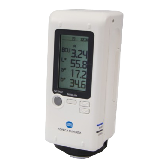
Points to Remember When using the instrument with the supplied PC application, the instrument’s settings can be confi gured, measurement can be performed, and measurement data can be viewed in a list and saved/cleared. Instrument Operation/Display Display (LCD Screen) The screen shows various settings used for measuring as well as measurement results, The LCD screen on the top of the instrument is used to display measurement results and messages, and other information. - Page 20 Points to Remember (Cont.) Icon Displays (Status indicator icons/Measurement setting icons) None Shows that the remaining battery power is suffi cient. 1. 2. 3. 4. 5. 1. Battery status/USB power display Shows that the remaining battery level is low. Replace the batteries. 2.
-
Page 21: Instrument Info Display
Instrument Info Display Checking CR-10 Plus Checking Instrument Firmware Version Information The information will be displayed at the top of the <MENU> screen. Ex.: Ver.1.00.0000 Ver.1.00.0000 MENU Back Browse Data Language Mask Setting Auto Off Preset Date/Time USB Connec. TARGET... -
Page 22: Chapter 2 Measurement
Chapter 2 Chapter 2 Measurement CAUTION Verify that the USB cable is CAUTION To ensure correct measurement, take connected or that there is suffi cient care to prevent the sample from battery power remaining before slipping away from the sample performing measurement. -
Page 23: Flow Of Measurement
Flow of Measurement ■ Basic operation ■ Advanced operations Perform items marked with (*) using the PC application. Turning the Power ON (Page E-16) Select display language (Page E-33) * As necessary, such as when the power is fi rst turned ON (Page E-17) Exchange target mask Mask setting (Page E-15) -
Page 24: Part 1. Measurement (Basic)
Part 1. Measurement (Basic) -
Page 25: Target Color Setting (Target Measurement)
Target Color Setting (Target Measurement) The target becomes the reference color for measuring how different another color with measurement data is. Before measuring a sample (object to be measured), perform target measurement to set the target color. Memo • Target colors will be shared between each color mode. •... -
Page 26: Measurement (Sample Measurement)
Measurement (Sample Measurement) This function measures a sample (object to be measured) against a target (target color) Notes Measurement results that exceed the range of guaranteed performance will and displays the color difference. It is necessary to obtain target information before be displayed as in the following diagram. -
Page 27: Part 2. Measurement (Advanced)
Part 2. Measurement (Advanced) Memo Some settings can be confi gured on the instrument when turned ON in the settings of the supplied PC application. For more on these settings, read “Instrument Menu Customization” regarding the environment settings for the instrument (Page E-59). -
Page 28: Various Settings/Instrument Settings
Various Settings/Instrument Settings Confi gure the tolerance, and confi rm. Instrument Menu Customization Tol. Judg. (Pre-set Tol.) MENU/OK — Confi gure as necessary — Press to switch the values to ascending order, and press to switch to descending order. With this instrument, a tolerance width can be pre-confi... -
Page 29: Avg. Meas
Various Settings/Instrument Settings (Cont.) Move the selection frame to “** times” and Instrument Menu Customization 10:00 Avg. Meas. confi rm. MENU MENU/OK — Confi gure as necessary — Back and will be displayed above and below the Sets the number of measurements to perform when averaging measurements. -
Page 30: Avg. Meas
Various Settings/Instrument Settings (Cont.) Avg. Meas. After the number of averaging measurements 10:00 is reached, the buzzer will emit a “beep” and 01/05 This section explains how to perform measurement when average measurement has the color difference average will be displayed. been confi... -
Page 31: Preset
Various Settings/Instrument Settings (Cont.) Instrument Menu Customization Preset — Confi gure as necessary — Go back to the measurement screen. 10:00 Measurement conditions can be confi gured collectively by using the PC application to MENU/OK Set. A display confi gure the measurement conditions (average measurement count, tolerance, color Target space, etc.) beforehand and then saving the conditions to the instrument to be called later. -
Page 32: Mask Setting
Various Settings/Instrument Settings (Cont.) Instrument Menu Customization Mask Setting — Confi gure as necessary — Go back to the measurement screen. 10:00 “Auto Detect” is set under Mask Setting on the instrument when shipped from the factory. MENU/OK MAV display When automatic detection is not possible, confi... -
Page 33: Various Settings/Other Settings
Various Settings/Other Settings Language — Confi gure as necessary — It is possible to change the display language Go to the <MENU> screen. Ver.1.00.0000 MENU/OK MENU Back Browse Data Language Avg. Meas. Tol. Judg. Select “Language” and confi rm. Mask Setting MENU/OK Auto Off ... -
Page 34: Auto Off
Various Settings/Other Settings (Cont.) Instrument Menu Customization Auto Off — Confi gure as necessary — The instrument includes an Auto Off function. When using battery power, this function Go back to the measurement screen. automatically turns the power OFF if the operation keys are not operated within the MENU/OK specifi... -
Page 35: Date And Time Setting
Various Settings/Other Settings (Cont.) Date and Time Setting Save to Instrument — Confi gure as necessary — Memo • This setting is only displayed and usable when the “Save to Instrument” Go back to the <MENU> screen. setting for saved data is turned ON using the PC application. MENU/OK •... -
Page 36: Measurement Data Operations
Measurement Data Operations Browse Data Save to Instrument It is possible to view the details of data saved to the instrument. Go back to the <MENU> screen. Memo • This setting is only displayed and usable when the “Save to Instrument” MENU/OK setting for saved data is turned ON using the PC application and data is saved. -
Page 37: Chapter 3 Pc Application
Chapter 3 Chapter 3 PC Application Notes on Use • This software is application software for use with Windows 10 or Windows 11. Please note that this software does not include any OS. • One of the above OS must be installed on the PC in order to install this software. •... -
Page 38: Connecting To A Pc
Color Reader • Firmly push in the USB cable connector that matches the shape of the CR-10 Plus (Commercially available) port (connection terminal) until it can go in no further. • With Windows 10 or Windows 11, if the instrument can only be operated using USB Feed, set “USB selective suspend setting”... -
Page 39: When First Connecting To The Pc
Connecting to a PC (Cont.) When First Connecting to the PC ❹ Move the selection frame to “PC” using either 10:00 MENU/OK MENU , and then press Notes • To use a PC application with the instrument connected to a PC, the Back dedicated USB driver must be installed. - Page 40 Connecting to a PC (Cont.) ❷ Updating the drive manually After installing, click “Close”. If the connected instrument is not displayed under [Ports (COM & LPT)] and is ❷-4 Confi rm the COM port number from instead displayed under [Other Devices] as “! Unknown Device”, the USB driver will step ❶, and then navigate to [Device need to be installed manually.
-
Page 41: Launching The Pc Application
Connecting to a PC (Cont.) Launching the PC Application ❸ Double-click the “CRX_APP.exe" fi le copied to the PC’s hard drive to launch the PC application. Memo The PC application cannot be run when logged in to the PC under a “Guest” account. -
Page 42: Points To Remember
Points to Remember PC Application Settings Using the supplied PC application, the items displayed on the instrument’s menus can be customized. Change the settings as required. Settings for the instrument can be confi gured through the “Setting” screen on the PC application. The items that appear on the instrument’s settings menu are as follows. -
Page 43: Using The Numeric Pad
Points to Remember (Cont.) Using the numeric pad Cancel key If the input range is exceeded, an alert will be Clears the input value. displayed and the input data will be cleared. Back key The last input value will be deleted. Clear key Clears the input value. -
Page 44: Pc Application Operation Screen
Points to Remember (Cont.) PC Application Operation Screen The supplied PC application is confi gured with three operation panels: “Setting”, “Measure”, and “Data”. The following describes the functions available on each screen. Instrument Info Display Memo The settings confi gured using the PC application are refl ected on the instrument. Displays the instrument’s serial number and fi... - Page 45 Points to Remember (Cont.) [Measure] Tab Measurement can be performed when the instrument settings are met and the PC application is running. Memo The settings confi gured on the PC application will also be applied when measuring remotely from the PC application. When performing remote measurement from the PC application, the “Meas.
- Page 46 Points to Remember (Cont.) [Data] Tab Functions related to measurement data saved to the instrument are available in the [Data] tab. This tab allows target and sample data saved in the instrument to be imported and displayed as a list before being saved to the PC. Measurement data saved in instrument Read...
-
Page 47: Instrument Info Display
Instrument Info Display Checking CR-10 Plus Information The instrument information and version of an instrument connected to the PC can be checked on the PC application screen. Serial No. Firmware version of the connected instrument... -
Page 48: Instrument Settings
Instrument Settings Instrument Menu Customization Mask Setting — Confi gure as necessary — “Auto Detect” is set under Mask Setting on the instrument when shipped from the factory. If for some reason automatic detection is not possible, confi gure the settings appropriately for the target mask attached. -
Page 49: Avg. Meas
Instrument Settings (Cont.) Instrument Menu Customization Avg. Meas. — Confi gure as necessary — Sets the number of measurements to perform when averaging measurements. After setting the number of averaging measurements and pressing the measuring button that many times, an average value from the obtained data will be displayed as the measurement. -
Page 50: Tol. Setting
Instrument Settings (Cont.) Instrument Menu Customization Tol. Setting — Confi gure as necessary — With this instrument, tolerances can be pre-confi gured and saved. Go to the “Setting” screen or the “Measure” screen. Select “None” in the “Preset” settings area. ●... -
Page 51: Preset Settings Tab (Set. A-Set. C)
Instrument Settings (Cont.) Preset Settings Tab (Set. A–Set. C) 1 3 4, 5 2, 4 — Confi gure as necessary — The measurement conditions (average measurement count, tolerance, and color space) can be pre-confi gured in up to three ways using the instrument. Also, if Setting A, B, or C is saved to the measurement conditions, the measurement conditions can be switched to show the measurement results. - Page 52 Instrument Settings (Cont.) Confi gure Tol. The preset function allows tolerances other than ΔE to be set. Click the check box to the left of the item to confi gure. (Here, the color space is set to L*a*b*, and the tolerances for ΔL* and Δa* are confi...
-
Page 53: Environment Settings (Changing Instrument Settings)
Environment Settings (Changing Instrument Settings) Save Meas. Data Measured data can be saved to the instrument. Go to the “Setting” screen. Click the check box to the left of “Save to Instrument”. Up to 1000 measurement data entries can be saved. In addition, this application can be used to display data saved in the instrument in a list and to save the data to the PC. -
Page 54: Language
Environment Settings (Changing Instrument Settings) (Cont.) Language — Confi gure as necessary — It is possible to change the display language Go to the “Setting” screen. In the “Environment” settings area, under “Language”, select the desired language Click ○. The radial will change to , and the language will be selected. Clicking this will cause the display language for the PC application and the instrument to change simultaneously. -
Page 55: Auto Off
Environment Settings (Changing Instrument Settings) (Cont.) Auto Off — Confi gure as necessary — The instrument includes an Auto Off function. When the instrument is using battery power, this function automatically turns the power OFF if the operation keys are not operated within the specifi... -
Page 56: Date/Time Setting
Environment Settings (Changing Instrument Settings) (Cont.) Date/Time Setting — Confi gure as necessary — Memo This setting is only displayed and usable when the “Save to Instrument” setting for saved data is turned ON using the PC application. When the PC application is running, the date and time is obtained from the instrument and displayed on the PC application screen. -
Page 57: Settings Only Configurable From The Pc Application
Environment Settings (Changing Instrument Settings) (Cont.) * Settings Only Configurable from the PC Application — Confi gure as necessary — The buzzer is set to “ON” when the instrument is shipped from the factory. This buzzer sound can be switched ON/OFF. Change the settings as required. Turning the buzzer ON/OFF The buzzer sound on the instrument can be switched ON/OFF. - Page 58 Environment Settings (Changing Instrument Settings) (Cont.) * Settings Only Confi gurable from the PC Application — Confi gure as necessary — LED (READY Lamp, STATUS Lamp) Display The display settings for the LED lamps on the instrument can be changed. When the LED display is set to ON (either set to “On”...
- Page 59 Environment Settings (Changing Instrument Settings) (Cont.) * Settings Only Confi gurable from the PC Application — Confi gure as necessary — Instrument Menu Customization This function enables certain settings to be confi gured on the instrument. Items switched to ON will be confi gurable on the instrument. The items that can be confi...
-
Page 60: Pc Application (Measurement)
PC Application (Measurement) <Remote Measurement and Trigger Measurement When the PC application for the instrument is running, measurement can be done remotely or by using a trigger. ■ Remote Measurement Click the measuring button on the PC application to measure remotely. ■... -
Page 61: Target Color Setting (Target Measurement)
Target Color Setting (Target Measurement) Target Measurement The target becomes the reference color for measuring how different another color with measurement data is. Before measuring a sample, perform target measurement to set the target color. Memo When the buzzer is set to ON, the buzzer will emit a sound when measuring. The following explanations assume that the buzzer sound has been set to ON. -
Page 62: Target Measurement (Undo)
Target Color Setting (Target Measurement) (Cont.) Target Measurement (Undo) The following procedure explains how to measure the target again and re-obtain the target information. The obtained target data is then written to the instrument. With the target information displayed, click “Clear Target”. The target information will be cleared. -
Page 63: Calling The Most Recent Target
Target Color Setting (Target Measurement) (Cont.) Calling the Most Recent Target If data has already been obtained, the most recently obtained data will be stored. The following procedure explains how to recall data from the previous session. Click “Call”. The most recently obtained target data will be displayed. -
Page 64: Writing Target Information To The Instrument
Target Color Setting (Target Measurement) (Cont.) Writing Target Information to the Instrument This function writes target data obtained through remote measurement from the PC application to instrument. With the target information displayed on the PC application, click “Write to Instrument”. Click “Yes”... -
Page 65: Measurement (Sample Measurement)
Measurement (Sample Measurement) Sample Measurement This function measures a sample (object to be measured) against a target (target color) and displays the color difference. It is necessary to obtain target information before sample measurement. Display the target information to be used on the screen. Set the sample surface aperture on the sample to measure again. -
Page 66: Avg. Meas
Measurement (Sample Measurement) (Cont.) Avg. Meas. This section explains how to perform measurement when average measurement has been confi gured. The average count and the number of measurements will be displayed beside the measuring button. With the target to be used displayed on the instrument’s LCD screen, set the instrument’s sample surface aperture on the sample to measure. -
Page 67: Save Meas. Data
Save Meas. Data Save Meas. Data Data measured using remote measurement or trigger measurement through the PC application can be saved to the PC. Notes For this setting, make sure to copy the PC application to the PC’s hard drive before running the application. Under “Save Meas. -
Page 68: Measurement Result Display
Measurement Result Display Importing Measurement Data All data saved in the instrument is referenced and displayed in a list. Memo This operation is only possible when the “Save to Instrument” setting is turned ON in the PC application and there is saved data in the instrument. Notes Data acquisition may take longer when the number of data entries is large. -
Page 69: Measurement Data Operations
Measurement Data Operations Save to PC (Obtain Measurement Data Saved in Instrument) Import data saved in the instrument to a specifi ed destination. Notes For this setting, make sure to copy the PC application to the PC’s hard drive before running the application. Click “Save to PC”. -
Page 70: Clear Inst. Data
Measurement Data Operations (Cont.) Clear Inst. Data Delete all data saved in the instrument. Performing this operation will clear the list. Memo Data cannot be cleared using the instrument itself. Click “Clear Inst. Data”. Click “Yes”. The data will be cleared. Click “OK”. -
Page 71: Copy To Clipboard
Measurement Data Operations (Cont.) Copy to Clipboard This function copies the data displayed in the sample data display area. Click “Copy to Clipboard”. Memo All sample data related to the target data selected in the Target List will be copied. Copied data can be pasted into Excel and other applications. -
Page 72: Chapter 4 Other Functions
Chapter 4 Chapter 4 Other Functions... -
Page 73: Connecting A Printer
The instrument can also be connected to a printer, and the sample data or target data displayed on the instrument’s LCD screen can be printed. For information on connectable printers, contact a KONICA MINOLTA-authorized service facility. Memo • Only text can be output to the printer. -
Page 74: Printing Measurement Data
Connecting a Printer (Cont.) Printing Measurement Data Disconnecting from the Printer ❶ This function can be used to print measurement data. Disconnect the printer from the instrument. Ver.1.00.0000 MENU/OK The instrument must be connected to the printer in advance. See page E-73 “Connecting MENU ❷... -
Page 75: Chapter 5 Troubleshooting
Chapter 5 Chapter 5 Troubleshooting... -
Page 76: Memory Errors
Memory Errors Performing Recovery The following may occur if the cable connecting the instrument to the PC is disconnected. • It may become impossible to save fi les to the instrument. • Files saved on the instrument may become unreadable. Data recovery can be performed if such memory errors occur. - Page 77 Memory Errors (Cont.) Check whether the USB cable is connected or if there is suffi cient <Memory recovery failed> battery power remaining. Click “OK”. 10:00 Notes If this message is displayed, contact a KONICA Memory MINOLTA-authorized service facility. recovery Select “Yes” and confi rm. failed.
-
Page 78: Error Messages
The messages below may be displayed when using the instrument. When one of these messages is displayed, please take the action indicated below. After performing the action, if the instrument does not return to normal, contact a KONICA MINOLTA-authorized service facility. -
Page 79: Checking For Malfunction
In the event that of a malfunction with the instrument, carry out the following measures. If the instrument does not return to normal, try turning the power OFF. If this does not work, contact the nearest KONICA MINOLTA-authorized service facility. -
Page 80: Chapter 6 Appendix
Chapter 6 Chapter 6 Appendix... -
Page 81: Dimensions
Dimensions With target mask (MAV) installed (Unit: mm) Tripod mount screw Measurement target surface ø40 (depth: 6) 50.2 ø11 Center of light-receiving area... -
Page 82: Main Specifi Cations
Main Specifi cations Model Color Reader CR-10 Plus 8°: di (8° illumination angle/diffuse viewing: specular component included) Illumination/viewing system (conforms to DIN 5033 Teil 7, JIS Z 8722 condition d, ISO 7724/1, CIE No. 15, ASTM E 1164) Detector Silicon photocells (6 pcs.) - Page 83 < CAUTION > KONICA MINOLTA WILL NOT BE LIABLE FOR ANY DAMAGES RESULTING FROM THE MISUSE, MISHANDLING, UNAUTHORIZED MODIFICATION, ETC. OF THIS PRODUCT, OR FOR ANY INDIRECT OR INCIDENTAL DAMAGES (INCLUDING BUT NOT LIMITED TO LOSS OF BUSINESS PROFITS, INTERRUPTION OF BUSINESS, ETC.) DUE TO THE USE OF OR INABILITY TO USE THIS PRODUCT.
- Page 84 ©2015-2022 9222-A80F-13 CCMBDA...
Need help?
Do you have a question about the CR-10 Plus and is the answer not in the manual?
Questions and answers