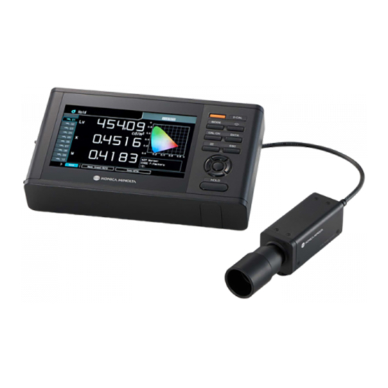
Konica Minolta CA-410 Instruction Manual
Display color analyzer, probe + data processor
Hide thumbs
Also See for CA-410:
- Instruction manual (82 pages) ,
- Instruction manual (128 pages) ,
- Instruction manual (79 pages)

Related Manuals for Konica Minolta CA-410


Summary of Contents for Konica Minolta CA-410
- Page 1 Display Color Analyzer CA-410 Data Processor Probe + CA-DP40 Instruction Manual Please read before using the instrument.
- Page 2 This symbol indicates class II protection against electric shock. Notes on this Manual • Copying or reproduction of all or part of the contents of this manual without the permission of KONICA MINOLTA is strictly prohibited. • The contents of this manual are subject to change without prior notice.
-
Page 3: Safety Precautions
(50/60 Hz) AC outlet of the rated voltage and frequency. If an AC adapter other than those specified by KONICA MINOLTA is used, or if the adapter is connected to an unsupported voltage, it may result in damage to the instrument or AC adapter, fire, or electric shock. - Page 4 Safety Precautions Do not touch the battery with wet hands. Doing so may result in electric shock or a malfunction. Use Data Processor CA-DP40 to charge the lithium-ion battery. If charging conditions or a charger different from that specified is used for charging, the battery may leak, overheat, or catch fire. Do not use, charge, or store the lithium-ion battery in a high-temperature environment.
-
Page 5: Introduction
Introduction The CA-410 series is an instrument designed to measure the color, luminance, and flicker of various color displays. Please read this manual carefully before using the instrument. Packing materials of the product Be sure to keep all packing materials used for shipping the instrument (cardboard box, cushioning material, plastic bags, etc.). - Page 6 • Do not attempt to replace the data processor’s built-in backup battery. The battery should only be replaced by KONICA MINOLTA. To replace the backup battery, please contact a KONICA MINOLTA-authorized service facility. • Periodic backup of important data and settings to another storage medium is recommended.
- Page 7 Never use organic solvents (such as benzene or thinner) or other chemicals for cleaning. • If you are unable to remove dirt from the instrument or if the instrument becomes scratched, contact a KONICA MINOLTA- authorized service facility.
-
Page 8: Table Of Contents
Table of Contents Safety Precautions ........... 1 Introduction ............ 3 CA-DP40 ......39 Data processor Configuration of the CA-410 Series ....8 Data Processor CA-DP40 ........ 40 1. Configuration ..........8 1. About the Data Processor ......40 2. System Diagram ..........9 2. - Page 9 Initializing the Settings ........ 120 Calibration/Settings ......80 Outline of the Calibration/Settings Section..81 Communication .......121 1. Measurement using Konica Minolta’s Calibration Standard ........81 RS-232C Connection ........122 2. Measurement using user calibration ....81 1. Connection to a PC or PLC via RS-232C ..122 Calibration.............
-
Page 10: Configuration Of The Ca-410 Series
Configuration of the CA-410 Series 1. Configuration The CA-410 series consists of the following three systems: zProbes „ Sensor units for measuring displays. Can be connected to a PC to perform measurement (using PC software). Can be connected to a data processor to perform measurement. -
Page 11: System Diagram
2. System Diagram Data Processor standard accessory Probe standard accessory Optional accessory [Probe] Standard Probe High Sensitivity Probe CA-P427 CA-VP427 (miniDIN) (BNC) BNC Conversion Cable IF-A35 CA-P410 CA-VP410 (miniDIN) (D-sub) (Power Cable) (BNC) Conversion Cable IF-A29 Miniature Probe CA-MP410 RS-232C cable (Commercially available) USB Cable for * A lens hood and lens cap are... -
Page 13: Probe Guide
Probe Guide Probes ..................12 1. About Probes ................12 2. Probe Lineup (All Probes are Provided with Lens Caps) ....13 3. Standard Accessories ..............13 4. Optional Accessories ..............14 5. Description of Each Part of Probes ..........14 6. -
Page 14: Probes
Probes 1. About Probes A CA-410 series probe can be used to measure the luminance, chromaticity, and flicker values of displays. A probe can be controlled in the following three ways: • You can connect a probe to a PC and control it from PC software to perform measurement. By using the standard software, PC Software CA-S40 For Color Analyzers, you can select one of the probes connected to a PC via USB and control it to perform measurement. -
Page 15: Probe Lineup
2. Probe Lineup (All Probes are Provided with Lens Caps) Eight types of probes are available according to your application: Model Name Description Dimensions CA-P427 Ø27 Probe Probe with a measurement area of 27 mm P. 16 CA-P427H Ø27 Probe for high luminance High-luminance probe with a measurement area of 27 mm P. -
Page 16: Optional Accessories
Probes 4. Optional Accessories zConversion Cable IF-A29 „ Connects a probe to a PC or PLC (sequencer) via RS-232C and inputs synchronization signals to the probe. How to connect: Refer to page 22. zBNC Conversion Cable IF-A35 „ Inputs synchronization signals to the probe. How to connect: Refer to page 22. - Page 17 (4) Screw holes There are two types of screws for securing a probe: Tripod mount screw: Used for mounting the probe on a tripod. The depth is 6 mm. ISO screw: Used for securing the probe to jigs. Use an ISO 5 mm screw and the depth is 6 mm. • The distance from each screw to the end of the optical column is the same as that for a CA-310 series probe.
-
Page 18: Probe Dimensions
Probes 6. Probe Dimensions CA-P427 Ø27 Probe Probe with a measurement area of 27 mm CA-P427H Ø27 Probe for High Luminance High-luminance probe with a measurement area of 27 mm (unit: mm) ISO 5 mm screw (depth: 6 mm) ISO 5 mm screw (depth: 6 mm) Tripod mount screw (depth: 6 mm) Tripod mount screw... - Page 19 CA-P410 Ø10 Probe Probe with a measurement area of 10 mm CA-P410H Ø10 Probe for High Luminance High-luminance probe with a measurement area of 10 mm (unit: mm) ISO 5 mm screw (depth: 6 mm) ISO 5 mm screw (depth: 6 mm) Tripod mount screw (depth: 6 mm) Tripod mount screw...
- Page 20 Probes CA-VP427 Ø27 High Sensitivity Probe High-sensitivity probe with a measurement area of 27 mm (unit: mm) A Tripod mount screw (depth: 6 mm) ISO 5 mm screw (depth: 6 mm) ISO 5 mm screw (depth: 6 mm) When a light- shielding cylinder is mounted Viewed from A...
- Page 21 CA-VP410 Ø10 High Sensitivity Probe High-sensitivity probe with a measurement area of 10 mm (unit: mm) A Tripod mount screw (depth: 6 mm) ISO 5 mm screw (depth: 6 mm) ISO 5 mm screw (depth: 6 mm) When a light- shielding cylinder is mounted Viewed from A...
- Page 22 Probes CA-MP410 Ø10 Mini Probe Compact probe with a measurement area of 10 mm CA-MP410H Ø10 Mini Probe for High Luminance Compact high-luminance probe with a measurement area of 10 mm (unit: mm) 4 x ISO 3 mm screw (depth: 5.5 mm) ISO 3 mm screw (depth: 5 mm) ISO 5 mm screw (depth: 6 mm) ISO 5 mm screw (depth: 6 mm)
-
Page 23: How To Set A Probe
7. How to Set a Probe Secure the display. L = 30 mm Display surface of the display (when a light-shielding cylinder is not used) Secure the probe in a way to place its end 30 mm * away from the display surface. Be sure to set it perpendicular to the display. - Page 24 Probes • For RS-232C connection with a PC or PLC, connect the mini DIN plug of an optional conversion cable IF-A29 to the RS-232C connector of the probe, and the D-sub plug to the RS-232C connector of the PC or PLC via a cross cable. The baud rate of the probe is set to 38,400 bps.
-
Page 25: About Zero Calibration
For connection with a CA-DP40 data processor, you can use a mini DIN cable or a USB cable. • For RS-232C connection, connect the mini DIN plug of the RS mini DIN cable IF-A30 (or IF-A31 or IF-A32) for the data processor to the RS-232C connector of the probe and the probe RS-232C connector of the CA-DP40 data processor. -
Page 26: Measurement Functions Of Probes
Measurement Functions of Probes 1. Measurement Speeds A probe has the following four modes (measurement speeds), which are available according to the purpose. A probe outputs every measured value and a PC or data processor connected to it can retrieve all of them through communication. -
Page 27: Measurement Synchronization Modes
2. Measurement Synchronization Modes Measurement synchronization modes are designed to select a measurement time (integration time) according to the vertical scanning frequency of a display. A probe has the following six types of measurement synchronization modes. Select a mode suitable for the type of the display to be measured. Measurement Display's vertical Measurement time... - Page 28 Measurement Functions of Probes Relationship between measurement speed and measurement synchronization mode The measurement time (integration time) is determined by the selected measurement synchronization mode. Also, the measurement speed (number of measurements/outputs possible per second) is determined by the measurement synchronization mode and the following conditions: • Luminance of the display to be measured • Measurement mode...
-
Page 29: Measurement Modes
3. Measurement Modes A probe has the following measurement modes: Measurement mode Description of mode xyLv mode Mode for displaying and outputting chromaticity coordinates x, y and luminance Lv TduvLv mode Mode for displaying and outputting correlated color temperature T, color difference from blackbody locus duv, and luminance Lv u'v'Lv mode Mode for displaying and outputting u'v' chromaticity diagram coordinates (CIE1976 UCS... -
Page 30: User Memory
(1) Correction coefficient for user calibration (2) Target (3) ID CH00 is a channel for calibration in accordance with the Konica Minolta calibration standard. It can only be used for setting targets or IDs. Users can use CH01 to CH99 for calibration or saving targets. -
Page 31: About User Calibration
(x, y, Lv) to the instrument. Afterward, the value corrected with the specified correction coefficients will be displayed/output for every measurement. • Two types of user calibration can be performed for a CA-410 series probe: single-point calibration and RGB+W matrix calibration. -
Page 32: Specifications Of Each Probe
Specifications of Each Probe Specifications of Each Probe (1) CA-P427 CA-P427H Measurement area Ø27 mm Ø27 mm Acceptance angle ±2.5° ±2.5° Accuracy guaranteed measurement distance 30±10 mm 30±10 mm Display range Luminance 0.0001 to 5000 cd/m 0.0001 to 30000 cd/m Chromaticity Displayed in 4 digits Displayed in 4 digits... - Page 33 0 to 45°C, relative humidity 85% or less (at 35°C) with no condensation Measured with Konica Minolta’s specified PC and probe connected directly, using the supplied measurement software. *1: Measured under Konica Minolta's standard light source (6,500 K). *2: The luminance for monochrome is measured when reading of luminance for white is 100 cd/m *3: Temperature 23°C/±2°C, relative humidity 40%±10%...
- Page 34 Specifications of Each Probe (2) CA-P410 CA-P410H Measurement area Ø10 mm Ø10 mm Acceptance angle ±5° ±5° Accuracy guaranteed measurement distance 30±5 mm 30±5 mm Display range Luminance 0.0001 to 5000 cd/m 0.0001 to 30000 cd/m Chromaticity Displayed in 4 digits Displayed in 4 digits Luminance Accuracy guaranteed luminance range...
- Page 35 0 to 45°C, relative humidity 85% or less (at 35°C) with no condensation Measured with Konica Minolta’s specified PC and probe connected directly, using the supplied measurement software. *1: Measured under Konica Minolta's standard light source (6,500 K). *2: The luminance for monochrome is measured when reading of luminance for white is 100 cd/m *3: Temperature 23°C/±2°C, relative humidity 40%±10%...
- Page 36 Specifications of Each Probe (3) CA-MP410 CA-MP410H Measurement area Ø10 mm Ø10 mm Acceptance angle ±5° ±5° Accuracy guaranteed measurement distance 10±5 mm 10±5 mm Display range Luminance 0.0001 to 5000 cd/m 0.0001 to 30000 cd/m Chromaticity Displayed in 4 digits Displayed in 4 digits Luminance Accuracy guaranteed luminance range...
- Page 37 0 to 45°C, relative humidity 85% or less (at 35°C) with no condensation Measured with Konica Minolta’s specified PC and probe connected directly, using the supplied measurement software. *1: Measured under Konica Minolta's standard light source (6,500 K). *2: The luminance for monochrome is measured when reading of luminance for white is 100 cd/m *3: Temperature 23°C/±2°C, relative humidity 40%±10%...
- Page 38 Specifications of Each Probe (4) CA-VP427 CA-VP410 Measurement area Ø27 mm Ø10 mm Acceptance angle ±2.5° ±8.5° Accuracy guaranteed measurement distance 30±10 mm 30±5 mm Display range Luminance 0.0001 to 3000 cd/m 0.0001 to 3000 cd/m Chromaticity Displayed in 4 digits Displayed in 4 digits Luminance Accuracy guaranteed luminance range...
- Page 39 0 to 45°C, relative humidity 85% or less (at 35°C) with no condensation Measured with Konica Minolta’s specified PC and probe connected directly, using the supplied measurement software. *1: Measured under Konica Minolta's standard light source (6,500 K). *2: The luminance for monochrome is measured when reading of luminance for white is 100 cd/m *3: Temperature 23°C/±2°C, relative humidity 40%±10%...
-
Page 41: Data Processor
Data processor CA-DP40 Data Processor CA-DP40 ............40 1. About the Data Processor ............40 2. Standard Accessories ..............40 3. Optional Accessories ..............41 Names and Functions of Parts ..........42 Display Screen ................ 44 1. Screen configuration ..............44 2. -
Page 42: Data Processor Ca-Dp40
Data Processor CA-DP40 1. About the Data Processor This data processor is designed to control probes that measure the luminance, chromaticity, and flicker of displays. The processor supports connection to multiple probes (up to 10) to perform measurement simultaneously. The processor can also be connected to a PC and controlled using PC software. 2. -
Page 43: Optional Accessories
3. Optional Accessories zUSB cable for Probe-PC IF-A28 Connects the data processor to a probe via USB. Description in this manual How to connect: Refer to page 59. zUSB cable for DP-PC IF-A34 Connects the data processor to a PC via USB. Description in this manual How to connect: Refer to page 124. -
Page 44: Names And Functions Of Parts
Names and Functions of Parts <Front> (10) (12) (11) (1) [BACKLIGHT] key ���������������� Switches the backlight of the LCD display ON/OFF. (2) [DATA] key �������������������������� On the measurement screen, press this key to switch to the data screen for checking or deleting measurement results and logs. - Page 45 <Top> <Rear> <Left> (11) (12) (13) (14) (10) <Top> (1) POWER switch������������������������������������ Turns ON and OFF the power to the instrument. (P. 63) (2) Probe USB connectors ������������������������ Used to connect probes using USB cables. Up to 10 probes can be connected simultaneously. Keep caps on probe connectors not in use.
-
Page 46: Display Screen
Display Screen 1. Screen configuration There are two types of screens: basic and pop-up. The basic screen has three areas—status display, setting, and data display. 2. Basic screen The screen shown below is the basic screen, which displays the status of the instrument and data. •... - Page 47 • Trigger mode Trigger mode enabled (Trigger mode ON and interval OFF) No display Trigger mode disabled • 0-cal Auto 0-cal Auto ON 0-cal Auto OFF and when the temperature changes No display 0-cal Auto OFF and when the temperature doesn’t change • Key lock Key locked No display...
- Page 48 Display Screen (2) Settings area Contains shortcut key icons for saving and setting measurement data. Shortcut keys in the setting area are not displayed on screens other than the measurement screen (such as the menu screen). The setting area is enabled only in hold mode. (Single-probe measurement screen and multi-probe measurement screen) Measuring Hold Measuring...
- Page 49 (3) Measurement data area Used to display measured data or configure settings by pressing menu keys. There are two types of screens that display values being measured: a screen that displays the values measured by a selected single probe and a screen that displays all values measured by multiple probes. (3)-1.
- Page 50 Display Screen (3)-2. Single-Probe Display Measuring Trigger mode 0-cal AUTO Data display area 160.00 Graph Measured values cd/ ㎡ 0.3127 0.3293 1.0 x Φ10 Mini Normal Probe information CH-01 f:Factory ID: abcdefghij Meas Speed: LTD.AUTO Sync: MANU. (100. 0ms) Save • Selecting the number of a connected port using the [UP/DOWN] keys displays only the data measured by the probe connected to that port.
-
Page 51: Operations On Each Screen
Operations on Each Screen 1. Measurement screen There are two types of screens that display values being measured: a screen that displays the values measured by a selected single probe and a screen that displays all values measured by multiple probes. Single-Probe Display Multi-Probe Display A screen that displays the values measured by a selected... -
Page 52: Zero Calibration Screen
Operations on Each Screen • About displays In normal measurement (continuous measurement) In interval measurement mode mode and trigger mode Measuring • Pressing the [MODE] key to change the color (including space periods • Pressing the [0-Cal] key to perform zero between calibration measurements) -
Page 53: Changing Color Modes
4. Changing color modes Press the [MODE] key to change the color space for the measured values on the screen. * CA-VP427 and CA-VP410 probes cannot measure flicker. * The displayed color mode screens are only those checked in Color Space under Menu - Option. * Color modes cannot be changed in interval measurement mode. -
Page 54: Graph
Operations on Each Screen 5. Graph The following graphs are displayed on the screen for the measurement results of a single probe. When the color mode is Lv,x,y, Lv,Tcp,duv, X,Y,Z, Lv,Tcp,duv, or Lv,λd,Pe • An xy chromaticity diagram is displayed. When the color mode is Lv,u’,v’... -
Page 55: Menu Screen
6. Menu screen Press the [MENU] key to change probe or data processor settings. The menu screen includes areas 1 to 3, and options for the item selected in area 1 are displayed in area 2, and options or settings for the item selected in area 2 are displayed in area 3. • Select an item in area 2 after selecting an item in area 1 using the [UP]/[DOWN] keys and pressing the [RIGHT] or [ENTER] key. -
Page 56: Manual Structure
Interval Alert / JEITA freq resolution Selecting a Probe No. P. 79 Explains how to select the probe whose measured value is to be displayed. To Calibration/Settings section * Go to the Measurement section if performing measurement using Konica Minolta’s calibration standard. - Page 57 This section explains settings that must be configured according to measurement method. The setting method varies according to the measurement method. From the Measurement Preparation section Outline of the Calibration/Settings Section P. 81 Explains measurement method types and settings that must be configured. (Check which settings must be configured.) Before Configuring Each Setting P.
- Page 58 PC will be enabled, and commands from all other means will be ignored. • If the USB cable will be connected and disconnected frequently, please try to use RS-232C for connection. If any problem occurs, contact a Konica Minolta-authorized service facility.
- Page 59 This section explains the following items. Dimensions P.133 Error Messages P. 134 Please read when an error message appears on the LCD display. Main Specifications P. 135...
-
Page 60: Connection
Connection This section explains how to connect a probe, AC power, turn the power ON ( | )/OFF (), and input the vertical synchronization signal. Connections P. 59 Explains how to connect probes and the power cord, and how to input the vertical synchronization signal. -
Page 61: Connections
Connections 1. Connecting a Probe to the Data Processor Before setting the POWER switch to ON, connect a probe to a probe connector. • A probe can be connected with an USB cable or an RS cable. • For RS-232C connection, connect the mini DIN plug of the Probe-DP RS cable IF-A30 (or IF-A31 or IF-A32) supplied with the data processor to the RS-232C connector of the probe and the probe RS-232C connector of the CA-DP40 data processor. -
Page 62: Attaching/Detaching A Battery
Connections 2. Attaching/Detaching a Battery This instrument uses a dedicated lithium-ion battery (CM-A223). CAUTION • Do not use any battery other than the dedicated lithium-ion battery. Doing so may cause the battery to rupture or result in decreased battery life. • Do not touch or short-circuit the terminals in the battery compartment. -
Page 63: Connecting The Ac Adapter
3. Connecting the AC Adapter CAUTION • Be sure to use the supplied AC adapter AC-A312F. • Before connecting or disconnecting the AC adapter jack or plug, make sure that the instrument is turned OFF. • Firmly push the AC adapter power plug completely into the outlet. Operating Procedure Turn the power OFF. -
Page 64: Connecting A Remote Switch
Connections 5. Connecting a Remote Switch Connecting a commercially available remote switch serves the same function as the HOLD key. CAUTION • Before connecting or disconnecting the AC adapter jack or plug, make sure that the instrument is turned OFF. Operating Procedure Turn the power OFF. -
Page 65: Turning The Power On/Off
Turning the Power ON/OFF 1. Turning the Power ON/OFF Before setting the POWER switch to ON, complete the following. When turning the power ON for the first time after purchase, the language selection and date/time setting screens appear. Set the display language and the date/time on these screens. -
Page 66: Instrument Status At Power-On
P. 123 38400 bps Correction coefficient for user P. 83 Konica Minolta’s standard data calibration To Change the Instrument Status at Power-ON (only for (1), (2), (4), and (5)) Change the necessary parameters and press the [ENTER] key for more than five seconds. A beep will sound, followed by a long beep when the settings are saved. -
Page 67: Measurement Preparation
Sync Mode / Meas Speed / Trigger Mode / Interval Meas / Interval Alert / JEITA freq resolution Selecting a Probe No. P. 79 Explains how to select the probe whose measured value is to be displayed. To the Settings section * Go to the Measurement section if performing measurement using Konica Minolta’s calibration standard. -
Page 68: Zero Calibration
Zero calibration Zero calibration performs zero point adjustment while blocking entry of light into the probe’s receptor. A shutter located inside the probe automatically closes to block light during zero calibration of the instrument. Zero calibration must be performed whenever the POWER switch is set to ON ( | ). 1. -
Page 69: How To Check Zero Calibration
If zero calibration can be performed correctly by shielding the light-receptor on the tip of the probe, the light shield built into the probe is faulty. In either case, contact a KONICA MINOLTA-authorized service facility. 2. How to Check Zero Calibration To check whether zero calibration has been performed correctly, block entry of light into the end of the probe using a blackout curtain, etc., so that the receptor is not exposed to light. -
Page 70: Setting The Sync Mode
Setting the Sync Mode [Meas Cond] - [Sync Mode] The Sync Mode is a mode to perform measurement in synchronization with the fluctuation frequency of a light source that fluctuates brightness at a constant cycle, such as the vertical synchronization frequency of a display unit. * Synchronization frequency setting range: 0.50 to 240.00 Hz * Factory setting: UNIV. - Page 71 -1-2 Press the [UP] or [DOWN] key and the MENU Trigger mode 0-cal AUTO [RIGHT]/[LEFT] keys to set a M e a s C o n d S y n c M o d e ○ NTSC U s e r C a l i b M e a s ...
-
Page 72: Setting The Measurement Speed
Setting the Measurement Speed [Meas Cond] - [Meas Speed] Set the speed for measurement. * Selectable measurement speeds: FAST/ SLOW / AUTO / LTD.AUTO * Factory setting: AUTO Operating Procedure While the measurement screen is displayed, press the [MENU] key. The setting screen is displayed on the LCD screen. -
Page 73: Setting The Trigger Mode
Setting the Trigger Mode [Meas Cond] - [Trigger] In trigger mode, measurement is started by an external trigger. A delay time can be set for starting measurement after a trigger. * Factory setting: OFF Operating Procedure While the measurement screen is displayed, press the [MENU] key. - Page 74 Setting the Trigger Mode Press the [UP] or [DOWN] key and the MENU Trigger mode 0-cal AUTO [RIGHT]/[LEFT] keys to set a delay time, M e a s C o n d S y n c M o d e ◉ON[Delay 100.0 ms] U s e r ...
-
Page 75: Setting The Interval Measurement
Setting the Interval Measurement [Meas Cond] - [Interval Meas] The mode can be set to Interval Meas. In this mode, the measurement interval and the number of measurements can be set. * Factory setting: OFF Operating Procedure While the measurement screen is displayed, press the [MENU] key. - Page 76 Setting the Interval Measurement Press the [UP] or [DOWN] key and the Input Error [RIGHT]/[LEFT] keys to set a value, move The input data is incorrect to [Complete], and then press the Input correct value [ENTER] key. * The interval time can be set to between 10 to 3,600 sec and the interval number to between 1 to 9,999.
-
Page 77: Setting The Interval Alert
Setting the Interval Alert [Meas Cond] - [Interval Alert] This setting determines whether an alert is displayed during interval measurement when a measured value differs substantially from the one measured immediately before. Set a judgment threshold for outputting an alert. After a threshold is set, a measured value will be saved together with an alert if the difference between the value and the previous one exceeds the threshold. - Page 78 Setting the Interval Alert Press the [UP] or [DOWN] key and the MENU Trigger mode 0-cal AUTO [RIGHT]/[LEFT] keys to set a threshold, M e a s C o n d S y n c M o d e ◉ ON [ 50 %] U s e r ...
-
Page 79: Jeita Freq Resolution Setting
JEITA Freq Resolution Setting [Meas Cond] - [JEITA freq resolution] Set the frequency resolution for JEITA flicker measurements. The frequency can be set in units of 0.01 Hz, 0.1 Hz, or 1 Hz. * Factory setting: 1 Hz Operating Procedure While the measurement screen is displayed, press the [MENU] key. - Page 80 JEITA Freq Resolution Setting Press the [ESC] key twice. The measurement screen is displayed on the LCD screen. The JEITA freq resolution setting will be kept even if the POWER switch is set to OFF ().
-
Page 81: Selecting A Probe No
Selecting a Probe No. Measurement will be performed simultaneously using all connected probes. Follow the procedure given below to select the probe connector No. (P1 to P10) to which the desired probe is connected. In this example, probes are connected to probe connectors [P1], [P3], and [P5]. How to Select On the measurement screen, press the [UP] or [DOWN] key to display the probe No. -
Page 82: Calibration/Settings
Gives detailed explanations on calibration channels common to each setting and target P. 82 values. When performing When performing measurement using measurement using Konica Minolta’s user calibration calibration standard Setting/Changing the User calibration Target* Gives detailed explanations on user calibration and... -
Page 83: Outline Of The Calibration/Settings Section
Available measurement methods and the settings that must be made are explained below. 1. Measurement using Konica Minolta’s Calibration Standard With this method, measurement is performed using Konica Minolta’s calibration standard without calibration. Even when setting the target value to calibration channel CH00, measurement must be performed as explained below. -
Page 84: Calibration
A CA-410 Series probe has calibration channels from CH00 to CH99 (100 channels in total). CH00 is a channel for measurement in accordance with Konica Minolta’s calibration standard. The channel is preset with coefficients for Konica Minolta calibration, which cannot be changed by the user. -
Page 85: About User Calibration
(4) By inputting edit correction coefficients ........P. 90 User calibration cannot be performed for calibration channel CH00. (CH00 is a calibration channel for performing measurement in accordance with Konica Minolta’s calibration standard.) The user calibration correction coefficients are used in common for each color mode (L x y, L u’v’, L... -
Page 86: Performing User Calibration
Performing User Calibration 1. By Measurement (Single-point calibration) Operating Procedure While the measurement screen is displayed, press the [MENU] key. The setting screen is displayed on the LCD screen. Press the [UP] or [DOWN] key to select MENU Trigger mode 0-cal AUTO [User Calib], and then press the [RIGHT] M e a s ... - Page 87 When the pop-up screen for single-point MENU calibration is displayed, press the User Calib > Single-point calibration Single-point calibration [ENTER] key to perform measurement. Start measurement 01 CH01 When the measured value is displayed, 校正値 Measured Value press the [ENTER] key to hold the value. Lv x y Measured Value Target Value Meas...
-
Page 88: By Measurement (Rgb+W Matrix Calibration)
Performing User Calibration 2. By Measurement (RGB+W matrix calibration) Operating Procedure While the measurement screen is displayed, press the [MENU] key. The setting screen is displayed on the LCD screen. Press the [UP] or [DOWN] key to select MENU Trigger mode 0-cal AUTO [User Calib], and then press the [RIGHT] M e a s ... - Page 89 The screen for selecting a color is MENU displayed. Press the [UP] or [DOWN] key User Calib > RGB+W matrix calibration Select Color to select the color to measure and then 01 CH01 press the [ENTER] key. Calibration Value Measured Value Complete When the pop-up screen for RGB+W MENU matrix calibration is displayed, press the User Calib > RGB+W matrix calibration...
-
Page 90: By Selecting From Saved Data
Performing User Calibration 3. By selecting from saved data Operating Procedure While the measurement screen is displayed, press the [MENU] key. The setting screen is displayed on the LCD screen. Press the [UP] or [DOWN] key to select MENU Trigger mode 0-cal AUTO [User Calib], and then press the [RIGHT] M e a s ... - Page 91 Select saved data. MENU The screen for selecting a probe is displayed. Press User Calib > Select Source Probe the [UP] or [DOWN] key to select the probe with the information to use, and then press the [RIGHT] or [ENTER] key. The screen for selecting a calibration channel is displayed.
-
Page 92: By Inputting Correction Coefficients
Performing User Calibration 4. By inputting correction coefficients Operating Procedure While the measurement screen is displayed, press the [MENU] key. The setting screen is displayed on the LCD screen. Press the [UP] or [DOWN] key to select MENU Trigger mode 0-cal AUTO [User Calib], and then press the [RIGHT] M e a s ... - Page 93 Press the [UP] or [DOWN] key and the MENU [RIGHT]/[LEFT] key to set values, and User Calib > Edit Correction Coef > Select CH Correction Coef then press the [ENTER] key. Edit Value CH00 To confirm by pressing the ENTER button CH01 CH02 in the “Complete” Move to [Complete] on the confirmation CH03 CH04 screen and press the [ENTER] key to CH05 CH06 return to the menu screen.
-
Page 94: Setting An Id
Performing User Calibration 5. Setting an ID Names can be applied to calibration channels. Memo By default, the channel number is set as the name. Operating Procedure While the measurement screen is displayed, press the [MENU] key. The setting screen is displayed on the LCD screen. Press the [UP] or [DOWN] key to select MENU Trigger mode 0-cal AUTO... - Page 95 Press the [ENTER] key to display the MENU pop-up screen for inputting characters. User Calib > Select CH Use the[]/[] or []/[] keys to CH00 CH01 move the cursor to a target character, CH02 CH03 and then press the [ENTER] key. CH04 CH05 • Input up to 10 characters. CH06 • The selected character is displayed in the text CH07...
-
Page 96: Deleting Calibration Data
Deleting Calibration Data Follow the procedure below to delete saved values. Operating Procedure While the measurement screen is displayed, press the [MENU] key. The setting screen is displayed on the LCD screen. Press the [UP] or [DOWN] key to select MENU Trigger mode 0-cal AUTO [User Calib], and then press the [RIGHT]... - Page 97 -1 When selecting [All CH] and pressing the MENU [ENTER] key, a delete confirmation User Calib > Delete Delete User Calibration CH message is displayed. Press the [RIGHT] Delete all user calibration CH? All CH Select CH or [LEFT] key to select [Yes] or [No], and then press the [ENTER] key to confirm the action.
-
Page 98: Setting/Changing The Target
Setting/Changing the Target 1. Target A target is the value used as a reference to determine how much the measured value differs from it. Use one of the following methods to set a target. (1) By measurement and registration (2) By entering values The target is used in common for each measurement mode (Lv x y, Lv u’v’, Lv Tcp duv, X Y Z, and Dominant wavelength). - Page 99 The screen for selecting a calibration MENU channel is displayed. Press the [UP] or Target > Select CH [DOWN] key to select the channel to CH00 CH01 register. This screen allows the current CH02 CH03 data to be checked. CH04 CH05 CH06 CH07 CH08 CH09 Press the [ENTER] key.
-
Page 100: By Entering Values
Setting/Changing the Target 3. By Entering Values Operating Procedure While the measurement screen is displayed, press the [MENU] key. The setting screen is displayed on the LCD screen. Press the [UP] or [DOWN] key to select MENU Trigger mode 0-cal AUTO [Target], and then press the [RIGHT] or M e a s ... - Page 101 Press the [UP] or [DOWN] key and the MENU [RIGHT]/[LEFT] keys to select the value Target > Select CH Target to set, and then press the [ENTER] key. Edit Value CH00 To confirm by pressing the ENTER button CH01 CH02 in the “Complete” CH03 Lv x y 山路を登りながら CH04 160.2 0.3132 ...
-
Page 102: Measurement
Measurement This section explains measuring methods. From the Settings section Measurement Explains measuring methods, how to hold the measured values, how to read them, and P. 101 how to clear them. -
Page 103: Measurement
Settings (P. 106) This is not necessary if the instrument has already been set up or if measurement will be performed using Konica Minolta’s calibration standard. 1. Performing Measurement Operating Procedure Press the [CAL CH] key to select a probe Select User Calb CH and a calibration channel. -
Page 104: Holding The Measured Values
Measurement Notes on Measurement • Because the luminance of the display is unstable for a while immediately after the display has been turned ON, the measured values must be read after they have stabilized. • Static electricity on the display’s screen surface must be removed as much as possible. • Perform zero calibration if the ambient temperature has changed. - Page 105 Out of Measurement Range Refer to P. 134 for information on error messages. The measurement display section will show “−−−−−” in the following cases. Details Countermeasure The brightness of the measurement Lower the brightness of the measurement target. object exceeds the upper limit. Calculating the correlated color Retry the measurement.
-
Page 106: Checking And Deleting Measurement Data
Measurement 4. Checking and Deleting Measurement Data Press the [DATA] key to check or delete measurement data and interval logs. Operating Procedure Press the [DATA] key. DATA Select Item Check Saved Data Delete Saved Data Check Interval Log Delete Interval Log Press the [UP]/[DOWN] key to select a menu, and then press the [ENTER] key. - Page 107 Press the [UP]/[DOWN] key to select measurement data or interval log, and then press the [ENTER] key. DATA Delete Saved Data > Select Data Delete Saved Data ID Delete Saved Data Delete all Saved Data? All Data Select Data DATA Delete Interval Log > Select Log Delete Interval Log ID Delete Interval Log Delete all interval logs? All Logs Select Log...
-
Page 108: Settings
Settings The Settings section explains the settings that can be configured under [ Menu], [ Option], and System]. Setting the Selectable Color Spaces ....107 Selecting the Color Mode......108 Selecting the Absolute Value/Color Difference Display ........... 109 Setting the Display Brightness...... 110 Setting Operation Sounds ...... -
Page 109: Setting The Selectable Color Spaces
Setting the Selectable Color Spaces This instrument allows users to specify the color spaces that can be selected. * Factory setting: All options selected Operating Procedure While the measurement screen is displayed, press the [MENU] key. The setting screen is displayed on the LCD screen. Press the [UP] or [DOWN] key to select MENU Trigger mode 0-cal AUTO... -
Page 110: Selecting The Color Mode
Selecting the Color Mode The following color modes are available. * Factory setting: Lvxy Color Mode LCD screen display Description of mode Lv x y Mode for displaying and outputting luminance Lv and chromaticity coordinates x, y Lv u’ v’ Luminance Lv and u’v’... -
Page 111: Selecting The Absolute Value/Color Difference Display
Selecting the Absolute Value/Color Difference Display Chromaticity measurement results can be displayed either as the absolute value or the difference. * Chromaticity display method: Absolute Value, Difference * Factory setting: Absolute Value Operating Procedure While the measurement screen is displayed, press the [MENU] key. The setting screen is displayed on the LCD screen. -
Page 112: Setting The Display Brightness
Setting the Display Brightness This instrument allows users to set the brightness of the external LCD screen. * Factory setting: 3 (Standard) Operating Procedure While the measurement screen is displayed, press the [MENU] key. The setting screen is displayed on the LCD screen. Press the [UP] or [DOWN] key to select MENU Trigger mode 0-cal AUTO... -
Page 113: Setting Operation Sounds
Setting Operation Sounds This instrument allows users to turn operation sounds ON or OFF. * Factory setting: ON Operating Procedure While the measurement screen is displayed, press the [MENU] key. The setting screen is displayed on the LCD screen. Press the [UP] or [DOWN] key to select MENU Trigger mode 0-cal AUTO [Option], and then press the [RIGHT] or... -
Page 114: Auto 0-Cal Settings
Auto 0-Cal Settings This instrument can be configured to perform zero calibration automatically. When set to [ON], the shutter of the probe automatically closes and Auto 0-cal is performed if the probe temperature has changed 6°C. * Factory setting: OFF Operating Procedure While the measurement screen is displayed, press the [MENU] key. -
Page 115: Save Destination Setting
Save Destination Setting This instrument can be configured to select the destination to save measurement data automatically or manually. * Factory setting: AUTO Operating Procedure While the measurement screen is displayed, press the [MENU] key. The setting screen is displayed on the LCD screen. Press the [UP] or [DOWN] key to select MENU Trigger mode 0-cal AUTO... -
Page 116: Selecting Luminance Units
Selecting Luminance Units [Option] - [Luminance Units] This instrument allows users to select the luminance units to be displayed. * Factory setting: cd/m Operating Procedure While the measurement screen is displayed, press the [MENU] key. The setting screen is displayed on the LCD screen. Press the [UP] or [DOWN] key to select MENU Trigger mode 0-cal AUTO... -
Page 117: Setting The Power Save Mode
Setting the Power Save mode To save battery, this instrument can be set to turn off automatically if no operation or communication is performed for a specified time. The Power Save mode functions even when measuring. * Factory setting: ON Operating Procedure While the measurement screen is displayed, press the [MENU] key. -
Page 118: Setting The Internal Clock
Setting the Internal Clock The instrument contains an internal clock to record the measurement date and time. Set the date and time of this internal clock. Operating Procedure While the measurement screen is displayed, press the [MENU] key. The setting screen is displayed on the LCD screen. Press the [UP] or [DOWN] key to select MENU Trigger mode 0-cal AUTO... -
Page 119: Setting The Date Format
Setting the Date Format The instrument contains an internal clock to record the measurement date and time. Set the display format of this date and time. Operating Procedure While the measurement screen is displayed, press the [MENU] key. The setting screen is displayed on the LCD screen. Press the [UP] or [DOWN] key to select MENU Trigger mode 0-cal AUTO... -
Page 120: Selecting The Display Language
Selecting the Display Language This instrument allows users to select the language displayed on the external LCD screen. Select the language from English, Japanese, Simplified Chinese, Traditional Chinese, and Korean. Operating Procedure While the measurement screen is displayed, press the [MENU] key. The setting screen is displayed on the LCD screen. -
Page 121: Checking The Instrument Information
Checking the Instrument Information Information about the data processor, such as the serial number and firmware version, can be viewed. Operating Procedure While the measurement screen is displayed, press the [MENU] key. The setting screen is displayed on the LCD screen. Press the [UP] or [DOWN] key to select MENU Trigger mode 0-cal AUTO... -
Page 122: Initializing The Settings
Initializing the Settings This function resets the settings back to the factory settings. The initialization does not delete the measured values, target values, and user calibration information stored in the instrument. Operating Procedure While the measurement screen is displayed, press the [MENU] key. The setting screen is displayed on the LCD screen. -
Page 123: Communication
PC will be enabled, and commands from all other means will be ignored. • If the USB cable will be connected and disconnected frequently, please try to use RS-232C for connection. If any problem occurs, contact a Konica Minolta-authorized service facility. -
Page 124: Rs-232C Connection
RS-232C Connection 1. Connection to a PC or PLC via RS-232C Before setting the POWER switch to ON ( | ), connect an RS-232C cable (9-pin D-sub) to the RS-232C connector on the instrument. The RS-232C connector on the instrument is a 9-pin D-sub female connector. Use a cross cable for the connector. Operating Procedure Set the POWER switch to OFF (). -
Page 125: Setting The Rs-232C Baud Rate
2. Setting the RS-232C Baud Rate This instrument allows users to set a baud rate for RS-232C connection. * Factory setting: 38,400 bps Operating Procedure While the measurement screen is displayed, press the [MENU] key. The setting screen is displayed on the LCD screen. Press the [UP] or [DOWN] key to select MENU Trigger mode 0-cal AUTO... -
Page 126: Usb Connection
USB Connection 1. Connection to a PC via USB A USB cable can be connected/disconnected even if the power to the instrument is ON. In the following procedure, however, the power is turned OFF before a cable is connected. Connect the instrument to a PC with the optional USB cable IF-A34 (2 m). Notes • To connect the data processor to a PC, the dedicated USB driver must be installed. -
Page 127: Ethernet Connection
Ethernet Connection 1. Connection to a PC via Ethernet An Ethernet cable can be connected/disconnected even if the power to the instrument is ON. In the following procedure, however, the power is turned OFF before a cable is connected. Use an Ethernet cable to connect the instrument to a PC. Notes • Connect the connector plug firmly in the correct direction. -
Page 128: Setting The Dhcp
Ethernet Connection 2. Setting the DHCP This instrument allows users to turn communication ON/OFF to enable Ethernet connection to a PC and to set the properties (IP address, subnet mask, and default gateway). * Factory setting: OFF Operating Procedure While the measurement screen is displayed, press the [MENU] key. - Page 129 Repeat steps 5 and 6 for the necessary items. To cancel configuration of the setting in the middle of the procedure, press the [ESC] key. Move to [Complete] and press the [ENTER] key. Press the [ESC] key twice. The measurement screen is displayed on the LCD screen.
-
Page 130: Bluetooth Connection
Bluetooth Connection 1. Connecting via Bluetooth Connect the instrument to a PC with Bluetooth communication functionality using the optional Bluetooth module. Memo To connect the instrument to a PC via the Bluetooth function, appropriate preparations for Bluetooth communication must be performed in advance for both the instrument and the printer. ... -
Page 131: Communication Setup
2. Communication Setup Turn ON the Bluetooth function and configure the meter PIN code. Operating Procedure Start the procedure from the measurement screen. Press the [MENU] key and use the [LEFT] MENU Trigger mode 0-cal AUTO or [RIGHT] key to display the Setting M e a s ... - Page 132 Bluetooth Connection Use the [UP] or [DOWN] key to move the MENU Trigger mode 0-cal AUTO cursor to “Meter PIN”, and then press the M e a s C o n d P o w e r S a v e m o d e ON[10 min] U s e r ...
-
Page 133: Pc Connection
4. PC Connection With the PC as a host, a connection to the instrument can be established using Bluetooth communication. Operating Procedure Verify that the instrument power has been turned ON. Verify that the Bluetooth function on the instrument has been turned ON. Also verity that the instrument is not connected to the PC via another connection method. -
Page 134: Explanation
Explanation This section explains the following items. Dimensions P. 133 Error Messages P. 134 Please read when an error message appears on the LCD display. Main Specifications P. 135... -
Page 135: Dimensions
Dimensions (Unit: mm) 87.5 Rear wall-mounting screw M4 (4 locations) -
Page 136: Error Messages
In such cases, turn the power OFF and back ON if possible, and then retry zero calibration. If the problem persists, contact a KONICA MINOLTA- authorized service facility. Memory Error ER31 Reconnect the probe. -
Page 137: Main Specifications
Main Specifications Luminance 0.0001 to 30000 cd/m Chromaticity Displayed in 4 digits Display Range (Contrast) 0.00 to 999.99% Flicker (JEITA) To 2 decimal places Display 7-inch color LCD WVGA x y (∆L ∆x ∆y) u’ v’ (∆L ∆u’ ∆v’) Tcp duv (∆L ∆Tcp duv) Display Items X Y Z (∆X ∆Y ∆Z) - Page 138 < CAUTION > • KONICA MINOLTA WILL NOT BE LIABLE FOR ANY DAMAGES RESULTING FROM THE MISUSE, MISHANDLING, UNAUTHORIZED MODIFICATION, ETC. OF THIS PRODUCT, OR FOR ANY INDIRECT OR INCIDENTAL DAMAGES (INCLUDING BUT NOT LIMITED TO LOSS OF BUSINESS PROFITS, INTERRUPTION OF BUSINESS, ETC.) DUE TO THE USE...
- Page 140 En 9222-AA1J-12 ©2017 KONICA MINOLTA, INC. BIFBDA...
Need help?
Do you have a question about the CA-410 and is the answer not in the manual?
Questions and answers