Table of Contents

Related Manuals for Konica Minolta CL-200A


Summary of Contents for Konica Minolta CL-200A
- Page 1 To buy, sell, rent or trade-in this product please click on the link below: https://www.avionteq.com/Konica-Minolta-CL-200A-Chromameter www.avionteq.com CHROMA METER CL-200A INSTRUCTION MANUAL Please read before using this instrument.
- Page 2 Safety Symbols The following symbols are used in this manual to prevent accidents which may occur as re- sult of incorrect use of the instrument. Denotes a sentence regarding a safety warning or note. Read the sentence carefully to ensure safe and correct use. Denotes a prohibited operation.
-
Page 3: Safety Precautions
CAUTION instrument or other property.) Do not use batteries other than those specified by KONICA MINOLTA. When installing batteries in the instrument, make sure that they are correctly oriented according to the (+) and (-) marks. Also make sure not to mix new and old batteries, or mix batteries of different types. - Page 4 Konica Minolta authorized service facility. ● In cases of malfunction, do not disassemble the CL-200A or attempt to repair it yourself. Contact the nearest Konica Minolta-authorized service facility.
-
Page 5: Table Of Contents
CONTENTS SAFETY PRECAUTIONS ..........................1 Names and Functions of Parts ........................4 ● Basic Operations ● ..........................7 Preparation ..............................8 Installing the Receptor Head ........................8 Removing the Receptor Head ........................ 8 Selecting measuring units ........................8 Attaching the Strap and the Cap ......................9 Attaching the Cap (Without the Strap).................... -
Page 6: Names And Functions Of Parts
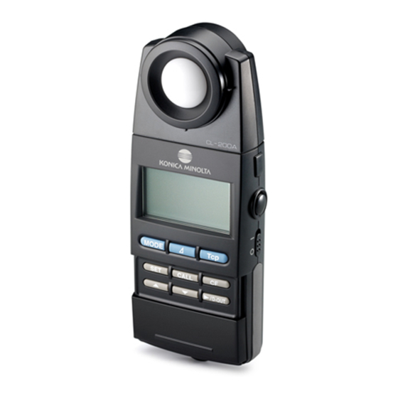
Names and Functions of Parts CL-200A (▲ When the slide cover is open) Receptor Window Display Mode selector keys [MODE] key .......Sets the instrument into color measurement mode, and switches the color coordinates. [∆] key........Sets the instrument into color-difference measurement mode, and switches the color-difference display. - Page 7 Slide cover [SET] key ......• Sets the instrument into SET mode. • Registers a numeric setting into memory. [▲][▼] keys......Use the keys to change a numeric value or move the decimal point. [ /D-OUT] key ....• In modes other than SET mode, use this key to output measurement data to a printer or computer.
-
Page 9: Basic Operations
Basic Operations... -
Page 10: Preparation
Selecting measuring units The Konica Minolta llluminance Meter allows you to take readings in either Lux (lx.) or Foot- candle (fcd) units. 1. Set the power switch to “ ” (OFF), and pull the battery cover while pressing it down slightly. -
Page 11: Attaching The Strap And The Cap
Attaching the Strap and the Cap If you are using the strap, attach the cap to the strap as shown below. 1. Pass the strap through loop of the cap string and then through the strap hook, and then pass one end of the strap through the other. Attaching the Cap (Without the Strap) If you are not using the strap, attach the cap to the main body as follows. -
Page 12: Placing The Chroma Meter Into The Case
3. Pass the string back through the hole in the cap, and tie a knot at the end of the string so that the cap cannot come off. Placing the CHROMA METER into the Case Set the cap onto the receptor window, and slide the CHROMA METER into the case. -
Page 13: Installing The Batteries
Installing the Batteries WARNING Do not allow batteries to come into contact with fire, and do not charge them (unless they are specifically designated as rechargeable), heat them, or take them apart. Any of these actions may cause batteries to overheat or explode, possibly resulting in fire or injury. CAUTION Do not use battery types that are not specified for this instrument. -
Page 14: Turning On The Power
Turning On the Power 1. Set the power switch to the ON position (“|”). ● If the HOLD button is in the RUN position (popped out) when you turn on the power, the CHROMA METER begins taking meas- urements immediately. ●... -
Page 15: Setting The Calibration Mode
Setting the Calibration Mode Calibration Modes The CL-200A CHROMA METER offers two calibration modes: NORM and MULTI. Using the [CF] key allows you to select the calibration mode depending on your application of the instrument. ● The [CF] key should be pressed only while the power switch is on. -
Page 16: Taking Color Measurements
Taking Color Measurements ● When taking measurements, be careful to hold the CHROMA METER so that the recep- tor window is clear of shadows (such as your own shadow) and reflected light. ● Illuminance unit is selectable lx or fcd. (page 8) Measuring Method 1. -
Page 17: Low-Light Alert
Low-Light Alert If the measured illuminance is less than about 5 lx (0.5 fcd), some of the measured values on the display will blink. The blinking display lets you know that the illuminance is low. Specifically, the following values will blink to alert you of this condi- (Values blink to indicate tion: x, y, u’, v’, T, Dominant wavelength/Excitation purity, ∆uv, ∆x, low illuminance) -
Page 18: Taking Color-Difference Measurements
Taking Color-Difference Measurements Use the procedure described below to measure the difference between the sample color and a target color. You can select any of four color-difference displays: (a) ∆Ev ∆x ∆y, (b) ∆Ev ∆u’ ∆v’, (c) ∆Ev ∆u’v’ or (d) ∆X ∆Y ∆Z. Setting the Target Color You can set the target color values in either of two ways. - Page 19 3. Open the slide cover, and press [SET]. ◆ The CHROMA METER enters SET mode, and the dis- play appears as shown in the illustration. ◆ The measurement results that you held at Step 1 above now blink on the display. ●...
- Page 20 2. Press [∆]. ◆ The display shows color-difference parameters. 3. Open the slide cover, and press [SET]. ◆ The CHROMA METER enters SET mode, and waits for you to begin keying in the target values. The display content varies according to whether target values have already been stored, as follows.
- Page 21 To enter a value for Ev, x, y, or z 5. Press [ /D-OUT]. ◆ One or more decimal points begin blinking. ● If a target value is already set for this parameter, the value is displayed. The value’s decimal point blinks. ●...
- Page 22 To enter a value for x, y, u’, or v’ 10. Press [ /D-OUT] as necessary, so that the digit you want to set next starts blinking (becomes active). 11. Press [▲] or [▼] as necessary to change the value of the active digit.
-
Page 23: Taking The Difference Measurement
Taking the Difference Measurement 1. Press and release the HOLD button, so that it pops out (into RUN position). 2. Aim the receptor at the light source you want to measure. ◆ The display shows the measurement results (the differ- ence results). -
Page 24: Measuring The Correlated Color Temperature
Measuring the Correlated Color Temperature 1. Press and release the HOLD button, so that it pops out (into RUN position). 2. Aim the receptor at the light source you want to measure. ◆ The display shows the measurement results. ● Press [Tcp] to display the correlated color temperature. ●... -
Page 25: Using External Power
Switch the instrument off immediately and remove the batteries (or disconnect the adapter from the outlet). Then contact the nearest Konica Minolta-authorized service facility for assistance. CAUTION Read through this manual before powering up this instrument for the first time. -
Page 27: Advanced Operations
Advanced Operations... -
Page 28: Using Correction Factors (Cfs)
This feature is available only when you are using NORM calibration mode (page 13). Using CF Correction The CL-200A CHROMA METER allows you to set correction factors (CFs) that can be ap- plied to your measurement results. You can use this feature to correct for disparities among different CL-200/CL-200As or to adjust calibration arbitrarily as needed. - Page 29 Enter the know values. 1. Open the slide cover, and press [CF]. ◆ The CHROMA METER enters CF mode. 2. Press [SET]. ◆ The display shows the measurement results obtained at step -3 above. If CF values are already set, the display shows the corrected results.
- Page 30 5. Press [▲] or [▼] as necessary to select the number of significant digits. ● If you use the [▲] key, the number of digits cycles as shown in the simplified illustration at left. If you use the [▼] key, the action moves in the reverse direction. (The actual display will show the measurement results held at step -3 above.
- Page 31 11. Repeat steps 10 and 11 as necessary to set values for all digits. ◆ When you have entered values for all digits, the entire value (all digits) will blink. ● You can cancel the entry procedure by pressing [CALL]. 12.
-
Page 32: Applying Cf Correction To Measurements
Applying CF Correction to Measurements 1. Press and release the HOLD button, so that it pops out (into RUN position). ◆ The CHROMA METER begins taking measurements. 2. Open the slide cover, and press [CF]. ● The display now shows the CF-corrected results. Note that the CF indication appears at the top of the display. -
Page 33: Printing Out The Measurement Results
Printing Out The Measurement Results This section explains how to print out the CHROMA METER’s measurement results. In or- der to print, you will need both a compatible printer and the (optional) T-A12 printer cable. Printer Requirements The printer must meet the following requirements. Characters per line :At least 27 Data input... - Page 34 2. Set the CHROMA METER’s power switch to the ON position (“|”), and then turn on the printer. 3. Set the HOLD button to the RUN position (pop the button out), so that the CHROMA METER begins taking measurements. 4. Press [ /D-OUT] to send the results to the printer. ◆...
-
Page 35: Connecting The Chroma Meter To A Computer
USB cable. You can then transfer the measurement data to the computer, and use the com- puter to store and manage the data. If you install KONICA MINOLTA’s standard CL-S10w data management software on your computer, you will also be able to use the computer to view measurement results in real time and to control multi-point measurements. -
Page 36: Separating The Receptor Head From The Body
Separating the Receptor Head from the Body For certain applications you may wish to separate the receptor head and connect it to the body by cable. Two optional adapters—one for the head, and one for the body—make this possible. Required Options ●... -
Page 37: Fixing The Receptor Head In Place
Fixing the Receptor Head in Place When working with the receptor head detached from the main body, you can fix it into posi- tion using either of the following two methods. (For a view of the reference measurement plane, see page 47.) Attach the head to a tripod (using the tripod screw hole on the back of the head). -
Page 38: Multi-Point Measurement
Multi-Point Measurement You can set the CL-200A up to take measurements from multiple points at once. You do this by connecting up multiple receptor heads (each with its own adapter). You can connect up to 30 heads. Extra heads and adapters are available as options. - Page 39 4. Connect the body adapter to one of the head adapters (using the included cable or network cable). 5. Cable the remaining heads together in series. 6. Set an ID number for each head, using the rotary switches on the adapters. ●...
- Page 40 7. Set the power switch to ON (“|”). ◆ The upper right of the screen shows the lowest used ID number. ● Press [▲] or [▼] as necessary to cycle up or down MULTI 0 through the used ID numbers. Confirm that the display cycles through the IDs for all of the connected heads.
-
Page 41: More About Multi-Point Measurement
More about Multi-Point Measurement Setting the Head ID Numbers ● Be sure to set unique ID numbers for all heads. If you set the same number on more than one head, the CHROMA METER will not be able to carry out measurements correctly. About Color-Difference Measurement ●... -
Page 43: Accessories
Accessories... -
Page 44: Included Accessories
Included Accessories Batteries Data Two AA batteries Management Software CL-S10w Strap USB Cable T-A15 Case T-A10... -
Page 45: Optional Accessories
Optional Accessories Adapter Unit for AC-Adapter Main Body T-A20 AC-A308 AC-A311 Adapter Unit for Hard Case CL-A10 Receptor Head T-A21 ● With an extension cable (1m) Printer Cable Hood CL-A11 T-A12 ● Use to suppress t h e i n f l u e n c e of external light when measuring the chromaticity or... -
Page 46: System Configuration Diagram
USB Cable T-A15 (2m) Ex.: Multi-point measurement AA Battery Multi-point measurement requires use of optional (2pcs.)* AC adapter. Optional receptor head CL-200A** Strap Receptor Head **CL-200 receptor head can also be used. For CRT Measurement Hood CL-200A CL-A11 Case T-A10... -
Page 47: Error Messages And Product Specifications
Error Messages and Product Specifications... -
Page 48: Error Messages
Displayed at time of power-on if the body to ON. If the message reappears, contact ErrU and head are not properly connected. the nearest Konica Minolta-authorized service facility. EEPROM error. Set the power switch to OFF and then back ErrE Error in the data stored in the head’s... -
Page 49: Dimension Diagram / Illuminance Reference Plane
Dimension Diagram / Illuminance Reference Plane (Unit: mm) The summit of the receptor window serves as the reference plane, as illustrated below. With receptor head attached to main body Center of receptor Reference plane window φ25 Tripod socket With Adapter Unit attached to receptor head φ4.5 hole 27.5... -
Page 50: Illuminance Measurement Capabilities
JIS (Japan Industrial Standards) has es- tablished a rating system that classifies illuminance meters according to how closely they match this function. The CL-200A CHROMA METER conforms to the “general class AA” classification. (Spectral luminous efficiency) V λ... -
Page 51: Cosine Correction Characteristics
The graph below shows the cosine correction characteristics of the CL-200A CHROMA METER. This instrument confororms to the “general class AA” classification. -
Page 52: Measuring Range For Specimen With High Illuminance
Measuring Range for Specimen with High Illuminance Although the measuring range of this CL-200A is 0.1 to 99,990 lx (chromaticity : 5 lx, 0.5 fcd or above), it may happen that illuminance measurement becomes unable even below 99,990 lx depending on the color of the measured light. -
Page 53: Specifications
±0.0005 (800 lx, Standard Illuminant A measured) Temperature drift E v : ±3% ±1digit of displayed value, xy: ±0.003 (Based on Konica Minolta's standard measurement conditions) Humidity drift E v : ±3% ±1digit of displayed value, xy: ±0.003 (Based on Konica Minolta's standard... -
Page 54: Reference
Reference <CHROMATICITy AND CORRELATED COLOR TEMPERATURE> Chromaticity (xy) Correlated Color Temperature (Tcp) The CIE (Commission Internationale de The concept of is based color temperature l’ Éclairage), an international organization on radiation from a —an ideal black body set up to establish worldwide standards “perfect radiator”... -
Page 55: Dominant Wavelength/Excitation Purity
<DOMINANT WAvELENgTH/ExCITATION PURITy> In the x, y chromaticity diagram shown below, the curve VScSR is the spectrum locus, and point N is the white point . Colors located in the region enclosed by the spectrum locus and the straight lines VN and NR are referred to as spectral colors;... - Page 56 MEMO...
- Page 57 MEMO...
- Page 58 MEMO...
- Page 60 ©2010-2013 KONICA MINOLTA, INC. 9222-A32T-11 BDLEKK Printed in Japan...
Need help?
Do you have a question about the CL-200A and is the answer not in the manual?
Questions and answers