
Related Manuals for Extron electronics CS 26T Plus


Summary of Contents for Extron electronics CS 26T Plus
- Page 1 User Guide Speakers CS 26T Plus and CS 120P CS 1226T Plus SpeedMount Ceiling Speaker System 68-2651-01 Rev. A 09 15...
-
Page 2: Safety Instructions
Safety Instructions Safety Instructions • English Инструкция по технике безопасности • Русский WARNING: This symbol, , when used on the product, is intended to ПРЕДУПРЕЖДЕНИЕ: Данный символ, , если указан alert the user of the presence of uninsulated dangerous voltage within the на... - Page 3 “Extron Safety and Regulatory Compliance ” on the Extron website. Guide Copyright © 2015 Extron Electronics. All rights reserved. Trademarks All trademarks mentioned in this guide are the properties of their respective owners. The following registered trademarks ®...
-
Page 4: Conventions Used In This Guide
Conventions Used in this Guide Notifications The following notifications are used in this guide: WARNING: Potential risk of severe injury or death. Risque potentiel de blessure grave ou de mort. AVERTISSEMENT : ATTENTION: • Risk of property damage. • Risque de dommages matériels. NOTE: A note draws attention to important information. -
Page 5: Table Of Contents
— Division of Labor ......... 18 Installing the CS 26T Plus in a Suspended Ceiling — Division of Labor ......24 Installing the CS 120P in a Hard Ceiling .... 32 CS 26T Plus and CS 120P User Guide • Contents... - Page 6 CS 26T Plus and CS 120P User Guide • Contents...
-
Page 7: Introduction
(for metric systems, the CS 120P end tabs are cut off). • UL 2043 listed — The CS 1226T Plus is UL 2043 listed (only when the CS 26T Plus is used with the CS 120P). -
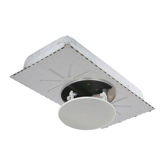
Page 8: Application Example
~ 50 0- 24 HDMI TCP/IP HDMI ® Laptop IP L Extron Blu-ray Desk Microphone IPCP Pro 250 Control Processor Figure 1. Application Diagram of a CS 1226T Plus Installation CS 26T Plus and CS 120P User Guide • Introduction... -
Page 9: Installation
• Using the CS 120P: When used with the CS 120P, the CS 26T Plus can be placed in plenum environments. This is the only configuration that is UL 2043 rated. -
Page 10: Installing The Cs 1226T Plus System - Single Installer
Cut a hole for the CS 26T Plus speaker — Use the provided cutout template to outline the hole to be cut in the ceiling tile as described below. - Page 11 NOTE: A set of fiberglass tile adapters is provided with both the CS 26T Plus and the CS 120P. Only one set is needed to install the CS 26T Plus with the CS 120P kit in a 1-inch (2.5 cm) thick fiberglass tile. The adapter works only with 1-inch (2.5 cm) thick fiberglass tile.
- Page 12 Flexible Conduit Adapter Flexible Conduit Cover Plate Seismic Cable Pass Through Loop Rear of Enclosure Figure 6. Routing the Cables through the Cover Plate Using a Flexible Conduit CS 26T Plus and CS 120P User Guide • Installation...
- Page 13 CS 120P as follows: Cut four strips of adhesive tape (such as duct tape) approximately 4 inches (10.2 cm) long. CS 26T Plus and CS 120P User Guide • Installation...
- Page 14 Route the speaker wires — Route the speaker wires through the ceiling tile hole. Remove the speaker grille — Carefully remove the grille from the front of the CS 26T Plus. NOTE: Grille hooks are provided for grille removal, if needed. CS 26T Plus and CS 120P User Guide • Installation...
- Page 15 Configure the bass reflex port plate — By default, the CS 26T Plus is set up for use with the CS 120P. If not using the CS 120P, set the plate for an open-back installation. With the CS 120P (default configuration): Leave the plate in its default location.
- Page 16 Wiring Multiple Speakers Using Loop-through: A loop-through electrical • connection is made on the crossover board of the CS 26T Plus. Connect the wires to the captive screw connectors of the speakers, as shown in figure 15. Be sure to tighten the screws.
- Page 17 17. Red Wire (+) from Amplifier Amplifier To next speaker(s) Black Wire (-) from Amplifier Test Points Impedance Test Points Figure 17. Impedance Test Points — Loop-through Configuration CS 26T Plus and CS 120P User Guide • Installation...
- Page 18 Attach the speaker wire to the strain relief tie down point using the provided zip tie, see below. Zip Tie Captive Screw Connector Strain Relief Tab Figure 19. Attaching the Speaker Wire to the Strain Relief Point CS 26T Plus and CS 120P User Guide • Installation...
- Page 19 Attach the CS 120P secondary support line to the CS 26T Plus secondary tie off point (if the CS 120P enclosure is not being installed then skip this step) — In the closed back configuration, use the zip tie protruding from the underside of the...
- Page 20 Mount the CS 26T Plus (see figure 22). Insert the CS 26T Plus through the bottom of the hole in the ceiling tile that was cut in step 3 on page 4. Tighten the four screws (clockwise) until the speaker is securely clamped to the ceiling.
- Page 21 (24 mm) and no ceiling tile is installed, use the secondary attachment points as hanger suspension points. • Observe all applicable building codes and local ordinances when installing the speaker. CS 26T Plus and CS 120P User Guide • Installation...
- Page 22 • le niveau d’impédance combinée ne soit pas équivalent à une valeur inférieure à l’impédance minimum de l’amplificateur. 8Ω Adjust the Tap Selector Figure 25. Adjusting the Rotary Tap Selector CS 26T Plus and CS 120P User Guide • Installation...
- Page 23 Six magnets pull the grille securely into place. Speaker Grille Figure 26. Installing the Speaker Grille NOTE: Grille hooks are provided for removal of the grille after installation. CS 26T Plus and CS 120P User Guide • Installation...
-
Page 24: Installing The Cs 120P In A Suspended Ceiling - Division Of Labor
For metric ceilings (600 mm by 600 mm or 600 mm by 1200 mm) cut off the tabs. Tabs (4) Removable Tabs Figure 28. Tabs on the CS 120P CS 26T Plus and CS 120P User Guide • Installation... - Page 25 NOTE: A set of fiberglass tile adapters is provided with both the CS 26T Plus and the CS 120P. Only one set is needed to install the CS 26T Plus with the CS 120P kit in a 1-inch (2.5 cm) thick fiberglass tile. The adapter works only with 1-inch (2.5 cm) thick fiberglass tile.
- Page 26 Flexible Conduit Adapter Flexible Conduit Cover Plate Seismic Cable Pass Through Loop Rear of Enclosure Figure 30. Routing the Cables through the Cover Plate Using a Flexible Conduit CS 26T Plus and CS 120P User Guide • Installation...
- Page 27 Wire the CS 120P — Route the wires through the H-shaped opening in the CS 120P. Be sure to leave sufficient slack. Figure 32. Route the Wires Through the H-shaped Opening CS 26T Plus and CS 120P User Guide • Installation...
- Page 28 2' x 4' (600 mm x 1200 mm) grid mounting. Figure 34. Mounting the CS 120P in a 2' x 4' (600 mm x 1200 mm) Ceiling Grid CS 26T Plus and CS 120P User Guide • Installation...
- Page 29 • Observe all applicable building codes and local ordinances when installing the speaker. Replace the adjacent tile — Reinstall the adjacent tile if one was removed in step 5. CS 26T Plus and CS 120P User Guide • Installation...
-
Page 30: Installing The Cs 26T Plus In A Suspended Ceiling - Division Of Labor
NOTE: A set of fiberglass tile adapters is provided with both the CS 26T Plus and the CS 120P. Only one set is needed to install the CS 26T Plus with the CS 120P kit in a 1-inch (2.5 cm) thick fiberglass tile. The adapter works only with 1-inch (2.5 cm) thick fiberglass tile. - Page 31 In the parallel configuration, all of the speakers downstream of the one being tested continue to function even when it is disconnected. This is especially useful in installations where the system can never be completely down, such as in a hospital setting. CS 26T Plus and CS 120P User Guide • Installation...
- Page 32 Wiring Multiple Speakers Using Loop-through: A loop-through electrical • connection is made on the crossover board of the CS 26T Plus. Connect the wires to the captive screw connectors of the speakers, as shown in figure 39. Be sure to tighten the screws.
- Page 33 Insert the captive screw connector into the four-pole receptacle on the speaker crossover board, as shown below. 2” x 4” Ceiling Tile 4 Pole Connector Figure 42. Connecting the Wire from the CS 120P to the Speaker CS 26T Plus and CS 120P User Guide • Installation...
- Page 34 Attaching the Speaker Wire to the Strain Relief Point In the closed back configuration, use the zip tie protruding from the underside of the enclosure (see figure 44) to attach to the secondary tie off point of the CS 26T Plus speaker (see on the next page).
- Page 35 Observe all applicable building codes and local ordinances when installing the speaker. Mount the CS 26T Plus (see figure 46 below). Insert the CS 26T Plus through the bottom of the hole in the ceiling tile that was cut in step 4 Tighten the four screws (clockwise) until the speaker is securely clamped to the ceiling.
- Page 36 • le niveau d’impédance combinée ne soit pas équivalent à une valeur inférieure à l’impédance minimum de l’amplificateur. 8Ω Adjust the Tap Selector Figure 47. Adjusting the Rotary Tap Selector CS 26T Plus and CS 120P User Guide • Installation...
- Page 37 Six magnets pull the grille securely into place, as shown below. Speaker Grille Figure 48. Installing the Speaker Grille NOTE: Grille hooks are provided for removal of the grille after installation. CS 26T Plus and CS 120P User Guide • Installation...
-
Page 38: Installing The Cs 120P In A Hard Ceiling
Do not leave a gap between the CS 120P and the ceiling material. NOTE: Installation in this type of ceiling must be done while access to the ceiling is still possible. CS 26T Plus and CS 120P User Guide • Installation... - Page 39 Extron Electronics makes no further warranties either expressed or implied with respect to the product and its quality, performance, merchantability, or fitness for any particular use. In no event will Extron Electronics be liable for direct, indirect, or consequential damages resulting from any defect in this product even if Extron Electronics has been advised of such damage.
Need help?
Do you have a question about the CS 26T Plus and is the answer not in the manual?
Questions and answers